1
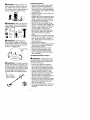
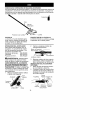
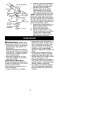
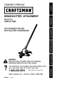
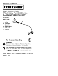
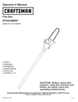
Instruction Manual
BRUSHCU'n'ER
ATTACHMENT
Model No.
358.792430
NOT DESIGNED
WITH ELECTRIC
FOR USE
POWERHEADS
• Safety
• Assembly
• Operation
• Maintenance
• Parts List
•
Espa_ol
DANGER:
Read and follow all Safety Rules and Operating
Instructions before first use of this product.
For answers to your questions about this product: Call 7
am-7 pm, Mon.-Sat., or 10 am-7 pm, Sun.
1-800-235-5878
Sears, Roebuck
530163558
8/26]02
and Co., Hoffman
<,oo,8
listed are Central Time)
Estates, IL 60179 U.S.A.
Warranty Statement
Safety Rules
Assembly
Operation
Maintenance
2
2
5
7
9
Service & Adjustments
Storage
Parts List
Spanish
Parts and Ordering
10
11
12
13
Back Cover
FULL ONE YEAR WARRANTY ON CRAFTSMAN® BRUSHCUTTER ATTACHMENT
For one year from the date of purchase, when this Craftsman Brushcutter Attachment is maintained and lubricated according to the operating and maintenance
instructions in this manual, Sears will repair, free of charge, any defect in materials or workmanship.
This warranty excludes expendable parts that become worn during normal use.
If this Craftsman Brushcutter Attachment is used for commercial purposes, this warranty applies for only 90 days from the date of purchase. If this Craftsman Brushcutter Attachment is used for rental purposes, this warranty applies for only 30 days from
the date of purchase.
This warranty applies only while this product is in use in the United States.
WARRANTY SERVICE IS AVAILABLE BY RETURNING THE CRAFTSMAN BRUSHCUTTER ATTACHMENT TO THE NEAREST SEARS STORE OR SERVICE CENTER IN THE
UNITED STATES.
This warranty gives you specific legal rights, and you may also have other rights
which vary from state to state,
Sears, Roebuck and Co., D/817 WA, Hoffman Estates, IL 60179
zl, ____.H_
4UkWARNING:
When using gardening appliances, basic safety precautions should always be followed to reduce the risk of fire and serious injury.
Read and follow all instructions. Failure to de so can result in serious injury.
_!_ DANGER:
This power tool can be
dangerous! This unit can cause serious injury including amputation or
blindness to the operator and others.
The warnings and safety instructions
in this manual must be followed to provide reasonable safety and efficiency
in using the unit. The operator is responsible for following the warnings
and instructions in this manual and on
the unit. Read the entire instruction
manual before assembling and using
the unit! Restrict the use of this unit to
persons who read, understand, and
follow the warnings and instructions in
this manual and on the unit. Never allow children to operate this unit.
INSTRUCTION
MANUAL
DANGER:
vices.
/
SAFETY INFORMATION
ON THE UNtT
Never use flailing de-
DANGER:
Blade can thrust vio*
lently away from material it does not
cut. Blade thrust can cause amputa*
tion of arms or legs. Keep people and
animals 50 feet (15 meters) away.
dlI_WARNING:
jects violently,
injured. Wear
ALWAYS
Blade
can throw ob-
You can be blinded or
eye and leg protection.
_
Eye
Protection
_t
• •
Leg
Guards
_
Boots
_IkWARNING:
Hazard zone for
thrown objects. Blade can throw objects violently. Others can be blinded
or injured. Keep people and animals
50 feet (15 meters) away.
OPERATOR SAFETY
• Dress properly. Always wear safety
glasses or similar eye protection
when operating, or performing maintenance on your unit (safety glasses
are available). Eye protection should
be marked Z87.
• Always wear face or dust mask if operation is dusty.
• Always wear heavy, long pants, long
sleeves, boots, and gloves. Wearing
safety leg guards is recommended.
• Always wear foot protection. Do not
go barefoot or wear sandals.
• Secure hair above shoulder length.
Secure or remove loose clothing and
jewelry or clothing with loosely hang*
ing ties, straps, tassels, etc. They
can be caught in moving parts.
• Being fully covered also helps protect you from debris and pieces of
toxic plants thrown by spinning
blade.
• Stay Alert. Do not operate unit when
you are tired, ill, upset or under influ*
ence of alcohol, drugs, or medication, Watch what you are doing; use
common sense.
• Wear hearing protection.
• Never start or run the engine inside a
closed room or building. Breathing
exhaust fumes can kill.
• Keep handles free of oil and fuel.
• Always use the handlebar and a
properly adjusted shoulder strap
when using brushcutter attachment
(see ASSEMBLY).
UNIT/MAINTENANCE
SAFETY
d Zone
Zl, _____.__
dI_IbWARNING: The blade continues
to spin after throttle is released or engine is turned off. The coasting blade
can throw objects or seriously cut you
if accidentally touched. Stop the blade
by contacting the left hand side of
coasting blade with material already
cut.
Stop coasting
blade by contact
with cut material.
_
_f
.,_
_I, WARNING:
Disconnect powerhead spark plug (or disconnect powerhead from power source) before performing maintenance.
• Look for and replace damaged or
loose parts before each use. Look
for and repair fuel leaks before use.
Keep unit in good working condition.
• Throw away blades that are bent,
warped, cracked, broken, or damaged in any other way. Replace trimmer head parts that are cracked,
chipped, broken, or damaged in any
other way before using the unit.
• Maintain the unit according to recommended procedures. Keep the blade
sharp. Never use flailing devices,
wire, rope, string, etc.
• Use only specified blade; make sure
it is properly installed and securely
fastened.
• Never
startengine
withclutchshroud
removed.
Theclutchcanflyoffand
cause
serious
injury.
• Besurebladestopsturning
when
engine
idles.
• Makecarburetor
adjustments
with
thelowerendsupported
toprevent
thebladefromcontacting
anyobject.
Holdtheunitbyhand;donotusethe
shoulder
strapforsupport.
• Keepothersawaywhenmaking
carburetor
adjustments.
• Useonlyrecommended
Craftsman
accessories
andreplacement
parts.
• Haveallmaintenance
andservice
notexplained
inthismanual
performedbya SearsService
Center.
FUEL SAFETY
• Mix and pour fuel outdoors.
• Keep away from sparks or flames.
• Use a container approved for fuel.
• Do not smoke or allow smoking near
fuel or the unit or while using the unit.
• Avoid spilling fuel or oil. Wipe up all
fuel spills before starting engine.
• Move at least 10 feet (3 meters) away
from fueling site before starting engine.
• Stop engine and allow it to cool before removing fuel cap.
• Remove fuel cap slowly.
CUTTING SAFETY
_!_WARNING:
Inspect the area to
be cut before each use. Remove objects (rocks, broken glass, nails, wire,
string, etc.) which can be thrown or become entangled in the blade.
• Keep others including children, animals, bystanders, and helpers at
least 50 feet (15 meters) away. Stop
the engine immediately if you are approached.
• Always keep engine on the righthand side of your body.
• Hold the unit firmly with both hands.
• Keep firm footing and balance. Do
not overreach,
• Keep blade below waist level.
• Do not raise powerhead engine above
your waist.
• Keep all parts of your body away
from blade and muffler.
• Cut from your right to your left.
• Use only in daylight or good artificial
light.
• Use only for jobs explained in this
manual.
TRANSPORTING AND STORAGE
• Stop the powerhead engine before
carrying unit.
• Keep muffler away from your body.
• Allow engine to cool and secure unit
before storing or transporting it in a
vehicle.
• Empty the fuel tank before storing or
transporting the unit. Use up fuel left
in the carburetor by starting the engine and letting it run until it stops.
• Store unit and fuel in an area where
fuel vapors cannot reach sparks or
open flames from water heaters,
electric motors or switches, furnaces,
etc.
• Store unit so the blade cannot accidentally cause injury.
• Store unit indoors, out of reach of
children.
SPECIAL NOTICE: Exposure to vibrations through prolonged use of gasoline powered hand tools could cause
blood vessel or nerve damage in the
fingers, hands, and joints of people
prone to circulation disorders or abnormal swellings. Prolonged use in cold
weather has been linked to blood vessel damage in otherwise healthy
people. If symptoms occur such as
numbness, pain, loss of strength,
change in skin color or texture, or loss
of feeling in the fingers, hands, or
joints, discontinue the use of this tool
and seek medical attention. An anti*
vibration system does not guarantee
the avoidance of these problems. Users who operate power tools on a continual and regular basis must monitor
closely their physical condition and the
condition of this tool.
SAVE THESE INSTRUCTIONS
CARTON CONTENTS
Check carton contents against the followinglist,
Model 358.792430
• Brushcutter Attachment
• Handlebar (with Clamp and Knob)
• Handlebar Clamp Base (with Spacer
Tabs)
• Shoulder Strap
• Upper Shoulder Strap Clamp
• Lower Shoulder Strap Clamp (with
Spacer Tabs)
• Handlebar Clamp Screws (4)
• Shoulder Strap Clamp Screws (2)
• Attachment Hanger
• Hex Wrench
Examine parts for damage. Do not use
damaged parts.
NOTE: If you need assistance or find
that parts are missing or damaged, call
1-800-235-5878.
Coupler
\
Upper
Tube
tl WARNING:
If received assembled,
repeat all steps to ensure your unit is
properly assembled and all fasteners
are secure.
• A hex wrench (provided) is required
for assembly.
INSTALLING BRUSHCUTTER ATTACHMENT
CAUTION: When removing or installing attachments, place the unit on a
flat surface for stability,
1. Loosen the coupler by turning the
knob counterclockwise.
Coupler
LOOSEN
Spacer T_
3.
4.
5.
Recess
Locking/
Lower
Release Attachment
Button
DANGER:
RISK OF CUT. To
avoid serious injury, the barrier portion of
the handlebar must be installed as
shown on the upper tube of the powerhead to provide a barrier between operator and the spinning blade. Attach
tube clamp above arrow on safety warning decal on the upper tube (powerhead
end of unit). Ensure handlebar is positioned on handlebar clamp between the
arrows on the handlebar decal.
NOTE: The tube clamp base has four
spacer tabs attached, These tabs are
provided to adapt this attachment for
use with powerheads that have a 1" diameter upper tube (the tube clamp will
not tighten down securely on the 1" diameter upper tube without using these
spacer tabs). The tabs must be broken
off completely before use and placed
over the screw holes on the clamp base.
These tabs are not needed for powerheads with a 7/8" upper tube.
HANDLEBAR CLAMP BASE
z't
2.
/_uide
_11_WARNING:
Make sure the locking/release button is locked in the primary hole and the knob is securely
tightened before operating the unit.
HANDLEBAR ASSEMBLY
ASSEMBLY
TIGHTEN
Primary Hole
_lb_
Knob
Spacer Tabs _
posi!ioned for use _
_
on 1 diameter
__p.,,'__
Remove the tube cap from the
brushcutter attachment (if present).
Position locking/release button of
attachment into guide recess of
coupler.
Push the attachment into the coupler until the locking/release button
snaps into the primary hole,
Before using the unit, tighten the
knob securely by turning clockwise.
upper tube
1.
2.
5
_U
Place the tube clamp over the upper tube above the arrow on the
safety decal.
Position the clamp base under the
upper tube and align the tube
clampandclampbasescrew
holes(usespacer
tabsbetween
tubeclampandclamp
baseif necessary
tosecure
clamp,i.e.for1"
diameter
uppertube).
LOWER SHOULD,_R STRAP
Spacer Tabs
Handlebar
POWERHEAD
END
4----- Spacer Tabs
positioned for use
on 1" diameter
Handlebar Clamp
between arrows on
handlebar decal
upper tube
Clam
Knob
1.
Screws
Clamp
2.
Arrow on
Safety Decal
ATTACHMENT
END
Insert four screws into the screw
holes.
4. Secure tube clamp by tightening
screws with the hex wrench.
5. Position the handlebar as shown,
ensuring the handlebar is positioned on the handlebar clamp between the two arrows on the handlebar decal.
6. Retighten handlebar byturning
clamp knob clockwise until handlebar is secure and stationary in
clamp (clamp knob cannot be
overtightened).
SHOULDER STRAP ASSEMBLY
Place the upper shoulder strap
clamp over the upper tube above
the handlebar.
Position the lower shoulder strap
clamp under the upper tube and
align the upper and lower clamp
screw holes (use spacer tabs between upper and lower clamps if
necessary to secure clamp, i.e. for
1" diameter upper tube).
3.
_WARNING:
Proper shoulder
strap and handlebar adjustments must
be made with the engine completely
stopped before using unit. The shoulder strap clamp must be installed as
shown above the handlebar on the upper tube (powerhead end of unit).
NOTE: The lower shoulder strap clamp
has two spacer tabs attached. These
tabs are provided to adapt this attach_
ment for use with powerheads that have
a 1" diameter upper tube (the shoulder
strap clamp will not tighten down se*
curely on the 1" diameter upper tube
without using these spacer tabs). The
tabs must be broken off completely be_
fore use and placed over the screw
holes on the lower shoulder strap clamp.
These tabs are not needed for power_
heads with a 7/8" upper tube.
Upper Shoulder
Clamp
POWERHEAD
END
Lower Shouldel
Strap Clamp
3.
END
ATTACHMENT
SCOWS
Insert two screws intothe screw
holes.
4. Secure shoulder strap clamp by
tightening screws with the hex
wrench,
5. Insert your right arm and head
through the shoulder strap and allow it to rest on your left shoulder,
Make sure the danger sign is on
your back and the hook is to the
right side of your waist.
NOTE: A one-half twist is built in the
shoulder strap to allow the strap to rest
flat on the shoulder,
6. Adjust the strap, allowing the hook
to be about 6 inches below the
waist,
7. Fasten the strap hook to the clamp
and lift the tool to the operating
position,
8. Try on shoulder strap and adjust
for fit and balance before starting
the engine or beginning a cutting
operation.
NOTE:It maybenecessary
torelocatetheshoulder
strapclamponthe
shaftforproperbalancing
ofunit.
HARNESS
ADJUSTMENT
FOR BALANCE
6 inches =
below
waist
30 inches
4 - 12
inches
above
.1_'_
round
KNOW YOUR BRUSHCUTTER ATTACHMENT
READTHiS INSTRUCTIONMANUALAND SAFETY RULES BEFORE OPERATING YOUR
BRUSHCUTTERATTACHMENT Compare the illustrations with your unit to familiarize
yourself with the location of various controls and adjustments. Save this manual for
future reference.
Hanger
BLADE
The BLADE is designed for cutting
grass, weeds, and brush upto 1/2 inch
in diameter.
OPERATING THE COUPLER
Your powerhead is equipped with a
coupler which enables optional attachments to be installed. The optional attachments are:
Edger ...............
358,792400
Cultivator ............
358.792410
Blower ..............
358.792420
BLADE SHIELD
The BLADE SHIELD provides protection
from the spinning blade.
_kWARNING:
Always disconnect
powerhead spark plug before removing or installing attachments.
REMOVING BRUSHCUTTER ATTACHMENT (OR OTHER OPTIONAL
ATTACHMENTS)
CAUTION: When removing or installing attachments, place the powerhead
and attachment on a flat surface for
stability.
1.
Loosen the coupler by turning
knob counterclockwise.
the
OPERATING
POSITION
ALWAYS WEAR:
Upper Tube
Coupler
Eye Protection
LOOSEN
Lower
Attachment
Heavy,
Long Pants _._
Boots _.
TIGHTEN
Knob
Press and hold the locking/release
button.
2.
NOTE: This brushcutter attachment is
not designed for use with electric pewerheads.
Locking/Release
Button
/
Lower Attachment
When operating unit with brushcutter
attachment, clip shoulder strap onto
upper shoulder strap clamp, stand as
shown and check for the following:
• Wear eye protection and heavy
clothing.
• Keep arms extended with right hand
holding the trigger handle of powerhead.
• Keep left arm extended with left hand
holding the handlebar.
• Keep unit below waist level.
• Shoulder strap pad should be centered on your left shoulder and danger sign centered on your back.
• Maintain full weight of tool on left
shoulder.
• Without bending over, keep the blade
near and parallel to the ground and
not crowded into material being cut.
OPERATING INSTRUCTIONS FOR
BRUSHCUTTER ATTACHMENT
• Blade Thrust is a reaction that only
occurs when using a bladed unit. This
reaction can cause serious injury such
as amputation. Carefully study this
section. It is important that you understand what causes blade thrust, hew
you can reduce the chance of its ec*
cutting, and how you can remain in
control of unit if blade thrust occurs.
• WHAT CAUSES BLADE THRUST Blade Thrust can occur when spinning blade contacts an object that it
does not cut. This contact causes
blade to stop for an instant and then
suddenly move or "thrust" away from
object that was hit. The "thrusting" reaction can be violent enough to cause
operator to be propelled in any direction and lose control of unit. The uncontrolled unit can cause serious injury
if blade contacts operator or others.
UpperTube
3.
While securely holding the upper
tube, pull the attachment straight
out of the coupler.
INSTALLING OPTIONAL ATTACHMENT
1. Remove the tube cap from the attachment (if present) and discard.
2. Position locking/release button of
attachment into guide recess of
upper tube coupler.
Coupler Primary Hole
uide Recess
Upper
Tube
Locking/
Release
Button
Attachment
3.
Push the attachment into the coupler until the locking/release button
snaps into the primary hole.
4. Before using the unit, tighten the
knob securely by turning clockwise.
INSTALLING ATTACHMENT
HANGER
An attachment hanger is provided for
storage when attachment is net in use.
To install hanger on attachment:
1. Remove the tube cap from the attachment (if present) and discard.
2. Press and hold the locking/release
button.
3. Push hanger onto the attachment
until the locking/release button
snaps into the hole.
8
• WHEN BLADE THRUST OCCURS
- Blade Thrust can occur without
warning if the blade snags, stalls, or
binds. This is more likely to occur in
areas where it is difficult to see the
material being cut. By using the unit
properly, the occurrence of blade
thrust will be reduced and the operator will be less likely to lose control.
i
• Cut only grass, weeds, and woody
brush up to 1/2 inch in diameter with
weed blade. Do not let blade contact
material it cannot cut such as stumps,
rocks, fences, metal, etc., or dusters
of hard, woody brush with a diameter
greater than 1/2 inch.
• Use a sharp blade. A dull blade is
more likely to snag and thrust.
• Cut only at full throttle. The blade will
have maximum cutting power and is
less likely to bind or stall.
• "Feed" the blade deliberately and not
too rapidly. The blade can thrust
away if it is fed too rapidly.
• Cut only from your right to your left.
Swinging unit in the same direction as
blade spin increases cutting action.
• Use the shoulder strap and keep a
firm grip on the unit with both hands.
A properly adjusted shoulder strap
will support the weight of the unit,
freeing your arms and hands to control and guide the cutting motion.
• Keep feet comfortably spread apart
and braced for a possible sudden,
rapid thrust of unit. Do not overreach.
Keep firm footing and balance.
• Keep blade below waist level. It will
be easier to maintain control of unit.
• Do not raise the engine above your
waist as the blade can come dangerously close to your body.
• Do not swing the unit with such force
that you are in danger of losing your
balance.
Bring the powerhead engine to cutting
speed before entering the material to
be cut.
If the blade does not turn when you
squeeze the throttle trigger of the powerhead, make sure the attachment is
fully inserted into the coupler,
Always release the throttle trigger and
allow powerhead engine to return to
idle speed when not cutting, The blade
should not turn while the engine is running at idle, If the blade turns at idle,
do not use your unit. Refer to the CARBURETOR ADJUSTMENT section of the
powerhead manual or contact your
Sears Service Center,
• Maintain good firm footing while using the unit. Do this by planting feet
firmly in a comfortable apart position.
• Cut while swinging the upper part of
your body from right to left,
• As you move forward to the next
area to cut, be sure to maintain your
balance, and footing.
RECOMMENDED CUTTING POSITION
,fiZ
10 o'clock _
Cut using the 8 o'clock I |'.,_ _))
to 10 o'clock position of -y "[1
the blade
8 o'clock_'_ _'_
a_IbWARNING:
The operator or others must not try to clear away cut material with the engine running or the
blade turning to avoid serious injury.
Stop engine and blade before removing materials wrapped around blade or
tube.
MAINTENANCE SCHEDULE
_IkWARNING:
Always stop unit and disconnect
performing maintenance.
CARE AND MAINTENANCE
WHEN TO PERFORM
TASK
Before each use
Check for loose fasteners and parts
Check for damaged or worn parts
Inspect and clean unit and decals
Check or replace blade
GEN ERAL RECOMMEN DATIONS
The warranty on this attachment does
not cover items that have been subjected to operator abuse or negligence. To receive full value from the
warranty, the operator must maintain
the brushcutter attachment as instructed in this manual.
CHECK FOR DAMAGED OR
WORN PARTS
Contact Sears Service Center for replacement of damaged or worn parts.
• Blade Shield - Discontinue use of
brushcutter attachment if shield is
damaged.
• CHECK FOR LOOSE
FASTENERS AND PARTS
• Blade nut
• Fasteners
INSPECT AND CLEAN UNIT
AND DECALS
• After each use, inspect complete unit
for loose or damaged parts. Clean
the unit and decals using a damp
cloth with a mild detergent.
BLADE REPLACEMENT
Before each use
After each use
Every 5 hours of operation
• Wipe off unit with a clean dry cloth.
BLADE MAINTENANCE
_II, WARNING:
The blade will continue to spin after the engine stops or after the throttle trigger has been released. To avoid serious injury, make
sure the blade has stopped coasting
and disconnect the spark plug before
performing work on the blade.
_IkwARNING:
Always replace a
blade that is bent, warped, cracked,
broken, or damaged in any other way.
Never attempt to straighten and reuse
a damaged blade. Use only specified
replacement blade. Wear protective
gloves when handling or performing
maintenance on the blade to help
avoid injury.
• Check blade for flatness periodically.
Lay the blade on a flat surface to inspect for flatness. Throw away a
blade that is net flat.
2.
_JkWARNING:
The blade will continue to spin after the engine stops or after the throttle trigger has been released. To avoid serious injury, make
sure the blade has stopped coasting
and disconnect the spark plug before
performing work on the blade.
_IkWARNING:
Wear protective
gloves when handling or performing
maintenance on the blade to avoid
injury. The blade is sharp and can cut
you even when it is not moving.
1. To remove the blade, align hole in
the dust cup with the hole in the
side of the gearbox by rotating the
blade.
spark plug wire before
Insert a small screwdriver into
aligned holes. This will keep the
shaft from turning while loosening
the blade nut.
Screwdriver
3.
4.
10
While holding the screwdriver in
position, remove blade nut by turning clockwise as you are facing the
nut,
Remove both washers and the
blade from the blade shaft. Leave
the dust cup on the gearbox.
5.
Install new blade and retaining
washer onto the threaded shaft extending from the gearbox (blade
must be between the dust cup and
the retaining washer), Make sure
the raised part of the retaining
washer is facing the gearbox, and
the raised area fits into the hole in
the center of the blade.
Gearbox
Shield
Dust Cu
Threaded
Shaft
6.
Place the cupped washer onto the
shaft, Make sure the cupped side
of the washer is toward the blade.
7. Install blade nut by threading onto
the shaft counterclockwise as you
are facing the nut.
NOTE: Make sure all parts are in place
as illustrated, and the blade is sandwiched between the dust cup and the
retaining washer. There should be no
space between the blade and the dust
cup or the retaining washer.
8. Tighten blade nut firmly with a
wrench while holding screwdriver
in position.
9. Remove the screwdriver,
10. Turn blade by hand, If the blade
binds against the shield, or appears to be uneven, the blade is
not centered, and you must reinstall.
Blade
Retaining
Washer
Cupped_._,.,--_-->
Washer
_-,_-_Nut
_IbWARNING:
Perform the following
steps after each use:
• Allow attachment and gearbox to
cool before storing or transporting,
• Store attachment with blade shield in
place. Position attachment so that
any sharp object cannot accidentally
cause injury.
• Store the attachment in a dry, well
ventilated area out of the reach of
children.
SEASONAL STORAGE
Prepare attachment for storage at end
of season or if it will not be used for 30
days or more.
If your brushcutter attachment is to be
stored for a period of time:
• Clean the entire attachment,
• Inspect the blade shield area and
clean any dirt, grass, leaves, or debris that has collected. Inspect the
blade and blade shield; replace a
blade that is bent, warped, cracked,
broken or damaged in any other way.
• Lightly oil external metal surfaces,
• Apply a coating of oil to the entire
surface of the blade; wrap it in heavy
paper or cloth,
• Check entire attachment for loose
screws or nuts. Replace any damaged, worn or broken parts.
• At the beginning of the next season,
use only fresh fuel having the proper
gasoline to oil ratio.
11
Declaraci6n
deGarantia
Reglas
deSeguridad
Montaje
Uso
Mantenimiento
13
13
16
18
21
Servicio
yAjustes
22
Almacenaje
23
ListadePiezas
12
Repuesto
yEncargos Contratapa
GARANTIA COMPLETO DE UN AI_IO PAPA LA CORTADORA
ACCESORIO CRAFTSMAN ®
DE MALEZAS
Durante un aho completo, a partir de la fecha de compra, siempre que se haga el
mantenimiento, la lubricaci6n y los ajustes a esta Cortadora de Malezas Accesorio Craftsman segL_nlas instrucciones de uso y mantenimiento en el manual,
Sears reparar_ cualquier defecto de materiales o de mano de obra gratuitamente.
Esta garantia excluye las partes que se gastan durante el uso normal.
Si se usa esta Cortadora de Malezas Accesorio Craftsman con fines comerciales,
esta garantia tendr_ validez por s61a 90 dias a partir de la fecha de compra. Si se
usa esta Cortadora de Malezas Accesorio Craftsman con fines de alquiler, esta
garantia tendr_ validez s61amente por 30 dias a partir de la fecha de compra,
Esta garantia tendr_ validez t]nicamente mientras se use este producto dentro de
los Estados Unidos.
SE OBTENDRA SERVIClO BAJO GARANTIA DEVOLVIENDO LA CORTADORA DE MALEZAS ACCESORiO CRAFTSMAN AL TIENDA CE SEARS O CENTRO DE SERVICIO
SEARS MAS CERCANO EN LOS ESTADOS UNIDOS.
Esta garantia confiere derechos legales especificos al propietario, que tal vez
tenga asimismo otros derechos que varian entre estados.
Sears, Roebuck and Co., D/817 WA Hoffman Estates, IL 60179
LI_ADVERTENCIA:
AI usar cualquier herramienta de fuerza de jardineria,
deber&n observarse precauciones basicas de seguirdad en todo momento
para reducir el riesgo de incendio y
graves heridas. Lea y cumpla con todas
Ins instrucciones. Su incumplimiento
puede ocasionar lesiones graves.
PELIGRO:
i Esta herramienta motorizada puede ser peligrosa! Puede
ocasionar lesiones graves, incluso la
amputaci6n o la ceguera, tanto al operador como a otras personas. Las advertencias e instrucciones de seguridad
contenidas en este manual deben cumplirse en todo momento para garantizar
un nivel de seguridad y efectividad razonable durante la utilizaci6n del aparato. El operador es responsable del
cumplimiento de las advertencias e
instrucciones indicadas en este manual
yen el aparato. Antes de ensamblar y
utilizar el aparato, lea integramente el
manual de instrucciones, Limite el uso
de este aparato a personas que previamente hayan leido y comprendido, y
posteriormente cumplan, las advertencias e instrucciones indicadas en este
manual yen el aparato. Nunca permita
que este aparato sea utilizado por nihos,
MANUAL DE
JNSTRUCCIONES
PELIGRO:
desgranadores.
13
/
INFORMACION
DE
SEGURIDAD DEL
APARATO
Nunca usedispositivos
_1_PELIGRO:Lacuchilla
puede
rebotarviolentamente
enmateriales
queno
puede
cortar.
Losrebotes
dela cuchilla
pueden
causar
]aamputaci6n
debrazos
opiernas.
Mantenga
apersonas
yanimaleslejosdelaherramienta
(15metros).
iIFa
rauad
neten
girreaIi_UeChimente, p6ngala en
__
""
SEGURIDAD DEL OPERADOR
• Vistase apropiadamente.
Siempre
use anteojos de seguridad o similar
protecci6n para los ojos cuando use
o de mantenimiento a este aparato
_I_ADVERTENClA:
Lacuchilla
(anteojos de seguridad estAn dispoLa protecci6n para los ojos
puede
despedir
objetos
violentamente. nibles).
debe ser marcada con Z87.
Estepuedeocasionarle
ceguera
o le• Siempre utilize mascarilla para la
sienes.
Pret6jase los ojes y las piercara o mascarilla a prueba de polvo
nas.
si se va a trabajar en condiciones
UTILICE SIEM
donde hay polvo.
Protecci6n
• Siempre utilize pantalones pesados
ocular
y largos, mangas largas, botas y
guantes. Se recomienda el use de
pantorrilleras de seguridad.
• Siempre utilize protecci6n para los
pies. No trabaje descalzo ni en
sandalias. Evite la cuchilla girante.
• Mantenga el cabello per encima de
_ILADVERTENClA:
Zona de pelf
los hombres, at&ndolo para tal efecto
gro de objetos despedidos. La cuchilla
si es necesario. No use ropa suelta
puede despedir ebjetes vielentamente.
ni ropa con corbatas, tiras, borlas,
Este puede ocasionar ceguera e lesieetc. que cuelgan libremente. Pueden
nes a otres. Mantenga a personas y
enredarse en las piezas en movianimales lejes de la herramienta 15
miento.
metros (50 pies).
• Si est9 completament tapado, estara
m_s protegido de los escombros y
pedazos de plantas t6xicos arrojae peligro
dos per la cuchilla girante.
• Mant6ngase alert& No haga uso del
aparato estando cansado, enfermo,
trastornado o bajo la influencia del
alcohol, de drogas o de remedios.
_d
Zona
Vigile bien Io que est& haciendo; use
del sentido comL_n.
• Use protecci6n de oidos.
• Nunca ponga el aparato en marcha
a_IbADVERTENClA:
La cuchilla sini Io deje en marcha dentro de un
gue girando incluso despues de seltar
recinto cerrado. Respirar los vapores
el acelerader e de apagar el motor. Indel combustible Io puede matar.
cluso cuande est9 girando libremente,
• Mantenga las manijas libres de
la cuchilla puede despedir objetos o
aceite y de combustible.
causar cortes profundes si se toca ac• Utilice siempre el mango y una
cidentalmente. Detenga la cuchilla pecorrea para hombre correctamente
niendo en contacte el lade izquierdo
ajustada al usar la cortadera de
de la misma con material ya certado.
ma]ezas acceserio (yea MONTAJE).
14
MANTENIMIENTO
DEL APARATO
Y SEGURIDAD
z*=
ADVERTENCIA:
Desconecte la
bujia (o desconecte aparato de la corriente el6ctrica) antes de hacer cualquier mantenimiento.
• Antes de cada uso, busque las piezas
dafiadas o sueltas y sustitOyalas. Antes de cada uso, busque posibles fugas de combustible y, en su caso, rep&relas, Mantenga el aparato en buen
estado de funcionamiento.
• Deseche la cuchillas dobladas, dentadas, partidas, rotas o deterioradas
de a]gt3n modo. Antes de utilizar la
unidad, sustituya las piezas del cabezal podador que esten partidas,
rotas o deterioradas de algQn modo.
• Realice el mantenimiento del aparato
siguiendo los procedimientos recomendados. Mantenga la cuchilla afilada. Nunca utilice dispositivos desgranadores, cable, cuerda, alambre, etc.
• Utilice exclusivamente la cuchilla especificado y aseg_rese de que est6
correctamente instalado y firmemente sujeto,
• Nunca ponga en marcha el motor
con el cubierta del embrague desmontado, El embrague podria desprenderse y causar graves lesiones.
• AsegQrese de que el cuchilla se detiene al pasar el motor al ralenti.
• Realice los ajustes del carburador
con la parte inferior apoyada en alto
para impedir que la cuchilla entren
en contacto con algt]n objeto. Suiete
el aparato con las manos, sin utihzar
la correa al hombro.
• Cuando realice ajustes en el carburador, mantenga alejadas del lugar a
otras personas.
• Utilice exclusivamente los accesorios y recambios recomendados por
Craftsman.
• Confie todas las tareas de mantenimiento y reparaci6n no explicadas
en este manual a su Centro de
Servicio de Sears.
SEGURIDAD CON EL COMBUSTIBLE
• Mezcle y vierta el combustible en
exteriores.
• Mantenga el combustible alejado de
chispas y llamas.
• Utilice recipientes homologados para
el uso de combustibles.
• Impida que se fume cerca del combustible o del aparato, tanto si 6ste
se encuentra parado o se est& utilizando,
• Antes de poner en marcha el motor,
limpie todo posible resto de combustible derramado,
• Antes de poner en marcha el motor,
al6jese como minimo 3 metros del lugar de repostaje,
• Antes de quitar el tap6n de combustible, detenga el motor y dejelo enfriar.
• Remueva la tapa del tanque de combustible lentamente.
SEGURIBAD AL CORTAR
G_,ADVERTENClA:
Antes de cada
uso, inspeccione la zona de trabajo,
Retire todos los objetos (rocas, cristales rotos, clavos, cables, hilos, etc,)
que puedan ser despedidos o quedar
enredados en la cuchilla,
• Mantenga alejados del lugar de trabajo (15 metros) a otras personas,
ya sean nifios, acompaSantes o ayudantes, y a animales. Detenga el
motor tan pronto como alguien se le
aproxime.
• Mantenga siempre el motor junto al
lado derecho de su cuerpo.
• Sujete firmemente la unidad con ambas manos.
• Pise con seguridad y mantenga el
equilibria en todo momento. No estire el cuerpo en exceso.
• Mantenga la cuchilla por debajo de
la cintura.
• No levante el cabeza de motor por encima de su cintura.
• Mantenga todas las partes de su
cuerpo alejadas de la cuchilla y del
silenciador.
• Corte siempre de derecha a izquierda.
• Use el aparato t_nicamente de dia o
en luz artifcial fuerte.
• Utilice el aparato solamente para las
tareas explicadas en este manual.
TRANSPORTE Y ALMACENAMIENTO
• Antes de proceder a su transporte,
detenga el cabeza de motor.
• Mantenga el silenciador alejado del
cuerpo.
• Antes de almacenar o transportar el
aparato en un vehiculo, deje enfriar
el motor y sujete bien el aparato.
• Antes de guardar o transportar el
aparato, vacie el dep6sito de combustible. Arranque el motor y dejelo
en marcha hasta que se detenga
con el fin de agotar el combustible
que pueda quedar en el carburador,
• Guarde el aparato y el combustible
en un lugar donde los vapores emanados del combustible no puedan
entrar en contacto con chispas ni llamas procedentes de calentadores
15
deagua,motores
o interruptores
el6ctricos,
hornos,
etc.
• Guarde
el aparato de mode que la
cuchilla no puedan ecasienar lesiones accidentalmente.
• Guarde el aparate dentre, fuera del
alcance de los niSos.
NOTA ESPECIAL: El estar expueste
alas vibraciones a trav6s del use prolengade de herramientas de fuerza a
gasolina puede cuasar daSes a los vases sanguineos o a los nervios de los
dedos, las manes y las ceyunturas en
aquellas personas que tienen propem
sidad a los trastemos de la circulaci6n
o a las hinchazenes anermales. El use
prelongado en tiempe frio ha side aseciade con daSes a los vases sna-
CONTENIDO DE LA CAJA
Use la siguiente lista para verificar que
todas la piezas hayan side incluide:
Model 358.792430
• Cortadera de Malezas Acceserie
• Mango (con Abrazadara y Perilla)
• Base de Abrazadera (con Tabulaciones
del Espaciador)
• Correa al Hombre
• Abrazadera Superior del Correa de
Hombre
• Abrazadera
Inferior del Cerrea de
Hombre (con Tabulaciones del Espaciador)
• Tornillos de Abrazadera del Mango (4)
• Tornilles de Abrazadera del Correa de
Hombre (2)
• Suspenser del Accesorie
• Llave Hexagonal
Aseg_rese de que ninguna pieza est6
da5ada. No utilice piezas daSadas.
NOTA: Si necesita ayuda e detecta que
alguna pieza falta e est9 daSada, Ilame
al 1-800-235-5878.
MONTAJE
A'I,
_
d_ILADVERTENCIA:
Si recibe el
aparato ya armado, repita tedos los pasos para asegurarse de que el aparate
est6 cerrectamente ensamblade y todas
las sujecienes firmes.
• Un Ilave hexagenale (incluidas) se
requiere para el montaje.
INSTALAClON DE LA ACCESORIO
DEL CORTADORA DE MALEZAS
PRECAUClON: AI instalar las accesorio, penga el aparato en una superficie plana para estabilidad.
guineos de personas que per otra
parte se encuentran en perfecto estado de salud. Si ocurren sintomas tales
come el entumecimiento, el dolor, la
falta de fuerza, los cambios en el color
o la textura de la piel o falta de sentido
en los dedos, las manes o las coyunturas, deje de usar esta maquina inmediatamente y procure atenci6n
m6dica, Los sistemas de anti-vibraci6n no garantizan que se eviten tales
problemes. Los usuarios que hacen
use continue y prolongando de las
herramientas de fuerza deben fiscalizar atentamente su estado fisico y el
estado del aparato.
GUARDE ESTAS INSTRUCCIONES
1.
Afloje el acoplador dando vuelta a
la perilla a la izquierda.
Acoplador
AFLOJE
Perilla
2.
3.
4.
5.
Retire la tapa de tube del accesorio del cortadora de malezas (si
presente).
oloque el bot6n de conexi6n/desconexi6n del accesorio en el agujere de la guia del acoplador.
Empuje el accesorio en el acoplador hasta que el bot6n de conexi6n/desconexi6n se encaje en el
primer agujero,
Antes de usar el aparato, apriete
la perilla flrmemente dando vuelta
a la derecha.
Acoptador
\
Tube
Superior
16
Pdmer
Agujero Agujero de
/
la Guia
Bot6n de Accesorio
Conexi6n/ Inferior
Descorlexi6n
Ie!t.ADVERTENClA:
Antesdeoperarestaaparate,
aseg_rese
dequeel
Coloque la base de la abrazadera
debajo del tubo superior y alinee
los huecos del tornillo de la abrazadera con el tubo y la base de la
abrazadera (use las tabulaciones
del espaciador entre la abrazadera
del tubo y la base de la abrazadera
en caso de nec_sidad para asegurar la abrazadera, es decir para 1
pulgada de diametro del tubo superior).
2.
bot6n de cenexi6n/desconexi6n
est6
asegurado en el primer agujero y la
perilla est6 bien ajustada, Todos los
accesorios han side disefiados para
ser utilizades en el primer agujere.
INSTALLATION DEL MANGO
,I_kPELIGRO:
RIESGO DE CORTADURA, Para evitar graves heridas, la
parte del mango en forma de barrera
debe ser instalada en el tube superior
de la cabeza del meter/tubo superior
con el fin de mantener la distancia
entre el operador y la cuchilla durante
el giro de 6sta. Instale la abrazadera
del tubo sebre la flecha de la etiqueta
de seguridad del tube superior (extremo a la cabeza del motor de su aparato). Asegure que el mango este en
posici6n con la abrazadera del mango
entre las flechas de la etiqueta del
mango.
AVISO: La base de la abrazadera del
tubo tiene cuatro (4) tabulacienes del
espaciador incluidas, Estas tabulaclones se proporcionan para adaptar
esta accesorio para el use con las cabezas de motor/tubo superior que tienen 1 pulgada del tubo superior de
diametro (la abrazadera del tubo no
apretar_ abajo con seguridad en el
tubo superior de 1 pulgada de di_metro sin usar estas tabulaciones del espaciador). Estas tabulaciones se deben remover antes del uso y ponerlos
sobre los huecos del tornillo en la
base de la abrazadera. Estas tabulaclones no son necesarias para las cabezas de motor/tubo con un 718de
pulgada en el tubo superior.
BASE DE ABRAZADERA
Tabulacione
s_
_%_P_
del Espaciador
_
Mango
Abrazadera del
Mango entre las
flechas de la eti¢
del mango
Base de
Abrazadera
Perilla
de la
Abrazadera
del tubo
Tornillos
Flecha en la
Etiqueta de Seguridad
EXTREMO CON
EL ACCESORIO
3.
Inserte cuatro tornillos en los huecos del tornillo.
4. Asegure la abrazadera del tubo
apretando los tornillos con la Ilave
hexagonal.
5. Coloque el mango como se lea
mostrado, asegurado el mango se
coloca en la abrazadera del mango entre las dos flechas en la etiqueta del mango.
6. Vuelva a apretar el mango dando
vuelta a la perilla de la abrazadera
hacia la derecha hasta que el
mango es seguro e inm6vil en la
abrazadera (la perilla de la abrazadera no se puede apretar demasiado).
MONTAJE DE LA CORREA PARA
HOMBRO
ADVERTENCIA:
del Espaciador
_
colocadas para el
uso en el I pulgaTabulaciones
da
de diametro del ,_
tubo superior
1.
•
Coloque la abrazadera del tube en
la parte superior sobre la flecha en
la etiqueta de seguridad.
EXTREMO CON
EL CABEZA DE
MOTOR
Antes de hacer
algun ajuste de la correa o el mango, es
imprescindible que el motor este
completamente detenido. El abrazadera
del correa de hombre debe ser instalado
sobre el mango en el tube superior
(extremo con el cabeza del motor).
AVlSO: La abrazadera inferior del
correa para hombro tiene dos (2) tabulaciones del espaciador incluidas. Es17
tastabulaciones
seproporcionan
para
adaptar
estaaccesorio
paraelusocon
lascabezas
demotor/tubo
superior
quetienen1pulgada
deltubosuperior
dedi&metro
(laabrazadera
delcorrea
parahombro
noapretar9
abajocon
seguridad
eneltubesuperior
de1pup
gadadediAmetro
sinusarestastabulaciones
delespaciador).
Estas
tabu*
laciones
sedebenremover
antesdel
useyponerlos
sobreloshuecos
del
tornilloenlaabrazadera
inferior
dela
correaparaelhombre.Estas
tabulaclonesnosonnecesarias
paralasca_
bezas
demotor/tube
conun7/8de
pulgada
eneltubosuperior.
ABRAZADERA
INFERIOR
DEL
CORREA
PARAHOMBRO
_
_,_1)_
_._m
1.
2.
Asegure la abrazadera de la correa para el hombre apretando los
tornillos con la Ilave hexagonal.
5. Introduzca el brazo derecho y la ca*
beza por el arco de la correa y apo_
ye esta en el hombro izquierdo.
Asegt]rese de que el signo de peli_
gro se encuentre en su espalda y
de que el enganche se encuentre
en el ]ado derecho de su cintura.
AVlSO: La correa puede girarse media
vuelta para garantizar que quede apoyada en toda su anchura sobre el
hombro.
6. Ajuste la correa para permitir que
el enganche quede a unos 15 cm
por debajo de la cintura.
7. Fije el enganche de la correa a la
abrazadera y levante la herramiem
ta hasta la posici6n de trabajo.
8. Antes de poner en marcha el motor
o iniciar cualquier tarea de corte,
p6ngase la correa en el hombro y
ajt]stela a su medida de modo que
le permita mantener el equilibrio.
Puede ser necesario mover la
TabulacionesAVlSO:
de la correa para el hombro
delEspaciador abrazadera
en el eje para un equilibrio apropiado
colocadas para el
del aparato.
uso en el 1 pulgada de diametro del
tubo superior
AJUSTE DEL
Coloque la abrazadera superior de
la correa para hombre en la parte
superior sobre la mango.
Coloque la abrazadera inferior de la
correa para hombro debajo del tubo
superior y alinee los huecos del tor*
nillo de la abrazadera superior y la
abrazadera inferior (use las tabulaciones del espaciador entre la abrazadera superior y abrazadera inferior en caso de necesidad para
asegurar la abrazadera, es decir
para tubos de 1 pulgada de diametro del tubo superior).
EXTREMO CON
EL CABEZA DE
MOTOR
4.
CORREA AL HOMBRO
PARAEL BALANCE
15cm
(6 pulgadas) debajo de la
cintura
10 - 30 cm
(4 - 12 pulgadas) det
Abrazadera Superior
de la Correa para
Hombro
76 cm
(30 pulgadas)
I
EXTREMO
CON
EL ACCESORIO
Abrazadera
Inferior de la
Correa para Hombro
3.
Inserte dos tornillos en los huecos
para tornillo.
18
CONOZCA
SU CORTADORA
DE MALEZAS ACCESORIO
LEA ESTE MANUAL DE INSTRUCCIONES Y LAS REGLAS DE SEGURIDAD ANTES DE
COMENZAR A USAR ESTE CORTADORA DE MALEZAS ACCESORIO. Compare las
ilustraciones con su aparato para familiarizarse con la ubicaci6n de los diversos
controles y ajustes. Guarde este manual para uso futuro.
Suspensor
Cuchilla
CUCHILLA
La CUCHILLA ha sido diseSada para
cortar hierba, plantas de pequefio tama5o y brozas con tallos de madera
de hasta 13 mm de di&metro.
PROTECTOR DE LA CUCHILLA
El PROTECTORDE LA CUCHILLA protege
al operador de la cuchilla girante.
OPERACION DEL ACOPLADOR
Este modelo est& equipado con un
acoplador, el cual permite la instalaci6n de accesorios opcionales. Los
accesorios opcionales son:
Cortadora de Bordes..
358.792400
Cultivador ...........
358.792410
Propulsor de Aire .....
358.792420
2.
ADVERTENCIA:
Siempre desconecte la bujia de la cabeza de motor
antes de retirar o instalar los accesorios.
COMO REMOVER EL ACCESORIO
DEL CORTADORA DE MALEZAS (U
OTROS ACCESORIOS OPClONAL)
PRECAUClON: AI retirar o instalar las
accesorios, ponga el cabeza de motor
y el accesorio en una superficie plana
para estabilidad.
1. Afioje el acoplador dando vuelta a
la perilla a la izquierda.
Tubo
Acoplador
Oprima y sostenga el bot6n de
conexi6n/desconexi6n.
Bot6n de Conexi6n/
Desconexion
Tubo Superior
Accesorio
Inferior
3.
Mientras sostiene el tubo superior
con firmeza, retire el accesorio in*
ferior del acoplador en forma recta.
INSTALACION DEL ACCESORIOS
OPCIONAL
1. Retire la tapa de tubo del acceso_
rio (si presente) y deseche.
2. Coloque el bot6n de conexi6n/desconexi6n del accesorio inferior en
el agujero de la guia del acoplador
de la tubo superior,
Primer
Acoptador
Agujero Agujero de
AFLOJE
\
/
la Guia
Accesono
Inferior
Tubo
Superior
Perilla
19
Bot6n de Accesorio
Conexi6n/ Inferior
Desconexion
3. Empuje
elaccesorio
inferiorenel
acoplador
hastaqueelboronde
conexi6n/desconexi6n
seencaje
enelprimeragujero.
4. Antesdeusarelaparato,
apriete
laperillafirmemente
dandovuelta
a laderecha.
INSTACALION DEL SUSPENSOR
Una suspensor de la accesorio se proporciona para el almacenaje cuando la
accesorio no se est9 utilizando.
Para instalar la suspensi6n en la accesorio:
1. Retire la tapa de tube del accesorio (si presente) y deseche.
2. Presione y sostenga el boron de
conexi6n/desconexi6n.
3. Empuje la suspensor sobre la accesorio hasta que el bot6n de conexi6n/desconexton se encaja en el
hueco.
POSIClON DE USO
SIEMPRE
USE:
Protecci6n
para los
Ojos
Pantalones
Pesados
y Largos
AVlSO: Esta cortadora de malezas
accesorio no se diseria para el use
con los cabezas del motor el6ctricos.
Cuando aparato de funcionamiento
con el cortadora de malezas accesorio, enganche la correa para hombro
en el abrazadera de la correa para el
hombro, par6se como se vea en la figura y verifique Io siguiente:
• Usando anteojos de seguridad y
ropa gruesa como protecci6n.
• Mantenga brazos extendido con la
mano derecha sostiene el mango del
gatillo acelerador del cabeza de motor.
• Mantenga el brazo izquierdo extendido con la mano izquierda sostenga el
mango.
• Mantenga el aparato por debajo de
la cintura.
• Mantenga almohadilla de la correa al
hombro centrada en el hombro
izquierdo y serial de peligro centrada
en su espalda.
• Mantenga todo el peso de la herramienta en el hombro izquierdo.
• Sin tener que inclinarse, mantenga
la cuchilla debe permanecer paralelo
al suelo y entrar f_cilmente en corn
tacto con el material a cortar.
INSTRUCCIONES DE MANEJO CON
CORTADORA DE MALEZAS
ACCESORIO
• El Rebote de la Cuchilla es una
reacci6n que s61o se produce cuando el aparato est9 equipado con una
cuchilla. Esta reacci6n puede causar graves lesiones, como la amputaci6n. Estudie detenidamente esta
secci6n. Es importante que el usua_
rio comprenda por qu6 se producen
los rebotes, c6mo reducir las probabilidades de que ocurran y c6mo
mantener el control del aparato
cuando se producen,
• CAUSAS DEL REBOTE DE LA
CUCHILLA - El Rebote de la
Cuchilla puede producirse cuando
la cuchilla en rotaci6n entra en contacto con un objeto que no puede
cortar. Este contacto detiene la
cuchilla durante un instante y la aleja sObitamente del objeto tocado. La
reacci6n de "rebote" puede ser Io suficientemente violenta para empujar
al operador en cualquier direcci6n y
hacer que pierda el control del aparate. Una vez fuera de control, el
aparato puede causar lesiones graves si la cuchilla entra en contacto
con.el operador u otras personas.
• CUANDO SE PRODUCE UN REBOTE DE CUCHILLA - El Rebete de
la Cuchilla puede ocurrir sin previo
aviso siesta se cala, engancha o
traba. La probabilidad de que esto
ocurra aumenta en las zonas donde
resulta dificil ver el material a cortar.
Utilizando el aparato adecuadamente se reduce el nt]mero de rebotes
de cuchilla y la probabilidad de que
el operador pierda el control.
• Con la cuchilla para hierbas s61o
puede cortarse hierba, plantas de
pequerio tamario y brozas con tallos
de madera de hasta 13 mm de di_metro. No permita que la cuchilla
entre en contacto con material que
no puede cortar, como tocones, piedras, vallas, metales, etc. o grupos
de tallos de broza con digmetros superiores a 13 mm.
20
• Mantenga
lacuchilla
bienafilada,
Si la cuchilla no gira al apretar el gatillo
Unacuchilla
romapuede
enganchar-del acelerador, asegQrese de que la
sey rebotar
conm_sfacilidad.
barra este completamente insertada
• Corte
solamente
aplenapotencia, en el motor.
Asi,lacuchilla
dispondr9
delamg_xi- Siempre que no est6 cortando, suelte
mapotencia
decorteytendra
menos el gatillo del acelerador y deje que el
posibilidades
decalarse
otrabarse, motor regrese a la velocidad de ra• "Alimente"
lacuchilla
concuidado
yno lenti. La cuchilla no debe girar mien*
demasiado
r_pidamente.
Lacuchilla tras el motor se encuentre al ralenti, Si
puede
rebotar
siseleobliga
acortar la cuchilla sigue girando con el motor
demasiado
material
almismo
tiempo, al ralenti, no utilice el aparato, Con*
• Cortesolamente
dederecha
a izsuite la secci6n de ajustes del carbuquierda.
Laacci6n de corte aumenta
rador o p6ngase en contacto con el
si se desplaza el aparato en la misma direcci6n que gira la cuchilla.
• Utilice la correa al hombro y mantenga bien sujeto el aparato con ambas
manos, Una correa al hombro ajustada correctamente absorber_ el peso del aparato, dejando libres sus
brazos y manes para controlar y
guiar el movimiento de corte,
• Mantenga los pies separados c6modamente y bien apoyados en previsi6n de que el aparato rebote repentinamente. No estire el cuerpo en
exceso, Mant6ngase firmemente en
postura erguida y equilibrada,
• Mantenga la cuchilla per debajo de
la cintura; asi le resultar9 mas f_cil
mantener el control del aparato,
• No levante el motor por encima de su
cintura, ya que la cuchilla podria acercarse peligrosamente a su cuerpo,
• No balancee el aparato con tal fuerza que pueda perder el equilibrio,
Antes de penetrar en el material a cortar, acelere el motor hasta la velocidad
de corte.
CRONOGRAMA
Centro de Servicio Sears.
• Mant6ngase firmemente en pie y
pise con seguridad siempre que utilice el aparato, Para ello, mantenga
los pies c6modamente separados,
• Corte mientras balancea la parte
superior de su cuerpo de derecha a
izquierda,
• Mientras avanza a la siguiente zona
de corte, cerci6rese de mantener el
equilibrio y de pisar firme.
POSICION
10 en
RECOMENDADA
PARA CORTAR
Corte utilizando la
seccion de la cuchilla
correspondiente
a la franja horaria
entre ias 8 y las 10.
punto
A
ADVERTENCIA:
Para evitar
graves lesiones, ni el operador ni otras
personas deben intentar retirar el material de corte mientras el motor est6
en marcha o la cuchilla se encuentre
girando, Antes de retirar materiales enrollados alrededor de la cuchilla o de
la barra, detenga el motor y la cuchilla,
DE MANTENIMIENTO
ADVERTENCIA:
Siempre apague el aparato y desconecte
antes de hacer cualquier mantenimiento.
TAREA DE CUIDADO Y MANTENIMIENTO
Verificar que no haya piezas ni fijadores sueltos
Verificar que no haya piezas dafiadas ni gastadas
Inspeccione y limpie el aparato y las placas
Inspeccionar o cambiar la cuchilla
21
la bujia
CUANDO HACER
Antes de cada uso
Antes de cada uso
Despu6s de cada use
Cada 5 horas de use
RECOMENDACIONES GENERALES
La garantia de este aparato no cubre
los articulos que han sido sometidos al
abuso o a la negligencia por parte del
usuario. Para recibir el valor completo
de la garantia, el usuario deber& mantener el cortadora de ma]ezas accesorio
segQn las instrucciones en este manual.
VERIFIQUE QUE NO HAYA PIEZAS
DANADAS NI GASTADAS
Entre en contacto con el Centro de
Servicio Sears para el remplazo de
piezas daSadas o desgastadas.
• Protector para la cuchilla - Deje de
usar el accesorio si el protector para la
cuchilla est& dafiado.
VERIFIQUE QUE NO HAYA FIJADORES SUELTOS NI OTRAS PIEZAS SUELTAS
• Tuerca de la cuchilla
• Fijadores
INSPECClONE Y LIMPIE EL
APARATO Y LAS PLACAS
• Despu6s de que cada uso, inspecclone la aparato completa para
saber si hay piezas flojas o daSados.
Limpie el aparato y sus placas usando
u trapo hQmedo con detergente
suave.
• Seque el aparato con un trapo limpio
y seco.
CAMBIO
MANTENIMIENTO
DE LA CUCHILLA
_ADVERTENCIA:
La cuchilla sigue girando despu6s de que el motor
para y despu6s de que se suelte el gatillo, Para evitar graves heridas,
asegt]rese de que la cuchilla se haya
detenido completamente y desconecte
la bujia antes de hacer ningQn tragajo
con la cuchilla.
_ADVERTENCIA:
Cambio
siempre la cuchilla siesta doblada,
otro form& Nunca intente enderezar y
volver a usar una cuchilla daSada.
Use _nicamente la cuchilla de repuesto especificada. Use guantes protectores al tocar u al hacer mantenimiento
a la cuchilla para evitar heridas.
• Peri6dicamente verifique que la cuchilla est6 perfectamente recta.
Apoye la cuchilla en una superficie
plana e inspecciSnela. Descarte la
cuchilla si no est& perfectamente
plan&
DE LA CUCHILLA
_ADVERTENCIA:
La cuchilla sigue girando despu6s de que el motor
para y despu6s de que se suelte el gatillo, Para evitar graves heridas,
asegt]rese de que la cuchilla se haya
detenido completamente y desconecte
la bujia antes de hacer ning0n tragajo
con la cuchilla.
_IkADVERTENCIA:
Use guantes
de protecci6n al tocar o al hacer mantenimiento a la cuchilla para evitar heridas. La cuchilla es muy filosa y corta
at_n no estando en movimiento.
1. Gire la cuchilla para hacer coincidir el orificio del taza para el polvo
con el orificio lateral del cajetin de
engranajes.
2. Introduzca un destornillador pequefio pot los orificios confrontados. Esto previene que el eje gire
mientras usted afloje la tuerca de
la cuchilla.
Destomillador_
3.
4.
5.
22
Manteniendo el destornillador en su
posici6n, remueva la tuerca de la
cuchilla dando vuelta a la derecha
como usted est& frente a la tuerca.
Remueva ambas arandelas y la
cuchilla de la eje. Deje el taza
para el polvo en el caja de engranajes.
Instale la cuchilla nueva y la
arandela de ret6n en el eje roscado que sobresale del caja de
engranajes (la cuchilla debe estar
entre el taza para el polvo y la
arandela de ret6n). Asegt]rese de
que el lado elevado de la arandela
de ret6n este orientado hacia el
caja de engranajes y de que el resalte quepa en el hueco central de
la cuchilla.
6.
Caja de engranajes
Protector
z*L
E;IIb,
ADVERTENClA:
Realice los siguientes pasos despu6s de cada uso:
• Deje enfriar el motor y el caja de em
granajes antes de guardarlo o de
transportarlo.
• Almacene el aparato con todos los
protector del cuchilla en su lugar correspondiente. Posicione al aparato
de modo que la cuchilla no pueda
herir accidentalmente.
• Almacene el aparato en un &rea
seca, bien ventilada y fuera del alcance de los niSos.
ESTAClONAL ALMACENAJE
Prepare el aparato para almacenarlo
al final de la temporada o si no Io va a
usar por mgs de 30 dias.
Si se almacene su accesorio por un
perfodo del tiempo:
• Limpie el aparato en su totalidad.
Coloque la arandela abombada en
el eje. Asegt]rese de que el lado
m_s ancho de la arandela est6
orientado hacia la cuchilla,
7. Instale la tuerca de la cuchilla
enrosc&ndola en el eje dando
vuelta a la tuerca a la izquierda
como usted esta frente a la tuerca.
AVlSO: AsegOrese de que todas las
piezas est6n colocadas en su sitio y
de que la cuchilla est6 aprisionada entre el taza para el polvo y la arandela
de ret6n. No debe quedar ninguna hol_
gura entre la cuchilla y el taza para el
polvo o la arandela de ret6n.
8. Manteniendo el destornillador en su
posici6n, apriete la tuerca firmemente usando una Ilave.
9. Remueva el destornillador.
10. Gire la cuchilla de mano. Si la
cuchilla se aproxima a la protector
o parece girar irregularmente,
significa que no est& centrada y
ser_ necesario reinstalarla.
• Inspeccione el &rea del protector y
limpie toda la tierra, el hierba, las hoas y los escombros que ha acumuado. nspeccone
acuch aye
protector; cambie la cuchilla si est&
doblada, torcida, resquebrajada,
quebrada o daSada de cualquier otro
modo.
• Aplique una leve capa de aceite a
las superficies metAlicas exteriores.
• Aplique una capa de aceite a la superficie entera de la cuchilla; envu61valo en papel grueso o tel&
• Examine el aparato en su totalidad
para verificar que no haya tornillos ni
tuercas sueltos. Cambie toda pieza
daSada, gastado o quebrada.
• AI comienzo de la pr6xima tempora*
da, utilice solamente combustible
fresco mezclado en proporcion con
el aceite.
23