1
Operator's
Manual
M
4-Cycle
Cultivator
Model No. 316.299371
INCREDI.PULL)W
TM
UNBELIEVABLE
STARTING
E A S E
TM
,, SAFETY
* ASSEMBLY
* OPERATION
* MAINTENANCE
* PARTS LIST
* ESPANOL, R 13
CAUTION:
Before using this
product, read this manual and
follow all safety rules and
operating
instructions.
Sears Brands
Management
Corporation,
Visit our website:
P/N 769=06627 P00
Hoffman
Estates,
IL 60179 U.S.A.
www.craftsman.com
11/10
CALiFORNiA
PROPOSiTiON
65 WARNING
The purpose of safety symbols is to attract your attention to possible dangers.
The safety symbols, and their explanations, deserve your careful attention and
understanding. The safety warnings do not by themselves eliminate any danger.
The instructions or warnings they give are not substitutes for proper accident
prevention measures.
THE ENGINE EXHAUST FROM THiS PRODUCT CONTAINS CHEMICALS
KNOWN TO THE STATE OF CALiFORNiA TO CAUSE CANCER, BIRTH
DEFECTS OR OTHER REPRODUCTIVE HARM.
SYMBOL
TABLE OF CONTENTS
Safety Rules
.................................................
4
4
Assembly Instructions ..........................................
Oil and Fuel Information ........................................
5
5
Starting/Stopping
Instructions
...................................
Operating Instructions
.........................................
6
6
Maintenance and Repair Instructions
7
..............................
Cleaning and Storage ..........................................
Optional Equipment
...........................................
Troubleshooting
Chart
SPARK ARRESTOR
9
9
........................................
Specifications
...............................................
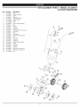
Parts List ...................................................
Service Numbers .....................................
Attention is ALERT:
required inIndicates
order to avoid
personal
injury.
SAFETY
danger,serious
warning
or caution.
May be used in conjunction with other symbols or pictographs.
2
Warranty ....................................................
Know Your Unit ...............................................
injury
to yourself
or to to
others.
thewill
safety
precautions
DANGER:
Failure
obey Always
a safety follow
warning
result
in serious
to reduce the risk of fire, electric shock and personal injury.
injury to yourself Failure
and others.
Always
follow
the safety
precautions
WARNING:
to obey
a safety
warning
can result
in
to reduce the risk of fire, electric shock and personal injury.
_IL
10
11
30
Back Cover
NOTE:
NOTE=
NOTE
NOTE: For users on U.S. Forest Land and in the states of California, Maine,
Oregon and Washington. All U.S. Forest Land and the state of California (Public
Resources Codes 4442 and 4443), Oregon and Washington require, by law that
certain internal combustion engines operated on forest brush and/or grass-covered
areas be equipped with a spark arrestor, maintained in effective working order, or
the engine be constructed, equipped and maintained for the prevention of fire.
Check with your state or local authorities for regulations pertaining to these
requirements. Failure to follow these requirements could subject you to liability or
a fine. This unit is factory equipped with a spark arrestor. If it requires
replacement, ask your LOCAL SERVICE DEALER to install the Accessory Part
#753=06238 Muffler Assembly.
MEANING
property
damage
or personal
to warning
yourself or
others.in
CAUTION:
Failure
to obey injury
a safety
mayto result
Always follow the safety precautions to reduce the risk of fire,
electric shock and personal injury.
Advises of information or instructions
maintenance of the equipment.
vital to the operation or
This Unit Can Use a Plug-in Power Start or Power Bit Start
Optional Accessory!
Please refer to the Plug-In Power Start or Power Bit Start operator's
manual for proper use of these features. (Items may be Sold
Separately! Please refer to page 9 of this manual for more information
about purchasing these accessories.)
Read the Operator's Manual and follow all warnings and safety instructions.
Failure to do so can result in serious injury to the operator and/or bystanders.
FOR QUESTIONS, CALL 1=800=4=MY=HOME®.
All information, illustrations, and specifications in this manual are based on the
latest product information available at the time of printing. We reserve the right
to make changes at any time without notice.
• iMPORTANT SAFETY iNSTRUCTiONS
READ ALL INSTRUCTIONS
BEFORE OPERATING
followed. Please read these instructions before operating the unit
in order to ensure
the using
safety the
of the
anymust
bystanders.
WARNING:
When
unit,operator
all safetyand
rules
be
Please keep these instructions for later use.
_
• Avoid creating a source of ignition for spilled fuel. Do not start the engine until
fuel vapors dissipate.
J
• Read the instructions carefully. Be familiar with the controls and proper use of
the unit.
Never start or run the unit inside a closed room or building. Breathing exhaust
fumes can kill. Operate this unit only in a well ventilated outdoor area.
Inspect the unit before use. Replace damaged parts. Check for fuel leaks.
Make sure all fasteners are in place and secure. Replace parts that are
cracked, chipped, or damaged in any way. Do not operate the unit with loose
or damaged parts.
Wear safety glasses or goggles that are marked as meeting ANSI Z87.1-1989
standards. Also wear ear/hearing protection when operating this unit. Wear a
face or dust mask if the operation is dusty. Long sleeve shirts are
recommended.
Carefully inspect the area before starting the unit. Remove all debris and hard
or sharp objects such as glass, wire, etc.
Wear heavy, long pants, boots and gloves. Do not wear loose clothing,
jewelry, short pants, sandals or go barefoot. Secure hair above shoulder level.
This unit has a clutch. The tines remain stationary when the engine is idling. If
they do not, have the unit adjusted by a Sears or other authorized service
technician.
Be aware of the risk of injury to the head, hands and feet.
Clear the area of children, bystanders, and pets. At a minimum, keep all
children, bystanders, and pets outside a 50 feet (15 m.) radius; there still may
be a risk to bystanders from thrown objects. Bystanders should be
encouraged to wear eye protection. If approached, stop the unit immediately.
Squeeze the throttle control and check that it returns automatically to the idle
position. Make all adjustments or repairs before using unit.
SAFETY WARNINGS FOR GAS UNITS
_
explode
if ignited.
Take the
following
precautions:
WARNING:
Gasoline
is highly
flammable
and its vapors can
Store fuel only in containers specifically designed and approved for the
storage of such materials.
engine and allow it to cool before filling the fuel tank. Never
of the fuel tank, or add fuel, when the engine is hot. Never
without the fuel cap securely in place. Always loosen the fuel
to relieve any pressure in the tank.
• Add fuel in a clean, well-ventilated outdoor area where there are no sparks or
flames. Do not smoke while fueling. Wipe up any spilled fuel from the unit
immediately. Always wipe unit dry before using.
Move the unit at least 30 feet (9.1 m) from the fueling source and site before
starting the engine. Do not smoke or allow sparks and open flames near the
area while adding fuel or operating the unit.
WHILE OPERATING
Do not operate this unit when tired, ill, or under the influence of alcohol,
drugs, or medication.
Children and teens under the age of 15 must not use the unit, except for
teens guided by an adult.
All guards and safety attachments must be installed properly before operating
the unit.
--
• Always stop the
remove the cap
operate the unit
tank cap slowly
Be sure the tines are not in contact with anything before starting the unit.
i
Use the unit only in daylight or good artificial light.
Avoid accidental starting. Be in the starting position whenever pulling the
starter rope. The operator and unit must be in a stable position while starting.
See Starting/Stopping Instructions.
Use the right tool. Only use this tool for the purpose intended.
Use extreme caution when reversing or pulling the unit backwards.
Do not overreach. Always keep proper footing and balance. Take extra care
when working with on steep slopes or inclines.
• Always
hold
theunitwithbothhands
when
operating.
Keep
afirmgrip
onthe
• Toreduce
firehazard,
keep
theengine
andmuffler
free
fromgrass,
leaves,
handle.
excessive
grease
orcarbon
build
up.
Keep
hands,
face,
andfeetatadistance
from
allmoving
parts.
Donottouch After use
ortrytostopthetines
while
they
arerotating.
Clean the unit with household cleaner to remove any gum buildup. Oil the
Donottouch
theengine
ormuffler.
These
parts
getextremely
hotfrom
tines with machine oil to prevent rust.
operation.
They
remain
hotforashort
time
after
turning
offtheunit.
OTHER SAFETY WARNINGS
Donotoperate
theengine
faster
than
thespeed
needed
forthejob.Donot
Never store a fueled unit inside a building where fumes may reach an open
runtheengine
athigh
speed
when
theunitisnotinuse.
flame or spark.
Always
stoptheengine
when
work
isdelayed
orwhen
walking
fromone
Allow the engine to cool before storing or transporting. Be sure to secure the
location
toanother.
unit while transporting.
Ifstriking
orbecomes
entangled
withaforeign
object,
stoptheengine
Store the unit in a dry area, locked up or up high to prevent unauthorized use
immediately
and
check
fordamage.
Donotoperate
before
repairing
damage. or damage. Keep out of the reach of children.
Donotoperate
theunitwithloose
ordamaged
parts.
Never douse or squirt the unit with water or any other liquid. Keep handles dry,
Stop
andswitch
theengine
tooffformaintenance
orrepair.
clean and free from debris. Clean after each use. See the Cleaning and
Use
only
original
equipment
manufacturer
replacement
parts
andaccessories Storage instructions.
forthisunit.
These
areavailable
from
aSears
orother
authorized
service
Keep these instructions. Refer to them often and use them to instruct other
dealer.
Theuseofanyunauthorized
parts
oraccessories
could
lead
toserious users.
If loaning someone this unit, also loan them these instructions.
injury
totheuser,
ordamage
totheunit,
andvoid
thewarranty.
SAVE THESE INSTRUCTIONS
Keep
unitclean
ofvegetation
andother
materials
thatmaybecome
lodged
or
entangled
intheunit.
= SAFETY & iNTERNATiONAL
This operator's manual describes safety and international symbols and pictographs
complete safety, assembly, operating and maintenance and repair information.
SYMBOL
MEANING
SYMBOLS •
that may appear on this product.
SYMBOL
MEANING
Read the operator's
manual for
CRAFTSMAN
2 YEAR
FULL
WARRANTY
FOR 2 YEARS from the date of purchase, this product is warranted against any defects in material or workmanship.
free replacement if repair is unavailable.
For warranty coverage details to obtain repair or replacement,
visit the web site: www.craftsman.com
Defective product will receive free repair or
This warranty covers ONLY defects in material and workmanship.
Warranty coverage does NOT include:
•
Expendable items that can wear out from normal use within the warranty period, such as blades, tines or belts.
Product damage resulting from user attempts
at product modification
or repair or caused by product accessories.
Repairs necessary because of accident or failure to operate or maintain the product according to all supplied instructions.
Preventive maintenance, or repairs necessary due to improper fuel mixture, contaminated or stale fuel.
This warranty is void if this product is ever used while providing commercial
services or if rented to another person.
This warranty gives you specific legal rights, and you may also have other rights, which vary from state to state.
Sears Brands Management Corporation, Hoffman Estates, IL 60179
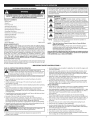
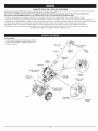
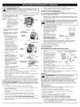
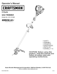
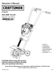
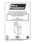
APPLiCATiONS
• Cultivating
Cultivating
sod and light to medium soil
in garden areas, around trees, etc.
Edging
Throttle
Control
Handlebar
Knobs
Spa
Muffler
\
Starter Rope
Gri
Tine
Guard
Fuel
Cap
Oil Fill Plug
Wheel
Support
Bracket
Cultivator
Tines St
Air Filter
Cover
Primer Bulb
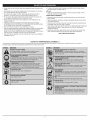
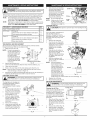
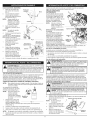
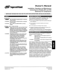
POSiTiONiNG
HANDLEBARS
THE
4.
1.
Loosen the two knobs on the
inside of the handlebars (Fig. 1).
2.
With the unit upright, swing
the handlebars up into the
operating position (Fig. 2).
NOTE:
3.
Handlebar Knob
_
/
Take care not to pinch
the throttle cable or
switch wires when
positioning the
handlebar.
Bolt
Wipe up any oil that may
have spilled and reinstall the
oil fill plug.
Check oil before each use and
change as needed. Refer to
Checking the Oil Level.
RECOMMENDED
FUEL TYPE
Do not over-tighten
knobs.
OimFimlPlug
5.
Washe I
Fig. 1
Tighten the knobs to secure
the handlebars in place.
NOTE:
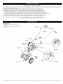
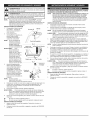
Pour the entire bottle of oil into
the oil fill hole (Fig. 5).
NOTE:
Never add oil to the fuel
or fuel tank.
the
O-Ring
oi_ Fill
Hole
Old fuel is the primary reason for
improper unit performance. Be
sure to use fresh, clean, unleaded gasoline.
Fig. 6
NOTE:
to Federal, State and
Dispose of the old gasoline in accordance
Local regulations.
4.
Reconnect the spark plug
wire to the spark plug.
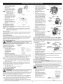
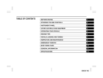
ADJUSTING TINE DEPTH
NOTE:
To adjust the wheel support
bracket proceed as follows:
1.
Stop engine and disconnect
spark plug to avoid
accidental starting.
Today's fuels are often a blend of gasoline and oxygenates such as ethanol,
methanol or MTBE (ether). Alcohol-blended fuel absorbs water. As little as 1%
water in the fuel can make fuel and oil separate or form acids when stored.
Use fresh fuel (less than 60 days old), when using alcohol-blended fuel.
2.
3.
4.
This is a four cycle engine. In order to avoid damage to the unit, do
not mix oil with gasoline.
Definition of Blended Fuels
Fig. 2
Remove clip from the cotter
pin and slide clevis pin out of
tailpiece bracket (Fig. 3).
Slide the wheel support
bracket up or down in the
tailpiece, aligning the holes
to the desired tine depth.
Wheem
Bracket
Wheel Support
Bracket
Using Blended Fuels
If choosing to use a blended fuel, or its use is unavoidable,
recommended precautions:
• Always use fresh unleaded gasoline
follow
• Use the fuel additive STA-BIL® or an equivalent
Cotter
• Drain tank and run the engine dry before storing unit
Pin
Using Fuel Additives
Place the cotter pin through
the hole and secure with clip.
WARNING:
i_
Fig. 3
ii
Gasoline is extremely flammable.
Ignited vapors
may explode. Always stop the engine and allow it to cool before
filling the fuel tank. Do not smoke while filling the tank. Keep
sparks and open flames at a distance from the area.
i
WARNING:
i_
WARNING:
OVERFILLING OIL CRANKCASE MAY CAUSE
SERIOUS PERSONAL INJURY. Check and maintain the proper oil
level in the crankcase; it is important and cannot be
overemphasized. Check the oil before each use and change it as
needed. See Changing the Oil.
RECOMMENDED
OiL TYPE
Using the proper type and weight of oil in the crankcase is extremely important.
Check the oil before each use and change the oil regularly. Failure to use the
correct oil, or using dirty oil, can cause premature engine wear and failure.
Use a high-quality SAE 30 weight oil of API (American Petroleum Institute)
service class SF, SG, SH.
ADDING OiL TO CRANKCASE:
iNiTiAL USE
NOTE:
This unit is shipped
without oil. In order to
avoid damage to the
unit, put oil in the
crankcase before
attempting to start the
unit.
2.
3.
Unscrew the top of the bottle
of oil and remove the paper
seal covering the opening.
Replace the top. Next, cut the
tip off the funnel spout (Fig. 4).
Place unit on a flat, level
surface.
outdoor area. Wipe
The use of fuel additives, such as STA-BIL® Gas Stabilizer or an equivalent, will
inhibit corrosion and minimize the formation of gum deposits. Using a fuel additive
can keep fuel from forming harmful deposits in the carburetor for up to six (6)
months. Add 0.8 oz. (23 ml.) of fuel additive per gallon of fuel according to the
instructions on the fuel additive container. NEVER add fuel additives directly to the
unit's gas tank.
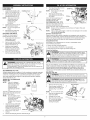
FUELING THE UNIT
_
spray.
Never operate
the fuel
unit cap
without
capinjury
securely
place.
WARNING:
Remove
slowlythetofuel
avoid
from infuel
_
been proven that fuel containing greater than 10% ethanol will
WARNING:
DO engine
NOT USE
IN THiS UNIT. It has
likely damage this
and E85
void FUEL
the warranty.
1.
Remove the fuel cap (Fig. 7).
Gas Can Spout
2.
Place the gas container's
spout into the fill hole on the
fuel tank (Fig. 7) and fill the
tank.
NOTE:
Do not overfill the tank.
The unit is supplied with one 3.04
fluid oz. (90 ml.) bottle of SAE 30
SF, SG, SH oil (Fig. 4).
NOTE:
Save the bottle of oil. It
can be used to measure
the correct amount
during future oil
changes. See Changing
the Oil.
1.
1
1
Add fuel in a clean, well ventilated
up any spilled fuel immediately. Avoid creating a source of ignition for
spilt fuel. Do not start the engine until fuel vapors dissipate.
Fig. 4
oimFilmHome
Remove the oil fill plug from the crankcase (Fig. 6).
Fig. 5
3.
Wipe up any gasoline that
may have spilled.
4.
5.
Reinstall the fuel cap.
Move the unit at least 30 ft.
(9.1 m) from the fueling
source and site before
starting the engine.
Tank
Fig. 7
m
i iwA°°,°o
o0eratethisunitonyinawe
ventiatedoutdoorarea
Carbon monox de exhaust fumes can be ethan
a conf ned area.
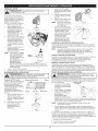
NOTE=
starting position when pulling the starter rope (Fig. 10). To avoid serious
ARNING:
Avoid accidental starting. Make sure to be in the
n ury, the operator and un t must be n a stab e post on wh e start rig. j
_
NOTE:
This unit uses the Incredi=PulF M starting system, which
significantly reduces the effort required to start the engine. There is
no harsh resistance when pulling the starter rope. Be aware that
this starting method is vastly different from (and much easier than)
previous starting
techniques.
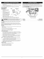
STARTING INSTRUCTIONS
OFF (O)
ON ( I )
1.
Check the oil level in the
crankcase. Refer to
Checking the Oil Level.
2.
Fill the fuel tank with fresh,
clean unleaded gasoline.
Refer to Fueling the Unit.
NOTE:
There is no need to turn
the unit on. The On/Off
Control is in the ON (I)
position at all times
(Fig. 8).
3.
Throttle
Fully press and release the primer bulb 10 times, slowly. Some amount
of fuel should be visible in the primer bulb (Fig. 9). If fuel can not be seen
in the bulb, press and release the bulb until fuel is visible.
NOTE:
Make sure to always have the unit tilted back slightly to bring the
tines off the ground when starting.
Control
4.
Fig. 8
Weather
Primer
Starter Lever
Bulb
5.
_
IU
6.
Lever (Fig. 9) back to the
closed position and
continue to step 3. DO
NOT
flipCold
this Weather
lever back
if
flip the
Start
3.
40°Rthe
temperature is above
Fully press and release the
primer bulb 10 times, slowly.
Some amount of fuel should
be visible in the primer bulb
(Fig. 9). If fuel can not be
seen in the bulb, press and
release the bulb until fuel is
visible.
NOTE:
Make sure to always
have the unit tilted back
slightly to bring the tines
off the ground when
starting.
4.
5.
1.
Check the oil level in the crankcase. Refer to Checking the Oil Level.
2.
Fill the fuel tank with fresh, clean unleaded gasoline. Refer to Fueling the Unit.
NOTE:
There is no need to turn the unit on. The On/Off Control is in the
ON (I) position at all times (Fig. 8).
IF COLD... For cold weather conditions (below 40°F), flip the Cold Weather
Start Lever (Fig. 9) down to the start/closed position and continue to
step 3. DO NOT flip this lever down if the temperature is above 40°R
Cold
conditions (below 40°F),
IFCOLD...
For cold weather
This Unit Can Use a Plug-in Power Start or Power Bit Start
Optional Accessory!
Please refer to the Plug-In Power Start or Power Bit Start operator's
manual for proper use of these features. (Items may be Sold
Separately! Please refer to page 9 of this manual for more information
about purchasing these accessories.)
STARTING INSTRUCTIONS
Hold the handlebar with one hand. Place the Plug-In Power Start or
Power Bit Start into the back of the unit. Refer to Operation section of
the Plug-In Power Start or Power Bit Start operator's manual.
Do Not squeeze the throttle control, press and hold the Plug-In Plug-In
Power Start or drill's ON (I) button for 2 second intervals until unit starts.
Once the unit starts, remove the Plug-In Power Start or drill from the
rear of the unit and wait 60 seconds.
IF COLD... For cold weather conditions (below 40°F), flip the Cold Weather
Start Lever forward to the open position after the unit has started
and before squeezing the throttle control.
7.
Open _
_
Closed
Fig. 9
Starting
Position
"'
Squeezing the throttle control for an additional 30 to 60 seconds to let the
engine warm up. The unit may be used during this time.
iF...
The engine does not start, go back to step 3.
IE..
The engine stops while squeezing
STOPPING INSTRUCTIONS
the throttle, go back to step 4.
1.
Release the throttle control and allow the engine to cool down by idling.
2.
Press and hold the On/Off Control in the OFF (O) position until the unit
comes to a complete stop. (Fig. 8)
./4_/',
Starter
Rope
Hold the handlebar with one
hand and grab the starter
rope with the other hand, do
not squeeze the throttle
Fig. 10
control (Fig. 10). Using one foot to hold down the cultivator.
starter rope 5 times.
Once the unit starts, wait 60 seconds.
OPERATING
-L_
6.
Squeezing the throttle control for an additional 30 to 60 seconds to let the
engine warm up. The unit may be used during this time.
IF...
The engine does not start, go back to step 3.
IF...
The engine stops while squeezing the throttle, go back to step 4.
STOPPING INSTRUCTIONS
1.
Release the throttle control and allow the engine to cool down by idling.
2.
Press and hold the On/Off Control in the OFF {O) position until the unit
comes to a complete stop. (Fig. 8)
carry
the unit while
the engine
is running.
ARNING:
To prevent
serious
personal injury, never pick-up or
1.
Move the cultivator to the work area prior to starting the engine.
Transport the cultivator by pushing or
pulling it along on its wheels.
2.
Start the unit by following the Starting
Instructions.
3.
With the engine running and the tines off
the ground, depress the throttle control
to increase the engine speed.
4.
While holding the upper handle with
both hands, slowly lower the cultivator
until the tines make contact with the
ground (Fig. 11).
5.
As cultivating action begins, tilt the cultivator
Fig. 11
up slightly using the handle so that the tines can penetrate the ground.
6.
Once the ground has been broken, continue at a moderate
7.
If the tines are digging too deep or not deep enough, adjust the wheel
bracket as described in Adjusting Tine Depth.
Pull the
IF COLD... For cold weather conditions (below 40°F), flip the Cold Weather
Start Lever forward to the open position after the unit has started
and before squeezing the throttle control.
TIPS
I A
I WARNING:caution
when reversing
To preventor serious
pulling
TRANSPORTING
i _lb
1
pace.
the
personal
unit backwards.
injury, use extreme
1
THE UNIT
engine when operation is delayed or when transporting the unit
i WARNING:
T° prevent seri°us pers°nal injury, always st°p the 1
from one location to another.
1.
Stop the engine.
2.
3.
Tilt the unit back until the tines clear the ground.
Push or pull the unit to the next location to be cultivated.
MAINTENANCE
SCHEDULE
I
6.
or repairs
with unit
running. serious
Always injury,
servicenever
and perform
repair a cool
unit.
ARNING:
To prevent
maintenance
_
i
Perform these required maintenance procedures at the frequency stated in
the table. These procedures should also be a part of any seasonal tune-up.
NOTE:
Some maintenance procedures may require special tools or skills. If
unsure about these procedures take the unit to Sears or other qualified
service dealer. Call 1=800-4-MY=HOME® for more information.
NOTE:
NOTE:
Make sure the O-ring is
in place on the oil fill
plug when checking and
changing the oil (Fig. 15).
CHANGING THE OIL
Maintenance, replacement, or repair of the emission control devices
and system may be performed by a Sears or other qualified service
dealer. Call 1=800=4-MY=HOME® for more information.
FREQUENCY
MAINTENANCE
Every 10 hours
Clean air filter
p. 8
At 10 hours
Change oil
p. 7
Check rocker arm to valve clearance and adjust
Check spark plug condition and gap
p. 8
p. 9
Change oil
Check rocker arm to valve clearance and adjust
p. 7
p. 8
Check spark plug condition and gap
p. 9
Clean spark arrestor
p. 9
Every 40
REQUIRED
--
SEE
_
TINE REMOVAL AND REPLACEMENT
All tines should be replaced at the same time as they will wear evenly
through normal use. Work on one side at a time.
1.
Make sure the unit is off.
Hubs
NOTE:
2.
3.
It may be necessary to
lay the cultivator back in
a horizontal position on
a flat level surface with
the upper handle
touching the ground. It
may also be necessary
to wash any dirt off the
tines and shaft for ease
of removal.
Click
d_
c
Convex
Side
/1€
--
/4
DirectionOf Convex Sides
Fig. 12
Remove the click pin from
each end of the tine shaft. Slide the tines off of the shaft (Fig. 12).
Clean and oil the shaft.
4.
Slide on the new tines with the hubs facing each other (Fig. 12).
NOTE:
Each tine has a convex side. Make sure that all of the convex
sides are facing as shown in Figure 12.
5.
Secure the new tines to the shaft with click pins. It may be necessary to
wash the dirt off the tines and shaft for ease of removal.
CHECKING
-_
THE OIL LEVEL
unitARNING:
off and allow
to cool
beforepersonal
cleaninginjury,
or maintaining
To itavoid
serious
always turnit. the
The importance of checking and
maintaining the proper oil level in
the crankcase cannot be
overemphasized. Check oil before
each use:
1.
2.
4.
5.
Fig. 13
Fig. 14
Oil Fill
Hole
Fig. 15
6.
Reconnect the spark plug boot.
AIR FILTER MAINTENANCE
unitARNING:
off and allow
to cool
beforepersonal
cleaninginjury,
or maintaining
To itavoid
serious
always turnit.the
Clean and re-oil the air filter every
10 hours of operation. It is an
important item to maintain. Failure
to maintain the air filter properly
can result in poor performance or
can cause permanent damage to
the engine.
1.
Oil Max Fill Line
O-Ring
Wear gloves to prevent injury when handling the unit.
Cleaning the Air Filter
Stop the engine and allow oil
to drain into the crankcase.
Place the unit in a horizontal
Keep dirt, grass clippings
and other debris out of the
engine. Clean the area
around the dipstick before
removing it.
Remove the oil fill plug.
Look into the oil fill hole, use
a flashlight if needed. The oil
should be just touching the
inner most thread (Fig. 14).
i
CAUTION"
Oil Fill Plug
For a new engine, change the oil
after the first 10 hours of
operation. Change the oil while
the engine is still warm. The oil will
flow freely and carry away more
impurities.
1.
Remove the oil fill plug.
2.
Pour the oil out of the oil fill
hole and into a container by
tipping the unit to a vertical
Fig. 16
position (Fig. 16). Allow
ample time for complete
drainage.
3.
Wipe up any oil residue on
the unit and clean up any oil
that may have spilled.
Dispose of the oil according
to Federal, State and local
regulations.
4.
Refill the crankcase with
Fig. 17
3.04 fl.oz. (90 ml) of SAE 30
SF, SG, SH oil.
NOTE:
Use the bottle and
spout saved from initial
use to measure the
correct amount of oil.
Fill Line
The top of the label on
the bottle measures
approximately 3.04
fi.oz. (90 ml) (Fig. 18).
Check the level, See
Checking the Oil Level.
Fig. 18
If the level is low, add a
small amount of oil and recheck. Do not overfill (Fig. 14).
5.
Replace the oil fill plug.
_L_
position to get a proper oil
level reading (Fig. 13).
3.
If the oil level is not touching
the inner most thread on the
oil fill hole, add a small
amount of oil to the oil fill hole
and recheck (Fig. 17). Repeat
this procedure until the oil
level reaches the inner most
thread on the oil fill hole.
NOTE:
Do not overfill the unit.
Open the air filter cover. Push
the tab on the under side of
the cover inward. Then pull
the air filter cover out and up.
(Fig. 19).
2.
Remove the air filter (Fig. 19).
3.
Wash the filter in detergent
and water (Fig. 20). Rinse the
filter thoroughly and allow it
to dry.
Air Filter Cover
Tab
Slot
Hooks
Fig. 19
Fig. 20
Air Filter
i
4.
Apply enough clean SAE 30
motor oil to lightly coat the
filter (Fig. 21).
Squeeze the filter to spread
and remove excess oil (Fig. 22).
Replace the filter (Fig. 19).
5.
6.
NOTE:
Operating the unit
without the air filter, will
VOID the warranty.
Reinstall the air filter cover.
Position the slots on the top
of the air filter cover onto the
tabs at the top of the back
plate (Fig. 19).
7.
8.
4.
Remove the engine cover
(Fig. 24).
5.
Clean dirt from around the
rocker arm cover. Remove the
screw holding the rocker arm
cover with a large flat blade
screwdriver or Torx T-25 bit
(Fig. 25). Remove the rocker
arm cover and gasket.
6.
Pull the starter rope slowly to
bring the piston to the top of
its travel, (known as top dead
center). Check that:
• The piston is at the top of its
travel. This should be done by
looking into the spark plug hole.
(Fig. 25)
Fig. 21
Swing the cover down until
the tab on the air filter
backplate snaps into place in
the slot on the air filter cover
(Fig. 19).
iDLE SPEED ADJUSTMENT
The idle speed of the engine is
Fig. 22
adjustable. An idle adjustment screw is between the air filter cover and the
engine starter housing (Fig. 23).
NOTE:
Careless adjustments can seriously damage the unit. Aside from
idle speed, only a Sears or other qualified service dealer should
make carburetor adjustments.
First, Check
Second, Clean Air Filter
adjustments. Wear protective clothing and observe all safety
ARNING:to prevent
The cutting
attachment
spin during idle speed
instructions
serious
personal may
injury.
If, after checking the fuel and
cleaning the air filter, the engine
still will not idle, adjust the idle
speed screw as follows:
1.
2.
Idle Adjustment
Screw
• To increase clearance, turn
the adjusting nut
counterclockwise.
9.
10.
1.
• the engine hesitates or stalls on acceleration
there is a loss of engine power
ROCKER ARM CLEARANCE
_L_
J
2.
i-""_n._
'/
Feemer
(0.076-0.152mm)_
_Valve
Fig. 27
Stem
Reinstall the rocker arm cover using a new gasket. Torque the screw to
20-30 inoib (2.2-3.4 Norn).
Check the spark plug and reinstall. See Replacing the Spark Plug.
Stop the engine and allow it to cool. Remove the six (6) screws on the back
of the engine cover with a Flat-head or T-25 Torx screwdriver (Fig. 24).
electrodes.
Grit Do
in the
couldscrape
damage
the cylinder.
ARNING:
not engine
sand blast,
or clean
spark plug
3.
Grasp the plug wire firmly
and pull the cap from the
spark plug.
Clean dirt from around the
spark plug. Remove the spark
plug from the cylinder head by
turning a 5/8 in. socket
counterclockwise.
4.
Replace cracked, fouled or
This requires disassembly of the engine. If unsure or unqualified to perform this,
take the unit to a Sears or other qualified service dealer.
Inspect the valve to rocker arm clearance with a feeler gauge after
the first 10 hours of operation and every 40 hours of operation.
The engine must be cold when checking or adjusting the valve clearance.
0.003-0.006
Use a replacement Champion
® #RDZ4H
spark plug. The correct air gap
is 0.025 in. (0.635 turn). Remove the plug after every 40 hours of operation
and check its condition.
• the engine will not idle
• This task should be performed inside, in a clean, dust free area.
1.
Remove the six (6) screws on the back of the engine cover with a Flathead or T-25 Torx screwdriver (Fig. 24).
Fig. 26
Replace the spark plug wire.
Reinstall the engine cover. Check alignment of the cover before tightening
the screws. Tighten screws.
REPLACING THE SPARK PLUG
If the cutting attachment rotates when the engine idles, turn the idle
speed screw counterclockwise
1/8 of a turn at a time (as needed), to
reduce idle speed.
Checking the fuel, cleaning the air filter, and adjusting the idle speed should
solve most engine problems. If not and any of the following are true have the
unit serviced by a Sears or other qualified service dealer:
NOTE:
EXHAUST
11.
12.
should not rotate when the engine idles.
unitARNING:
off and allow
to cool
beforepersonal
cleaninginjury,
or maintaining
To itavoid
serious
always turnit. the
Nuts
INTAKE
• To decrease clearance, turn
the adjusting nut clockwise.
b.
Recheck both clearances,
and adjust as necessary.
3.
_
Adjusting
1
Release the throttle trigger
Fig. 23
and let the engine idle. If the
engine stops, insert a small phillips in between the Air Filter Cover and
the Engine Cover (Fig. 23). Turn the idle speed screw in, clockwise, 1/8
of a turn at a time (as needed) until the engine idles smoothly.
The cutting attachment
Fig. 25
The recommended clearance for both intake and exhaust is .003 - .006 in.
(.076 - 0.152 rnrn). Use a standard automotive .005 in. (0.127 mm) feeler
gauge. The feeler gauge should slide between the rocker arm and valve stem
with a slight amount of resistance, without binding. See Figures 26 and 27.
8. If the clearance is not within
specification:
Exhaust
Rocker Arm
Adjusting
a.
Turn the adjusting nut using a
Nut
5/16 inch (8 mm) wrench or
nut driver (Fig. 27).
Start the engine and let it run
at a high idle for a minute to
warm up. Refer to
Starting/Stopping
Instructions.
NOTE:
Spark Pluq
Hole
If these statements are not true,
repeat step 6.
Rocker
7.
Slide the feeler gauge between
Arms
the rocker arm and the valve
return spring. Measure the
clearance between the valve
stem and rocker arm (Fig. 27).
Measure both the intake and exhaust valves.
Fuel
The condition of the air filter is important to the operation of the unit. A dirty
air filter will restrict air flow. This is often mistaken for an out of adjustment
carburetor. Check the condition of the air filter before adjusting the idle
speed screw. Refer to Air Filter Maintenance.
Third, Adjust Idle Speed Screw
Rocker Arm
Cover
• Both rocker arms move freely,
and both valves are closed
Old fuel is usually the reason for improper unit performance. Drain and refill
the tank with fresh fuel prior to making any adjustments. Refer to Oil and
Fuel Information.
_L_
View of the Rear Engine Cover
Disconnect the spark plug wire.
Clean dirt from around the
spark plug. Remove the spark
plug from the cylinder head by
Screws
turning a 5/8 in. socket
Screws
counterclockwise.
2.
3.
I
0.025 in.
(0.635 ram)
t
Fig. 28
I
PLUG=IN POWER START AND POWER BIT START FEATURES
dirty spark plug. Set the air gap at 0.025 in. (0.635 ram} using a feeler
gauge (Fig. 28).
5.
Install a correctly-gapped
spark plug in the cylinder head. Turn the 5/8
in. socket clockwise until snug.
If using a torque wrench torque to: 110=120 in.olb. (12.3-13.5
Do not over=tighten.
SPARK ARRESTOR
MAINTENANCE
Muffler
Norn}
Spark Arrestor
Screen
cover. See Rocker Arm
2.
1.
3.
Cover
Clearance.
With a flat blade screwdriver
Remove
the rear
engine
or Torx T-2O
bit and
a T-25
"_
bit, removethethespark
screws
attaching
arrestor
cover to the muffler (Fig. 29).
Slot
_
_
/
1"-25
Screw
_/,
Jr /
_/
1-20 Screw _
4.
Pull the tab on the spark
Fig. 29
arrestor cover out of the
muffler. Remove the spark arrestor cover.
Remove the spark arrestor screen from the spark arrestor cover.
5.
Clean the spark arrestor screen with a wire brush or replace it.
m
I A
I WARNING:
Electric
To avoid serious personal injury, always turn the
_ unit off and allow it to cool before cleaning or maintaining
it.
6.
Reinstall the spark arrestor screen, spark arrestor cover and screws.
CLEANING
Use a small brush to clean off the outside of the unit. Do not use strong
detergents. Household cleaners that contain aromatic oils such as pine and
lemon, and solvents such as kerosene, can damage plastic housing or handle.
Wipe off any moisture with a soft cloth.
STORAGE
Never store the unit with fuel in the tank where fumes may reach an open
flame or spark.
Allow the engine to cool before storing.
Lock up the unit to prevent unauthorized use or damage.
• Store the unit in a dry, well-ventilated area.
Store the unit out of the reach of children.
LONG TERM STORAGE
1.
Drain all gasoline from the gas tank into a container. Do not use gas
that has been stored for more than 60 days. Dispose of the old gasoline
in accordance to Federal, State, and Local regulations.
2.
Start the engine and allow it to run until it stalls. This ensures that all
gasoline has been drained from the carburetor.
3.
Allow the engine to cool. Remove the spark plug and put 5 drops of
high quality motor oil into the cylinder. Pull the starter rope slowly to
distribute the oil. Reinstall the spark plug.
NOTE:
4.
This unit is designed to be started with an optional Plug-In Power Start or
Power Bit Start that are sold separately. If choosing to start the unit using
one of these features or have questions please contact your local retailer or
call 1-800-4=MY-HOME®,
for more information and purchasing. You may
also go to www.craftsman.com.
Remove the spark plug and drain all of the oil from the cylinder
before attempting to start the unit after storage.
Change the oil, referring to Changing the Oil. Dispose of the old oil in
accordance to Federal, State and Local regulations.
5.
Thoroughly clean the unit and inspect for any loose or damaged parts.
Repair or replace damaged parts and tighten loose screws, nuts or
bolts. The unit is ready for storage.
TRANSPORTING
Allow the engine to cool before transporting.
Secure the unit while transporting.
Drain the gas tank before transporting.
Tighten gas cap before transporting.
]
Item No.
316.85951
316.85952
.....................................
........................................
Start
Feature
Description
Plug-In Power Start
Power Bit Start
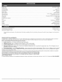
PROBLEM
SOLUTION
Empty fuel tank
Fill fuel tank with fuel
Primer bulb wasn,t pressed en0ugh
"Press
primer bulb fully and Slowly i0 timeS
Old fuel
Drain gas tank and add fresh fuel
Plugged spark arrestor
cOld
weather
start LeVer in the closed position
Clean or replace spark arrestor
"
Move cOld Weather start Lever to open position
]iiiiiiii
......
Air filter is plugged
Replace or clean the air filter
oJd fuel
Drain gas tank and add fresh fue!
Improper idle speed
Adjust according
to the Idle Speed Adjustments
section.
m
Old fuel
Drain gas tank and add fresh fuel
improper carburetoi
cultivator
adjustment
Take to Sears or other qualified service dealer for an adjustment
tines bound with dirt or grass
Dirty air filter
Stop the enginel clean and remove any debris binding the tines
Clean or replace the air filter
Plugged spark arrestor
Clean or replace spark arrestor
,
Old fuel
mproper carburetor
Drain gas tank and add fresh fuel
adjustment
Take to Sears or other qua fed serv ce des er for an adjustment
Fouled spark plug
Replace or clean the spark plug
Plugged spark arrestor
Clean or replace spark arrestor
10
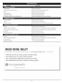
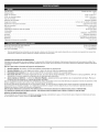
Engine Type ....................................................................................................
Displacement
..............................................................................................................
Operating
Air-Cooled, 4-Cycle
29 cc
RPM ........................................................................................................
6,800+ rpm
Idle Speed RPM ..................................................................................................
Ignition Type ............................................................................................................
Ignition Switch
2,800 - 3,600 rpm
Electronic
......................................................................................................
Rocker Switch
Valve clearance ......................................................................................
Spark Plug Gap ...............................................................................................
0.003-0.006
Spark Plug ........................................................................................
Lubrication ............................................................................................................
Champion
in. (0.076-0.152 mm)
0.025 inch (0.635 mm)
RDZ4H or equivalent plug
SAE 30 Oil
Crankcase Oil Capacity ...............................................................................................
Fuel ..................................................................................................................
3.04 oz (90 ml)
Unleaded
Carburetor ..................................................................................................
Starter ..............................................................................................................
Muffler
Diaphragm, All-Position
Auto Rewind
.........................................................................................................
Baffled with Guard
Throttle ......................................................................................................
Fuel Tank Capacity ...................................................................................................
Cultivating
Path Width (Maximum)
Manual Spring Return
14 oz (414 ml)
..................................................................................
9 inches (22.86 cm)
Cultivating Depth (Maximum) ......................................................................................
Approximate Weight (no fuel) ..........................................................................................
*
All specifications
notice.
are based on the latest product information
REPAIR PROTECTION
6 inches (15.24 cm)
25 lb. (11.5 kg)
available at the time of printing. We reserve the right to make changes at any time without
AGREEMENTS
Congratulations on making a smart purchase. Your new Craftsman@ product is designed and manufactured for years of dependable operation.
products, it may require repair from time to time. That's when having a Repair Protection Agreement can save you money and aggravation.
Here is what the Repair Protection
[]
Expert
service
[]
Unlimited
[]
Product
[]
Discount
preventive
by our 10,000
service
Plan Agreement
professional
and no charge
replacement
of 10% from
maintenance
up to $1500
for parts
if your
But like all
includes:
repair
specialists
and labor
covered
regular price of service
checks
on all covered
product
and related
repairs
can not be fixed
installed
parts not covered
by the agreement;
also,
10% off regular
price of
[]
Fast help by phone - we call it Rapid Resolution
- phone support from a Sears representative.
Think of us as a "talking owner's manual."
Once you purchase the Repair Protection Agreement, a simple phone call is all that it takes for you to schedule service. You can call anytime day or night, or
schedule a service appointment online.
The Repair Protection Agreement is a risk-free purchase. If you cancel for any reason during the product warranty period, we will provide a full refund. Or a prorated
refund anytime after the product warranty period expires. Purchase your Repair Protection Agreement today!
Some limitations and exclusions apply. For prices and additional information call 1=800=827=6655.
*Coverage in Canada varies on some items. For full details call Sears Canada at 1 =800=361 =6665.
Sears installation Service
For Sears professional installation of home appliances, garage door openers, water heaters, and other major home items, in the U.S.A. or Canada call 1-800-4-MY-HOME ®.
11
12
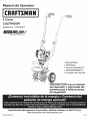
Manual del Operador
M
4 Ciclos
CULTIVADOR
Modelo No. 316.299371
INCREDI.PULL. UJ-t
TM
UNBELIEVABLE
STARTING
E A S E
TM
*
*
*
*
*
SEGURIDAD
MONTAJE
FUNCIONAMIENTO
MANTENIMIENTO
LISTADO DE PIEZAS
PRECAUCION: Lea el manual
del operador y siga todas ias
advertencias
e instrucciones
de seguridad.
Sears Brands
Management
Visite
P/N 769=06627 PO0
Corporation,
nuestro
Hoffman
Estates,
IL 60179 U.S.A.
sitio web: www.craftsman.com
11/10
PROPOSICION
65 DE CALiFORNiA
Toda la informaci6n, las ilustraciones y las especificaciones contenidas en este
manual se basan en la informaci6n mAs reciente disponible en el momento de
impresi6n del manual. Nos reservamos el derecho de hacer cambios en
cualquier momento sin aviso previo.
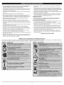
Los simbolos de seguridad se utilizan para Ilamar su atenci6n sobre posibles peligros. I
Los simbolos de seguridad y sus explicaciones merecen toda su atenci6n y_
comprensi6n. Los simbolos de seguridad no eliminan ningL_npeligro per si mismos.
Las instrucciones o advertencias que ofrecen no substituyen las medidas adecuadas
de prevenci6n de accidentes.
J
LAS EMISIONES DEL MOTOR DE ESTE PRODUCTO CONTIENEN
SUBSTANCIAS QUIMICAS QUE EL ESTADO DE CALiFORNiA CONOCE
COMO CAUSANTES DECANCER, DEFECTOS DE NACIMIENTO U OTROS
DANOS REPRODUCTIVOS.
INDICE DE CONTENIDOS
SIMBOLO
Normas para una operaci6n segura ..............................
Garantia ...................................................
Conozca su unidad ...........................................
14
16
16
Instrucciones
17
Informaci6n
de ensamble
.....................................
del aceite y del combustible
..........................
de arranque y apagado ............................
de operaci6n
....................................
18
19
Instrucciones
de mantenimiento
19
......................
Limpieza y almacenamiento
....................................
Accesrorio Opcional ..........................................
22
22
Resoluci6n de problemas
23
......................................
Especificaciones
.............................................
Lista de piezas ................................................
Numeros de servicio
................................
precauci6n. DE
DebeSEGURIDAD:
prestar atenci6n
ALERTA
para
evitar
sufrir advertencia
graves lesiones
Indica
peligro,
o
personales. Puede ser utilizado junto con otros simbolos o figuras.
17
Instrucciones
Instrucciones
y reparaci6n
puede
que
usted u otras
personas sufran
graves
PELIG conducir
RO: Elano
obedecer
una advertencia
de seguridad
lesiones. Siga siempre las precauciones de seguridad para reducir
el riesgo de incendio, descarga el6ctrica y lesiones personales.
puede conducir a que
ADVERTENOIA:
usted
u otrasuna
personas
sufrandelesiones.
El
no seguir
advertencia
seguridad
Siga siempre las precauciones de seguridad para reducir el
riesgo de incendio, descarga el6ctrica y lesiones personales.
_,
23
PRECAUCION:
El no seguir una advertencia de seguridad
puede conducir a daSo patrimonial o a que usted u otras personas
sufran lesiones personales. Siga siempre las precauciones de
seguridad para reducir el riesgo de incendio, descarga el6ctrica y
lesiones personales.
Contraportada
PARACHISPAS
NOT.&:Para los usuarios en tierras forestales de los EE.UU. y en los estados de
California, Maine, Oregon y Washington. Todos los terrenos forestales de los EE.UU.
y el estado de California (C6digos de Recursos PQblicos 4442 y 4443), Oregon y
Washington, requieren pot decreto, que ciertos motores de combusti6n interna que se
hagan funcionar en zonas boscosas y/o zonas cubiertas por pastizales, esten equipados
con un parachispas, que sean mantenidos en buen estado de funcionamiento o que el
motor sea construido, este equipado y sea mantenido para evitar incendios. Consulte
los reglamentos pertinentes a esos requisitos con las autoridades estatales o locales. El
incumplimiento de esos requisitos puede responsabilizarle o someterle a la imposici6n
de una multa. Esta unidad fue equipada en la fabrica con un parachispas. Si requiere
sustituci6n, hay una Pantalla Parachispas disponible, Pieza # 753-06238 al contactar
el departamento de servicio.
• IMPORTANTE
NOTA:
Le ofrece informaci6n o instrucciones que son esenciales para la
operaci6n o mantenimiento del equipo.
NOTA:
iEsta unidad puede utilizar un comienzo enchufable de la energfa o un
accesorio de arranque opcional comienzo del pedacito de energfa!
Para informarse sobre el uso adecuado de estos sistemas,consulte el manual
del operador del comienzo enchufable de laenergfa de opcional comienzo
del pedacito de energfa.(Sevende por separado) En lapagina 22 de este
manual encontrar_ la informaci6n necesariapara comprar estos accesorios).
Lea el manual del operador y siga todas las advertencias e instrucciones de
seguridad. De no hacerlo, el operador y/o los espectadores pueden sufrir
graves lesiones. Sl TIENE PREGUNTAS, LLAME AL 1=800=4=MY=HOME®
INFORMACION
ANTES DE OPERAR LA UNIDAD
DE SEGURIDAD
•
AVlSOS DE SEGURIDAD PARA LAS UNIDADES QUE FUNCIONAN CON
GASOMNA
R
LEA TODAS LAS INSTRUCCIONES
SIGNIFICADO
[_J
A
seguridad cuando use la unidad. Por favor lea estas instrucciones
para su propia seguridad y las de los espectadores, antes de
hacer
funcionar la unidad.
Por favor
estas reglas
instrucciones
DVERTENCIA:
Se deben
seguirmantenga
las siguientes
de
en un lugar seguro para uso futuro.
• Lea las instrucciones cuidadosamente.
uso adecuado de la unidad.
__
I ADVERTENClA:
La gasolina es muy inflamable y sus gases
Almacene el combustible solamente en recipientes dise_ados y aprobados
especificamente para el almacenamiento de dichos materiales.
Familiaricese con los controles y el
•
• No opere esta unidad cuando est6 cansado, enfermo o bajo la influencia de
alcohol, drogas o medicamentos.
• Los niSos y los adolescentes menores de 15 a5os de edad no deben usar la
unidad. Los adolescentes pueden hacerlo bajo la supervisi6n de un adulto.
Evite crear una fuente de ignici6n para el combustible derramado. No
arranque el motor hasta que se disipen los vapores del combustible.
Todos los dispositivos de protecci6n y los accesorios de seguridad deben
estar instalados adecuadamente antes de operar la unidad.
Pare siempre el motor y deje que se enfrie antes de Ilenar el tanque de
combustible. Nunca quite la tapa del tanque de combustible, ni agregue
combustible, cuando el motor est6 caliente. Nunca opere la unidad sin la
tapa de combustible bien colocada en su lugar. Afloje la tapa del tanque de
combustible lentamente para aliviar cualquier presi6n que haya en el tanque.
Inspeccione la unidad antes de usarla. Reemplace las piezas daSadas.
Verifique si hay fugas de combustible. Asegerese de que todos los fijadores
est6n en su lugar y asegurados. Reemplace las piezas que est6n agrietadas,
astilladas o da5adas en cualquier forma. No opere la unidad con piezas
sueltas o daSadas.
Agregue el combustible en un Area exterior bien ventilada, donde no haya
chispas ni llamas. Quite lentamente la tapa de combustible s61o despues de
haber parado el motor. No fume mientras est6 Ilenando de combustible o
mezclandolo. Limpie de la unidad inmediatamente cualquier combustible
derramado. Seque siempre la unidad antes de usarla.
Inspeccione cuidadosamente el Area antes de operar la unidad. Elimine
todos los escombros y los objetos duros o filosos tales como cristal, alambre,
etc.
Mueva siempre la unida a 30 pies (9.1 m) como minimo de la fuente y sitio de
combustible antes de arrancar el motor. No fume ni permita chispas ni llamas
expuestas cerca del Area mientras est6 agregando combustible u operando
la unidad.
Est6 consciente del riesgo de lesi6n en la cabeza, las manos y los pies.
CUANDO ESTI_ OPERANDO
No permita niSos, espectadores ni mascotas en el Area. Los niSos, los
espectadores y las mascotas deben estar fuera de un radio de 50 pies (15 m.)
como minimo; de todas formas los espectadores correran el riesgo de ser
golpeados por objetos lanzados por la unidad. Se debe exhortar a los
espectadores a que usen protecci6n para los ojos. Si se le acerca alguien
apague la unidad de inmediato.
Oprima el control del estrangulador y compruebe que regresa
automaticamente a la posici6n de marcha en vacio. Haga todos los ajustes o
reparaciones antes de usar la unidad.
14
i
pueden exp otar s se enc enden. Tome as s gu entes precauc ones: |J
.
Nunca arranque ni opere la unidad dentro de un cuarto o ediflcio cerrado.
Respirar los vapores del escape puede ser fatal. Opere esta unidad
solamente en un Area exterior bien ventilada.
.
Use galas protectoras que cumplan con la norma Z87.1-1989 de ANSI y
tengan la marca que Io indica. Use protecci6n para la oreja/audici6n cuando
opere esta unidad. Use mascara facial o para polvo si la operaci6n produce
mucho polvo.
• Use pantalones largos fuertes, botas, guantes y camisa de mangas largas. No
use ropa holgada, joyas, pantalones cortos, sandalias, ni est6 descalzo.
AsegQrese el cabello pot encima del nivel de los hombros.
Pare la unidad, apague el motor y desconecte la bujia para mantenimiento o
reparaci6n.
Use solamente piezas y accesorios de reemplazo del fabricante del equipo
original para esta unidad. Estos estan disponibles en su proveedor de servicio
autorizado. El uso de cualquier pieza o accesorio no autorizado podria causar
lesiones graves al usuario, o dafios a la unidad, y anular su garantia.
Mantenga la unidad limpia de vegetaci6n y otros materiales. Pudieran quedar
obstruidas entre las pQas y el protector.
• Esta unidad tiene un embrague. Las pQas permanece estacionario cuando la
unidad esta en marcha en vacio. Si no sucede asi, haga que un t6cnico de
servicio autorizado ajuste la unidad.
• Antes de arrancar la unidad asegQrese de que las pQas no est6 en contacto
con nada.
• Use la unidad solamente de dia o con buena luz artificial.
Para reducir el peligro de incendio reemplace un silenciador y amortiguador
de chispas defectuoso. Mantenga el motor y el silenciador libre de hierba,
hojas, exceso de grasa o acumulaci6n de carb6n.
DESPUI_S DE USARLA
Evite arranques accidentales. Est6 en la posici6n de arranque cada vez que
hale la cuerda de arranque. El operador y la unidad deben estar en una
posici6n estable al arrancar. Consulte las Instrucciones de Arranque/Parada.
• Use la herramienta correcta. Use esta herramienta solamente para el
prop6sito para el cual fue dise_ada.
• Tenga mucho cuidado cuando invierta o mueva la unidad hacia usted.
• Limpie las pt_as con un limpiador casero para eliminar la acumulaci6n de
resina. Aceite las pQas con aceite de mAquina para evitar la corrosi6n.
OTROS AVISOS DE SEGURIDAD
Nunca almacene una unidad con combustible dentro de un edificio en el cual
los vapores puedan Ilegar a una llama expuesta o una chispa.
No se estire demasiado. Mantenga siempre la base de apoyo y equilibrio
adecuados. Tenga mucho cuidado cuando trabaje en pendientes marcadas o
inclinadas.
Deje que el motor se enfrie antes de almacenarlo o transportarlo.
de fijar bien la unidad mientras la transporta.
Sostenga siempre la unidad con ambas manos cuando la opere. Mantenga
un agarre firme sobre ambas manijas.
Mantenga las manos, la cara y los pies alejados de todas las partes en
movimiento. No toque nitrate de parar los dientes cuando est6n girando.
AImacene la unidad en un area seca y cerrada, o en un lugar alto para evitar
uso no autorizado o dafios. Mant6ngala alejada del alcance de los ni_os.
Nunca rocie ni chorree la unidad con agua ni ningQn otro liquido. Mantenga
las manijas secas, limpias y libres de escombros. Limpiela despues de usarla,
vea las instrucciones de Limpieza y Almacenamiento.
• No toque el motor o el silenciador. Estas piezas estan muy calientes durante
la operaci6n, incluso despues de que se apaga la unidad.
No opere el motor a mAs velocidad de la necesaria para cultivo.
funcionar el motor a alta velocidad cuando no est6 cultivo.
AsegQrese
No haga
• Conserve estas instrucciones. Cons_ltelas con frecuencia y _selas para
instruir a otros usuarios. Si le presta esta unidad a alguien, pr6stele tambien
estas instrucciones.
• Pare siempre el motor cuando deje de cultivo o cuando est6 caminando de un
lugar de cultivo hacia otto.
GUARDE ESTAS INSTRUCCIONES
Si golpea o se enreda con un objeto extrafio, pare el motor inmediatamente y
verifique si ha habido algQn dafio. No Io opere antes de reparar el dafio. No
opere la unidad con piezas sueltas o daRadas.
o SiMBOLOS
DE SEGURIDAD
E INTERNACIONALES
•
Este manual del operador describe los simbolos y figuras de seguridad e internacionales que pueden aparecer en este producto.
3ara obtener informaci6n completa acerca de la seguridad, ensamble, operaci6n y mantenimiento y reparaci6n.
SIMBOLO
SIGNIFICADO
SIMBOLO
|
15
SIGNIFICADO
Lea el manual del operador
GARANTIA
TOTAL
POR 2 ANOS,
DE CRAFTSMAN
Este producto se garantiza DURANTE 2 ANOS a partir de la fecha de compra, contra defectos en el material o en la mano de obra. El producto defectuoso
ser& reparado sin ningOn costo o serA remplazado gratuitamente si no puede ser reparado.
Para conocer los detalles sobre la cobertura de la garantia para que sea reparado o reemplazado,
visite el sitio web: www.craftsman.com
Esta garantia cubre SOLAMENTE defectos en el material o mano de obra. La cobertura de la garantia NO incluye:
• Articulos consumibles que se desgasten debido al uso normal dentro del periodo de la garantia, tales como cuchillas, dientes o correas.
Da_os que ocurran al producto como resultado de intentos de modificaci6n o reparaci6n por parte del usuario, o que sean causados por accesorios del producto.
Reparaciones necesarias debidas a accidente o falla en el funcionamiento,
o por no mantener el producto de acuerdo con todas las instrucciones
El mantenimiento preventivo, o reparaciones necesarias debido a mezcla incorrecta de combustible, o a combustible viejo o contaminado.
Esta garantia es nula si este producto se utiliza alguna vez durante la prestaci6n
Esta garantia le otorga a usted derechos
de servicios de tipo comercial
provistas.
o si se le alquila a otra persona.
legales especificos, y usted puede adem&s poseer otros derechos, los cuales varian de un estado a otro.
Sears Brands Management Corporation, Hoffman Estates, IL 60179
APLICAClONES
Cultivar tierra herbosa y tierra negra ligera a mediana.
Cultivar &reas de jardines, alrededor
• Recortar los bordes.
de &rboles, etc.
Manije en D
Control de encendido
y apagado
Gatiilo del
regulador
Manubrio
Perillas
del
manubrio
Bujia de
encendido
Silenciador
\
Manija de la cuerda
de arranque
Protecci6n
de
las pQas
Tapa del
combustible
Tap6n
del
aceite
Palanca azul del
obturador
_M_nsula
dela
de Soporte
Rueda
PQas
Cubierta
del
filtro
de aire
Bombilla
del
cebador
16
COLOCACION
1.
DEL MANUBRIO
Afloje las dos perillas del
lado interior del manubrio
(Fig. 1).
Perillas dei
manubrio
Verifique el aceite antes de cada uso y cAmbielo cuando sea necesario
segOn se indica en la secci6n de Cambio del aceite.
TIPO DE COMBUSTIBLE
RECOMENDADO
....
Perno
./
2.
Con la unidad en posici6n
vertical, gire el manubrio
hacia arriba hasta la posici6n
de operaci6n (Fig. 2).
NOTA:
Tenga cuidado de no
pellizcar el cable del
regulador o los cables
del interruptor cuando
coloque el manubrio.
El combustible viejo es la causa
principal del mal funcionamiento
de la unidad. AsegOrese de usar
combustible nuevo, limpio y sin
plomo. Elimine la gasolina vieja de
acuerdo a los reglamentos
federales, estatales y locales.
NOTA:
Este es un motor de
cuatro ciclos. Para evitar
da_ar su unidad, no
mezcle el aceite con la
Fig. 1
3.
Ajuste las perillas para
asegurar el manubrio en su
lugar.
NOTA:
No ajuste las perillas
demasiado.
gasolina,
Definicibn de los combustibles
de mezcla
Vuelva a conectar la bujia de
encendido.
AJUSTE DE LA PROFUNDIDAD
1.
2.
3.
4.
Fig. 2
M_nsula de la
Pieza Posterior
Detenga el motor y
desconecte la bujia para
evitar un arranque
accidental.
Soporte
Soporte
de la
Clip
Quite el clip de la chaveta y
resbale el perno de horquilla
del soporte de la cola (Fig. 3).
Deslice la m6nsula de
soporte de la rueda hacia
arriba o hacia abajo en la
pieza posterior, alineando los
orificios a la altura deseada.
de aceite
"_
Los combustibles actuales con
frecuencia son una mezcla de
gasolina y uno o mas oxigenantes
Anillo en
como el etano, el metanol o el
"O"
MTBE (6ter). El combustible con
mezcla de alcohol absorbe agua.
Orificio de
Un porcentaje de agua tan peque_o
Henado de
como el 1% en el combustible
aceite
puede hacer que el combustible y el
aceite se separen. Se forman acidos
Fig. 6
mientras esta guardado. Cuando use combustible con mezcla de alcohol, use
combustible nuevo (almacenado durante menos de 60 dias).
Use de los combustibles
de rnezcla
4.
Para ajustar la m6nsula de
soporte de la rueda proceda
de la siguiente manera:
Fig. 5
tap6n
Chaveta
Si decide usar un combustible de mezcla o si su uso es inevitable, le
recomendamos que tome las siguientes precauciones:
• Use siempre una mezcla fresca de combustible segQn Io indica su manual
del operador
• Use un aditivo de combustible estabilizador de gasolina
Fig. 3
Drene el tanque y haga funcionar el motor en seco antes de guardar la unidad
Uso de aditivos en el combustible
Coloque la chaveta a trav6s del agujero y asegQrela con el clip.
ADVERTENCIA:
La gasolina es muy infiamable. Los gases pueden
explotar si se encienden. Apague siempre el motor y espere que se enfrie
antes de cargar el tanque de combustible. No fume mientras Ilena el
tanque. Mantenga las chispas y las llamas lejos del Area.
CAUSAR LESIONES PERSONALES GRAVES No podemos exagerar la
importancia del control y mantenimiento del nivel correcto de aceite en
el DVERTENCIA:
cigOehal. Verifique el EL
aceite
antes DEMAde cadaSIADO
uso y cAmbielo
cuando
LLENAR
EL CARTER
PUEDE I
_
sea necesario segOn se indica en la secci6n de Cambio del aceite.
TIPO DE ACEITE RECOMENDADO
ADVERTENClA:
_,
J
El uso de un aceite del tipo y peso correctos en el cigOeSal es extremadamente
importante. Verifique el aceite antes de cada uso y cambie el aceite con
frecuencia. Si no usa el aceite correcto, o utiliza aceite sucio, puede causar el
desgaste y falla prematuros del motor. Use un aceite de buena calidad SAE 30
de API (American Petroleum Institute) clase de servicio SG, SF, SH.
CARGA DE ACEITE EN EL CARTER DEL CIGOEI_IAL: USO INICIAL
NOTA:
El uso de un estabilizador de gasolina impedirA la corrosi6n y reducira al minimo la
formaci6n de dep6sitos de resin& El uso de aditivos puede evitar que se formen
dep6sitos dar_inos en el carburador por hasta sais (6)meses. Agregue 23 ml (0,8 de
onza) de aditivo per gal6n de combustible de acuerdo alas instrucciones del envase.
No agregue NUNCA los aditivos directamente al tanque de combustible de la unidad.
CARGA DE COMBUSTIBLE
EN LA UNIDAD
Esta unidad se envia sin carga de aceite. A fin de evitar el da_o de
la unidad, cargue aceite en el carter del cigOe_al antes de intentar
arrancar la unidad.
ADVERTENCIA:
i_
i
i ADVERTENCIA:
NO UTIMCE GASOMNA E85 EN ESTA
I UNIDAD. Se ha demostrado que el combustible que contiene
i mAs de110% de etanol probablemente ocasionarA daSos al motor
NOTA:
1.
Saque la tapa del combustible lentamente para
evitar lesionarse con el rociado del combustible. No opere nunca la
unidad sin la tapa del combustible firmemente colocada en su lugar.
i
aceite SAE 30 SF, SG, SH de 90
ml (3,04 onzas fiuidas) (Fig. 4).
Guarde la botella para
medir la cantidad
correcta de aceite
cambiarlo
Su unidad cuando
trae unadeba
botella
de
en el futuro. Lea Cambio
de Aceite.
Cargue el com-bustible en un Area exterior limpia
y bien ventilada. Limpie de inmediato todo combustible que se haya
derramado. Evite crear una fuente de encendido con el combustible
derramado. No arranque el motor hasta que se hayan evaporado los
gases del combustible.
i
i y anularA la garantia.
B
1.
o___
Saque la tapa de la gasolina (Fig. 7).
2.
Coloque el pico del recipiente de gasolina en el orificio de Ilenado del
tanque de gasolina (Fig. 7) y
inyector del envase del gas
Ilene el tanque.
NOTA:
No Ilene el tanque
demasiado.
Desenrosque la tapa de la
botella de aceite y retire el
sello de papel que cubre la
Fig. 4
apertura. Vuelva a colocar la tapa. Corte la punta de la boquilla del
embudo (Fig. 4).
3.
Limpie toda la gasolina que
pueda haberse derramado.
2.
3.
Coloque la unidad sobre una superficie plana.
Saque el tap6n de aceite/varilla de medici6n del cigOe_al (Fig. 6).
4.
Vuelva a instalar la tapa de la
gasolina.
4.
Vierta todo el contenido
5.
Mueva la unidad por Io
menos 9,1 m (30 pies) de la
fuente y sitio de carga antes
de arrancar el motor.
de la botella de aceite en el cigOe_al (Fig. 5).
NOTA:
No agregue nunca aceite al combustible o al tanque de combustible.
5.
Limpie todo el aceite que pueda haberse derramado y vuelva a instalar el
tap6n del aceite.
17
gasolina
Fig. 7
ADVERTENOIA:
Use esta unidad s61o en un &rea exterior bien
ser
letales Los
en un
Area de
cerrada.
ventilada.
gases
escape de mon6xido de carbono pueden
LAS INSTRUCCIONES SIGUIENTES EXPUCAN COMO ARRANCAR LA UNIDAD
UTILIZANDO EL ACCESORIO DE ARRANQUE ELECTRICO.
ADVERTENOIA:
NOTA:
iEsta unidad puede utilizar un comienzo enchufable de la energia o un
accesorio de arranque opcional comienzo del pedacito de energia!
Para informarse sobre el uso adecuado de estos sistemas, consulte el
manual del operador del comienzo enchufable de la energia de opcional
comienzo del pedacito de energia. (Se vende por separado) En la pAgina
22 de este manual encontrara la informaci6n necesaria para comprar
estos accesorios).
INSTRUCCIONES
DE ARRANQUE
Evite los arranques accidentales. Col6quese
en posici6n de inicio cuando tire de la cuerda de arranque (Fig. 10). ElI
operador y la unidad deben estar en una posici6n estable al arrancar
a un dad para evtar graves es ones persona es.
NOTA:
Esta unidad utiliza el sistema de arranque Incredi-PulF M,que reduce
notablemente el esfuerzo necesario para arrancar el motor. No hay
resistencia fuerte al tirar de la cuerda de arranque. Este consciente de que
este m6todo de arranque es muy diferente (y mucho mas f&cil que los
m6todos de arranque anteriores.
INSTRUCCIONES
DE ARRANQUE
1.
2.
Compruebe el nivel de aceite
en el carter. Consulte el
tema C6mo comprobar el
nivel de aceite.
Control
del
regulador
Fig. 8
PaJanca
de
_=_BornbilJa
Arranqueen Frio
_
del
cebador
4.
4.
II .[
5.
_______,
,T
Abierta_
Oprima
libere la completamente
pera del cebadory 10
veces, lentamente. Debera
verse alguna cantidad de
combustible en la pera del
cebador (Fig. 9). Si no puede
ver combustible en la pera,
oprima y suelte la pera tantas
veces como sea necesario
hasta que vea combustible en
la misma.
NOTA:
_
Una vez que arranque la unidad, quite el arranque el6ctrico de la parte
posterior de la unidad y espere 60 segundos.
Sl ESTA FRJO...
Para funcionamiento en tiempo de frio (por debajo de
40°F), gire la palanca de arranque para tiempo frio de nuevo hacia
arriba a la posici6n de abierta despues de que la unidad haya
arrancado y antes de oprimir el control del regulador.
7.
Oprima el control del regulador y deje que el motor se caliente durante
30 a 60 segundos.
Fig. 9
_
Sl...
Sostenga el manillar con una mano. Ponga el comienzo enchufable de
la energia o el comienzo del pedacito de energia en la parte posterior
de la unidad. Refiera a la secci6n de la operaci6n del manual
enchufable del operador del comienzo de la energia o del comienzo del
pedacito de energia.
No exprima el control de valvula reguladora, no presione y no celebre el
comienzo o el taladro enchufable de la energia ARRANQUE (I) el bot6n
para 2 segundos intervalos hasta que la unidad comience.
6.
Cerrada
de
-_\ Arranque
Sl...
El motor no arranca, regrese al paso 3.
Sl...
El motor se para mientras oprime el regulador, regrese al paso 4.
INSTRUCCIONES
DE APAGADO
Incline la unidad
ligeramente hacia atras
Fig. 10
para levantar las pQas del suelo al arrancar.
Sostenga el manillar con una mano y asga la cuerda del arrancador con
la otra mano, no exprima el control de valvula reguladora (Fig. 10).
Usando un pie para mantener al cultivador, tire de la cuerda del
arrancador 5 veces.
5.
Una vez que la unidad comienza, espere 60 segundos.
Sl ESTA FRJO...
Para funcionamiento
en tiempo de frio (por debajo de
40°F), gire la palanca de arranque para tiempo frio de nuevo hacia
arriba a la posici6n de abierta despues de que la unidad haya
arrancado y antes de oprimir el control del regulador.
6.
Llene el tanque de combustible con gasolina sin plomo limpia y fresca.
Consulte C6mo Ilenar la unidad de combustible.
No hay necesidad de arrancar la unidad. El control de Encendido/
Apagado esta en la posici6n ENCENDIDO (I)en todo momento (Fig. 8).
Sl EST.&. FRJO...
Para funcionamiento en tiempo de frio (por debajo de 40°F),
gire la palanca de arranque para tiempo frio (Fig. 9) hacia abajo hasta
la posici6n de cerrada y continQe al paso 3. NO gire esta palanca hacia
abajo si la temperatura esta por encima de 40°E
3.
Oprima completamente y libere la pera del cebador 10 veces, lentamente.
Debera verse alguna cantidad de combustible en la pera del cebador (Fig. 9).
Si no puede ver combustible en la pera, oprima y suelte la pera tantas veces
como sea necesario hasta que vea combustible en la misma.
NOTA:
Incline la unidad ligeramente hacia atras para levantar las pQas del
suelo al arrancar.
Posici6n
3.
2.
NOTA:
NOTA:
tiempo de frio (por
debajo de 40°F), gire la
palanca de arranque
para tiempo frio (Fig. 9)
funcionamiento
hacia abajo hastaen la
posici6n de cerrada y
continQe al paso 3. NO
gire esta palanca hacia
abajo si la temperatura
esta por encima de 40°R
Compruebe el nivel de aceite en el carter. Consulte el tema C6mo
comprobar el nivel de aceite.
OFF (O)
Arranque (m)
Llene el tanque de
combustible con gasolina sin
plomo limpia y fresca.
Consulte C6mo Ilenar la
unidad de combustible.
No hay necesidad de
arrancar la unidad. El
control de Encendido/
Apagado esta en la
posici6n ENCENDIDO (I)
en todo momento (Fig. 8).
Para
Sl EST.&.FRJO...
1.
Oprima el control del regulador para calentar el motor durante 30 a 60
segundos.
El motor no arranca, regrese al paso 3.
Sl...
El motor se para mientras oprime el regulador, regrese al paso 4
INSTRUOOIONES DE APAGADO
1.
Saque la mano del control del regulador. Deje enfriar el motor en
marcha en vacio.
2.
Coloque el control de encendido y apagado en posici6n de APAGADO
(O) (Fig. 8).
18
1.
Saque la mano del control del regulador. Deje enfriar el motor en
marcha en vacio.
2.
Coloque el control de encendido
(O) (Fig. 8).
y apagado en posici6n de APAGADO
CONSEJOS
-_
PARA LA OPERACION
nunca levante ni transporte
ADVERTENOIA:
Para
i
la unida6
el motorpersonales,
en marcha.
evitar
gravesconlesiones
1.
Mueva el cultivador al Area de trabajo antes
Puede transportar
el cultivador empujandolo
IlevAndolo del tubo central de la manija.
2.
Arranque la unidad siguiendo
instrucciones
de arranque.
g.
Con el motor en mamha y las peas sin
tocar el suelo,
oprima el control del regulador para
aumentar la
velocidad 6el motor.
4.
Mientras que sostiene la manija superior
, .
con ambas manes, baje lentamente el
_" _' i_'
cultivador hasta que las peas hacen
contacto con el suelo (Fig. 11).
A medida que comienza el cultivo,
Fig. 11
incline el cultivador
ligeramente usando los manubrios de mode que las peas puedan
penetrar en la tierra.
5.
de arrancar el motor.
sobre las ruedas o
las
6.
Una vez que se ha abierto la tierra, continee a un ritmo moderado hasta
que conozca bien los controles y el manejo del cultivador.
7.
Si las peas estan cavando con una profundidad excesiva o insuficiente,
ajuste el soporte de la rueda de acuerdo a la secci6n de Ajuste de la
Profundidad de las Peas.
ADVERTENCIA:
Para
evitar ograves
personales,
mucho cuidado cuando
invierta
gire la lesiones
unidad hacia
usted.
TRANSPORTE
2.
Quite el pasador de trinquete de cada uno de los extremes del eje de
los dientes. Saque los dientes deslizAndolos del eje (Fig. 12).
3.
Limpie y engrase el eje.
4.
Coloque los dientes nuevos deslizandolos
mirando uric hacia el otro (Fig. 12).
tenga JI
DE LA UNIDAD
apague siempre el motor cuando demore la operaci6n o mientras
DVERTENCIA;
Para Areas
evitar de
graves
lesiones personales,
]
transporta
la unidad entre
trabajo.
1.
Apague el motor.
2.
3.
Incline la unidad hacia atrAs hasta que las peas desmalezan la tierra.
Empuje o Ileve la unidad hasta el pr6ximo lugar que deba cultivar.
el da_o de la unidad, mantenga siempre el nivel de aceite correcto
en el carter del cigOe_al. No opere nunca la unidad con el aceite
RECAUCION: Para evitar un desgaste excesivo del motor y
debajo del extreme inferior de la varilla de medici6n.
No podemos exagerar la
importancia de verificar y
mantener el nivel correcto de
aceite en el carter del cigOe_al.
Inspeccione el nivel de aceite
antes de cada use:
1.
Apague el motor y permita
que el aceite drene dentro
del carter del cigOeRal.
2.
Coloque el motor sobre una
superficie plana y nivelada,
con el protector de la cabeza
de corte colgando de un
PROGRAMA DE MANTENIMIENTO
_
nunca realice manteni-miento
ni reparaciones con la unidad
funcionando. Realice siempre el mantenimiento y las reparaciones
con
la unidad fria. Desconecte
cable de personales
la bujia de graves,
encendido
DVERTENCIA:
Para evitarel lesiones
para cerciorarse de que la unidad no arrancarA.
3.
4.
El mantenimiento, el reemplazo o la reparaci6n de los dispositivos y
del sistema de control de emisiones puede ser realizado per Sears o
per otra agencia de servicio calificada. Para mas informaci6n, Ilame
al 1 =800=4=MY=HOME®.
5.
FRECUENCIA
MANTENIMIENTO
REQUERIDO
Cada 10 horass
Limpie el filtro de aire
0.20
En 10 horass
Cambie el aceite
0.20
Verifiquela separacbn entre el braze oscilante y la
valvula, y ajuste
Verifique la condici6n y separaci6n de la bujia de
encendido
Cada 40 horass
Cambie el aceite
Verifiquela separacbn entre el braze oscilante y la
valvula, y ajuste
Verifique la condici6n y separaci6n de la bujia de
encendido
Limpie el amortiguador de chispas
Fig. 13
banco o mesa de trabajo
para obtener una lectura
adecuada del nivel de aceite
(Fig. 13).
Estos procedimientos requeridos para el mantenimiento deben ser
realizados con la frecuencia indicada en la tabla. Deben ser incluidos come
parte de toda puesta a punto de cada temporada.
NOTA:
Es posible que algunos procedimientos de mantenimiento
requieran herramientas o habilidades especiales. Si no esta
seguro sobre estos procedimientos,
Ileve la unidad a Sears o a
otro proveedor de servicio calificado. Para mAs informaci6n, Ilame
al 1-800-4-MY-HOME®.
NOTA:
en su lugar con los necleos
Cada uno de los dientes tiene un lade convexo. Asegerese de que
todos los lades convexos queden mirando come se muestra en la
Figura 12.
5.
Asegure los dientes nuevos al eje con pasadores de trinquete. Para
poder sacar los dientes mas facilmente, es posible que sea necesario
lavar los dientes y el eje para quitar la suciedad.
INSPECCION DEL NIVEL DE ACEITE
_
_
LOS DIENTES
Todos los dientes deben ser substituidos al mismo tiempo que usarAn
uniformemente con use normal. Trabajo sobre un lade a la vez.
Hubs
Click
1.
Cerci6rese de que la unidad
est6 apagada.
NOTA:
Puede ser necesario
poner al cultivador
detrAs en una posici6n
horizontal respecto a
E
una superficie liana
Convex _
plana con la manija
Side -superior que toca la
4
tierra. Puede tambien
Direction
Of Convex
Sides
ser necesario lavar
Fig. 12
cualquier suciedad de
los dientes y del eje para
la facilidad del retire.
NOTA:
m
_
COMO SACAR Y CAMBIAR
CONSULTE
Mantenga la suciedad,
recortes de c6sped, etc.,
fuera del motor. Limpie el
Area alrededor del tap6n de
Ilenado de aceite antes de
retirarlo.
Retire el tap6n de aceite y
seque el aceite. Vuelva a
insertarlo completamente
hacia adentro.
-'_X
_,
.2
_
\_
__
El Petr61eo m_x Llena la Linea
Fig. 14
tap6n
de
aceite
"_
La mirada en el petr61eo Ilena
hoyo, utiliza una linterna si
necesitado. El petr61eo debe
estar tocando apenas las
Anillo en O
interiores la mayoria de los
hilos (Fig. 14).
Si el nivel de aceite no esta
Trou de
tocando la rosca mAs interior
bougie
o. 21
6.
o. 21
del agujero de Ilenar aceite,
a_ada una peque_a cantidad
Fig. 15
al agujero de Ilenar aceite y
vuelva a comprobar (Fig. 17). Repita este procedimiento hasta que el
nivel de aceite alcance la rosca mAs interna del agujero de Ilenar aceite.
NOTA:
No Ilene demasiado la unidad.
0.20
o. 21
o. 21
NOTA:
o. 21
19
Verifique que el anillo en O est6 en su lugar en el tap6n de aceite
cuando mida y cambie el aceite (Fig. 15).
CAMBIO
DEL ACEITE
_L_
cuando
maneje la unidad.
RECAUClON:
Use guantes para evitar sufrir lesiones
m
1
En un motor nuevo, cambie el
aceite despu6s de las 10 primeras
horas de operaci6n. Cambie el
aceite mientras el motor aQn estA
caliente. El aceite fluirA con
libertad y IlevarA mAs impurezas.
1.
2.
3.
4.
5.
3.
Si opera la unidad sin el
filtro de aire, su garantia
sera ANULADA.
Vuelva a instalar la tapa del
filtro de aire. Coloque las dos
peque_as leng0etas de la
cubierta del filtro de aire
sobre las dos ranuras de la
placa posterior y presione la
cubierta hacia abajo,
cerciorAndose que la
leng0eta y la ranura est6n
bien alineadas, hasta que
encaje en su lugar (Fig. 21).
AJUSTE DE LA VELOCIDAD DE MARCHA
Fig. 16
Fig. 21
Use la botella y la boquilla
que guard6 del uso inicial
para medir la cantidad
Ilenado
correcta. El nivel de 90 ml
Nivel de
(3,04 onzas) est,.
aproximadamente en la
parte superior de la
Fig. 18
etiqueta de la botella
(Fig. 22). Mida el nivel con la varilla de medici6n. Si el nivel est,, bajo,
agregue una pequefia cantidad de aceite y vuelva a medir (Fig. 21). No
Io Ilene demasiado.
Primero,
Cubierta
del
filtro
de
1
Filtro
Ajuste del TorniUo de Velocidad Minima
Si despues de inspeccionar el combustible y limpiar el filtro de aire el motor
aOn no funciona en minima, ajuste el tornillo de velocidad minima segOn se
indica a continuaci6n.
Tornillode ajuste
1.
Arranque el motor y d6jelo
de minima
funcionar a una minima alta
durante un minuto para que
se caliente.
Ranura
2.
Ganchos
del Combustible
el combustible viejo es el motivo principal para que la unidad no
forma adecuada. Drene y vuelva a Ilenar el tanque con
nuevo, limpio y sin plomo antes de hacer ningQn ajuste.
Informaci6n acerca del Aceite y Combustible.
Mmpieza del Filtro de Aire
accesorio de corte se haya detenido antes de apoyar la unidad
DVERTENCIA:
apagarpersonales.
la unidad, asegQrese de que el
para
prevenir graves AI
lesiones
_
--..._
Orejeta
EN VAC|O
La condici6n del filtro de aire es importante para el funcionamiento de la
unidad. Un filtro de aire sucio limitar& el flujo de aire y cambiar& la mezcla de
aire y combustible. Con frecuencia esto se confunde con un carburador fuera
de ajuste. Inspeccione la condici6n del filtro de aire antes de ajustar el tornillo
de velocidad minima. Consulte la secci6n de Mantenimiento del Filtro de Aire.
Tercero,
aire
Inspeccibn
En general,
funcione en
combustible
Consulte la
Segundo,
Vuelva a colocar el tap6n de aceite.
apague siempre su unidad y espere que se enfrie antes de
DVERTENCIA:
Para
graves lesiones personales,
limpiarlo
o realizar todo
tipoevitar
de mantenimiento.
Fig. 22
La velocidad minima del motor puede set ajustada. Puede tenet acceso al
tornillo de ajuste de minima a trav6s de un orificio en la parte superior de la
cubierta del motor (Fig. 28).
NOTA:
Los ajustes descuidados pueden dafiar su motor seriamente.
Aparte de la velocidad de marcha en vacio, los ajustes al
carburador deberAn ser hechos solamente pot un distribuidor
Sears u otro distribuidor de servicio calificado.
Fig. 17
Vuelva a cargar el carter del
cigOeSal con 90 ml
(3,04 onzas fluidas) de aceite
SAE 30 SF, SG, SH.
Limpie y vuelva a aceitar el filtro de
aire cada 10 horas de operaci6n.
Es una de las partes cuyo
mantenimiento es importante. No
mantener debidamente su filtro de
aire puede resultar en
funcionamiento inadecuado o
puede causar dafio permanente a
su motor.
1.
Abra la cubierta del filtro de
aire presionando hacia
dentro la leng0eta de traba y
sacando la cubierta del filtro
(Fig. 20).
2.
Retire el filtro de aire (Fig. 20).
Apriete el filtro para esparcir
y retirar el exceso de aceite
(Fig. 23).
Vuelva a colocar el filtro de aire
en la placa de base (Fig. 21).
7.
Seque todo el aceite residual
de la unidad y limpie todo el
aceite que pueda haberse
derramado. Elimine todo el
aceite de acuerdo con las
normas federales, estatales y
locales.
Limpieza del filtro de aire
5.
NOTA:
6.
Vuelva a conectar el manguito de la bujia de encendido.
MANTENIMIENTO
DEL FILTRO DE AIRE
_
Aplique suficiente aceite
limpio de motor SAE 30 para
recubrir ligeramente el filtro
(Fig. 22).
6.
Retire el tap6n de aceite.
Vierta el aceite fuera del
orificio de Ilenado de aceite en
un recipiente inclinando la
unidad hasta una posici6n
vertical (Fig. 20). Deje
suficiente tiempo como para
completar el drenaje.
NOTA:
4.
de aire
Fig. 19
Suelte el gatillo del regulador
y deje que el motor funcione
en minima. Si el motor se
para, inserte un
destornillador Phillips
peque_o en el orificio de la
Fig. 23
cubierta del motor (Fig. 28). Gire el tornillo de minima hacia adentro, en
sentido horario, de a 1/8 de vuelta por vez (segOn sea necesario) hasta
que el motor funcione en minima suavemente.
NOTA:
Lave el filtro con agua y
detergente (Fig. 21).
Enjuague bien el filtro y
d6jelo secar.
3.
Fig. 20
El accesorio
funcionando
de corte no debe girar cuando
en minima.
el motor est&
Si el accesorio de corte gira cuando el motor esta funcionando en
minima, gire el tornillo de velocidad minima en sentido antihorario de a
1/8 de vuelta por vez (segQn sea necesario) para reducir la velocidad
minima.
La inspecci6n del combustible, la limpieza del filtro de aire y el ajuste del
tornillo de velocidad minima debe resolver la mayoria de los problemas del
motor. En caso contrario, y si ninguna de las condiciones siguientes se
cumplen, pida que la unidad sea inspeccionada pot un t6cnico calificado de
Sears o de otro distribuidor de servicio calificado:
• El motor no funciona en minima
20
•
El motor fluctQa o se ahoga al acelerarlo
•
Existe una p6rdida de fuerza motriz
HUELGO DEL BRAZO OSClLANTE
11.
12.
accesorio de corte se haya detenido antes de apoyar la unidad
DVERTENClA:
AI apagarpersonales.
la unidad, asegOrese de que el
para
prevenir graves lesiones
_
]
|
Esto requiere desarmar el motor. Si usted no esta seguro o no se considera
calificado para realizar esto, Ileve
Vista superior den motor
la unidad a Sears o a otro centro
de servicio calificado.
Inspeccione el huelgo de
la valvula del brazo
tornillos
oscilante con una galga
despues de las primeras
10 horas de operaci6n y
luego cada 25 horas de
operaci6n en Io
sucesivo.
• El motor debe estar frio cuando
Use una bujia de encendido Champion ® #RDZ4H. La separaci6n correcta
es de 0,635 tara (0,025 pulgadas). Retire la bujia luego de cada 25 horas de
operaci6n e inspeccione su estado.
1.
NOTA:
verifique o ajuste el huelgo de
la valvula.
• Esta tarea debe ser realizada en
interiores, en un Area limpia y
Vuelva a colocar el cable de la bujia de encendido.
Vuelva a instalar la cubierta del motor. Verifique la alineaci6n de la
cubierta antes de ajustar los tornillos. Ajuste los tornillos.
CAMBIO DE LA BUJIA DE ENCENDIDO
_tornillos
2.
Apague el motor y espere que se enfrie. Retire los seis (6) tornillos de la
parte posterior de la tapa del motor con destornillador de cabeza plana
o Torx No. T-25 (Fig. 29).
Tome el alambre de la bujia con firmeza y sAquelo de la bujia de encendido.
_
limpie los electrodos. El motor podria daSarse si penetran
REOAUCION:
con chorro de arena, ni raspe ni
pequeSas
particulas No
en limpie
el cilindro.
3.
Limpie alrededor de la bujia
de encendido. Saque la bujia
de encendido de la cabeza
del cilindro girando una Ilave
de casquillo de 16 mm (5/8
de pulgada) en sentido
antihorario.
4.
Cambie las bujias que esten
rajadas, sucias o deterioradas.
Fije la separaci6n de aire a
0,635 mm (0,025 pulgadas)
utilizande un calibrader (Fig. 33).
Fig. 24
Tornillo "-----9_
Cubierta
libre de polvo.
Quite los dos (6)Tornillos de
encima de la tapa del motor
con un destornillador de pala o
Terx #25 (Fig. 29).
2.
Desconecte el cable de la
del
Bujia de
1.
Fig. 25
bujia de encendido.
3.
Tuercas de
Limpie la suciedad de
alrededor de la bujia de
encendido. Saque la bujia de
encendido de la cabeza del
cilindro girando un casquillo
de 16mm (5/8 pulgadas) en
sentido antihorario.
4.
Saque la cubierta del motor
(Fig. 29).
Limpie la suciedad de
5.
5.
ajuste
Brazos
1.
Fig. 26
de
ajuste
0,076-0,152 mm
Torxcubierta
T-25y(Fig.la
junta
30).delSaque
brazola
( 003 006 pumg.)
_
/
Galga
• El pist6n est6 en la posici6n superior de su recorrido.
hacerse mirando por el orificio de la bujia. (Fig. 30)
Ambos balancines de vAIvulas se mueven libremente,
estan cerradas
7.
b.
9.
10.
DE CHISPAS
Saque la cubierta del amortiguador de chispas. Lea Huelgo del brazo
oscilante.
Silenciador
Pantalla
del amortiguador
de
amortiguador
de chispas al
Con un destornillador
silenciador
(Fig. 34). de
3.
Saque la orejeta de la
cubierta del amortiguador de
chispas fuera del silenciador.
Retire la cubierta del
amortiguador de chispas.
Cobertura
T-25
_
[
//
Ranura
y ambas vAIvulas
__
chispls
_
1"-20
Tornilmo-----_
Tornillo
c:_:_ /
Fig. 29
4.
Saque la pantalla del amortiguador
amortiguador de chispas.
de chispas de la cubierta del
5.
Limpie la pantalla del amortiguador
alambre, o cambiela.
de chispas con un cepillo de
Vuelva a instalar la pantalla del amortiguador
amortiguador de chispas y el tornillo.
LHMPIEZA
Deslice la galga entre el brazo oscilante y el resorte de retorno de la
valvula. Mida el huelgo entre el vastago de la valvula y el brazo
oscilante (Fig. 32). Realice esto en las vAIvulas de entrada y de escape.
_
de chispas,
la cubierta del
apague siempre su unidad y espere que se enfrie antes de
DVERTENCIA:
Para evitar
lesiones personales,
limpiarlo
o realizar cualquier
tipo graves
de mantenimiento.
Use un cepillo pequeSo para limpiar la parte exterior de la unidad. No use
detergentes fuertes. Los limpiadores dom6sticos que contienen aceites
aromaticos como pino y lim6n, y con solventes como el queroseno pueden
daSar el bastidor de plastico y la manija. Seque toda la humedad con un paso
suave.
ALMACENAMIENTO
Si el huelgo no se encuentra dentro de las especificaciones:
Gire la tuerca de ajuste con una Ilave de 8 mm (5/16 pulgadas) o una
guia de tuercas (Fig. 32).
Para incrementar el huelgo, gire la tuerca de ajuste en sentido
antihorario.
No guarde nunca la unidad con combustible en el tanque donde los
vapores puedan Ilegar a una llama o chispa.
Espere que el motor se enfrie antes de guardar la unidad.
Guarde la unidad bajo Ilave para prevenir el uso por personas no
autorizadas y su da_o.
Para reducir el huelgo, gire la tuerca de ajuste en sentido horario.
Vuelva a inspeccionar ambos huelgos, y ajuste si es necesario.
Vuelva a instalar la cubierta del brazo oscilante utilizando una nueva
junta. Ajuste el tornillo a 2,2-3,4 Nora (20-30 pulgadasolibra).
Inspeccione la bujia de encendido
Bujia de encendido.
Fig. 28
6.
Esto deberA
El huelgo recomendado para las valvulas de entrada y de escape es 0,076 0,152 mm (0,003 - 0,006 pulgadas}. Use un calibrador regular de autom6vil
de 0,127 mm (0,005 pulgadas). El calibrador debe deslizarse entre el balancin
y el vastago de la vAIvula con una ligera cantidad de resistencia, sin doblarse
(Fig. 31 y 32).
8.
a.
I'
Instale una bujia de encendido con la separaci6n correcta en la cabeza del
cilindro. Ajuste girando la Ilave de casquillo 16 mm (5/8 de pulgada) en
sentido horario hasta que este ajustada sin huelgo.
2.
/
oscilante.
Vbstago de mavbNvuma
Tire de la cuerda de arranque
Fig. 27
lentamente para Ilevar el
pist6n a la parte superior de su recorrido (conocido como punto muerto
superior). Compruebe que:
6.
.
vastago piano o broca Torx
T20, saque el tornillo que
conecta la cubierta del
Balancin
_--.._
/
_
0.635 mm
(0.025 in.)
110=120 pulg.olibras (12.3=13.5 N_m}
No ajuste demasiado.
MANTENIMIENTO
DEL AMORTIGUADOR
ESCAPE
alrededor de la cubierta del
brazo oscilante. Saque el
tornillo que sostiene la cubierta
del brazo oscilante con un
destornillador grande de
vAstago piano o con una broca
I
Si usa una Ilave de torsi6n, ajuste a:
ENTRADA
Tuerca
I
• Guarde la unidad en un Area seca y bien ventilada.
• Guarde la unidad fuera del alcance de los ni_os.
ALMACENAMIENTO
POR LARGOS PERIODOS
DE TIEMPO
Si debe guardar la unidad durante un largo periodo de tiempo:
y vuelva a instalar. Lea Cambio de la
1.
21
Drene toda la gasolina del tanque en un recipiente. No use gasolina que haya
estado guardada durante mas de 60 dias. Elimine la gasolina vieja de acuerdo
con las normas federales, estatales y locales.
2.
Arranque el motor y d6jelo funcionar hasta que se ahogue. Esto asegura
que toda la gasolina se haya drenado del carburador.
CARACTERJSTICAS
ENCHUFABLES DEL COMIENZO
DEL COMIENZO DEL PEDACJTO DE ENERGJA
3.
Deje enfriar el motor. Saque la bujia de encendido y coloque 5 gotas de
aceite de motor de buena calidad en el cilindro. Tire de la cuerda de
arranque lentamente para distribuir el aceite. Vuelva a instalar la bujia
de encendido.
Esta unidad se dise_a para ser comenzada con un comienzo enchufable
opcional de la energia o el comienzo del pedacito de energia que se
vendan por separado. Si usted opta por arrancar la unidad utilizando la
funci6n de arranque el6ctrico, remitase al manual del operador del
Arranque EI6ctrico para informarse sobre el procedimiento de arranque
correcto a utilizar. Si tiene preguntas, Ilame al 1-800-4-MY-HOME®.
NOTA:
Saque la bujia de encendido y drene todo el aceite del cilindro
antes de intentar usar el unidad luego de haber estado guardado.
4.
Cambie el aceite. Lea Cambio del Aceite. Elimine el aceite viejo de
acuerdo con las normas federales, estatales y locales.
5.
Limpie bien la unidad y verifique que no existan partes flojas ni
da_adas. Repare o cambie las partes da_adas y ajuste los tornillos, las
tuercas o los pernos que est6n flojos. La unidad estA lista para ser
guardada.
TRANSPORTE
• Deje enfriar el motor antes de transportar
DE LA ENERGJA Y
la unidad.
Asegure la unidad durante su transporte.
• Drene el tanque de gasolina antes de transportar
la unidad.
Ajuste la tapa de la gasolina antes de transportar
la unidad
Funci6n de Arranque El_ctrico
Item No.
316,85951 ................................................
316.85952 ..................................................
22
Descripci6n
Comienzo enchufable de la energJa
Comienzo del pedacito de energJa
CAUSA
ACCION
El tanque de €0mbustible
estb. vacio
La bombilla de cebado no fue oprimida
uene el tanque con combustible
Io suficiente
El m0t0r esta inundado
El combustible
La
useel
es viejo
de arianque
de combustible nueva
Cambie o !impie la bujia de encendid0
obstruido
Palanca del c0mienzo
pr0cedimient0
Drene el tanque de gasolina/Agregue
bujia de enCendido estA arruinada"
Parachispas
bien
Oprima la bombilla de cebado total de 10 veces
Limpie o cambie el parachispas
del tiempo frio en la posici6n
cerrada
MueVa la palanca del c0mienzo
del tiempo frio a la p0sici6n abierta
dli
El filtro de aire estA obstiuid0
El combustible
ii
Cambie 0 limpie el filtro de aire
es viejo
.............
Drene el tanque de gasolina/Agregue
de combustible nueva
m
El carburador
no estb. ajustado en forma correcta
El combustible
El carburador
Tome a un comerciante
es viejo
autorizado
Drene el tanque de gasolina / Agregue de combustible nueva
n0 esta ajustado en forma correcta
" Tome a un comerciante
autorizado
Los dientes estan limitados con suciedad o hierba
Pare el motor y limpie los dientes
El filtio de aire estb. sucio
Limpie 0 cambie el filtro de aire
Parachispas
Limpie o cambie el parachispas
obstruido
El combustible
El carburador
es viejo
Tome a un €omerciante
El filtro de aire esta sucio
Parachispas
sears del servicio paia un ajuste
Drene el tanque de gasolina /Agregue de combustible nueva
no estb. ajustad0 en i0rma c0rrecta
La bujia de encendido
Sears del servicio para un ajuste
estb. arruinada
autorizado
Sears de! seivici0
Limpie o cambie el filtro de aire
" Cambie o limpie la bujia de enCendido
obstruido
Limpie o cambie el parachispas
23
.............
para un ajuste
Tipo de motor ..............................................................................................
Desplazamiento .............................................................................................................
R.RM. de operaci6n
Enfriado por aire, 4 ciclos
29 cc
.............................................................................................
6,800 - 9,300 r.p.m.
R.RM. de velocidad minima .......................................................................................
Tipo de encendido ......................................................................................................
2,800 - 3,600 r.p.m.
Electr6nico
Interruptor de encendido ..........................................................................................
Interruptor oscilante
Huelgo de la valvula ................................................................................
Separaci6n de la bujia de encendido ..............................................................................
0,076-0,152
Bujia de encendido ...................................................................................
Lubricaci6n .........................................................................................................
Capacidad
Champion@ RDZ4H o bujia similar
Aceite SAE 30
de aceite del carter del cigOe_al ............................................................................
Combustible
90 ml (3,04 onzas)
............................................................................................................
Sin plomo
Carburador ...............................................................................................
Arranque .....................................................................................................
Silenciador
mm (0,003-0,006 pulg)
0,635 mm (0,025 pulg)
Diafragma, multiposicional
Bobinado automatico
..............................................................................................
Amortiguado
Regulador ................................................................................................
Capacidad del tanque de combustible ....................................................................................
Ancho de la trayectoria
de cultivo (MAximo) .........................................................................
22,86 cm (9 pulgadas)
Profundidad de cultivo (MAximo) .................................................................................
Peso (sin combustible)
............................................................................................
15,24 cm (6 pulgadas)
11,5 kg (25 libras)
Toda las especificaciones contenidas en este manual se basan en la informaci6n mas reciente disponible
reservamos el derecho de hacer cambios en cualquier momento sin aviso previo.
CONVENIO
DE PROTECClON
con protecci6n
Retorno manual del resorte
14 oz (414 ml)
en el momento de impresi6n del manual. Nos
DE REPARAClON
Felicidades por haber realizado una compra inteligente. Su nuevo producto Craftsman@ esta disehado y fabricado para ofrecerle ahos de funcionamiento confiable. Pero
como todos los productos, es posible que sea necesario repararlo de vez en cuando. Ahi es cuando tener un Convenio de Protecci6n de Reparaci6n puede ahorrarle dinero
y problemas.
Esto es Io que incluye el Convenio
[]
Servicio
experto
[]
Servicio
ilimitado
[]
Reemplazo
[]
Descuento
descuento
de Protecci6n
de Reparaci6n*:
de nuestros
10,000
especialistas
y sin costo
alguno
por piezas
del producto
profesionales
y mano
per un valor de hasta $1500
en reparaciones
de obra en todas
si el producto
las reparaciones
cubierto
cubiertas
no se puede
de110%
en el precio regular del servicio, asi como de las piezas instaladas,
en el precio regular de comprobaci6n
de mantenimiento
preventivo
reparar
que el convenio
no cubra;
igualmente,
10% de
[]
Ayuda r_pida
pot tel_fono
- la Ilamamos
Soluci6n
R_pida - asistencia
tecnica per telefono de un representante
de Sears. Piense en
nosotros
como si fueramos
un "manual del usuario que habla".
Una vez que adquiera el Convenio de Protecci6n de Reparaci6n, todo Io que necesita es hacer una simple Ilamada para programar el servicio de reparaci6n. Puede
Ilamar a cualquier hora del dia o de la noche, o hacer una cita de servicio por Internet.
El Convenio de Protecci6n de Reparaci6n es una compra libre de riesgo. Si usted cancela por cualquier motivo durante el periodo de garantia del producto,
proporcionaremos un reembolso completo. O, un reembolso prorrateado en cualquier momento despues de que venza el periodo de garantia del producto.
iAdquiera hoy mismo su Convenio de Protecci6n de Reparaci6n!
Aplican algunas limitaciones y exclusiones. Para obtener precios e inforrnaci6n adicional en los Estados Unidos, Ilarne al 1-800-827-6655.
*La cobertura
en Canada varia en algunos
SERVIClO DE INSTALACION
articulos.
Para obtener todos
los detalles,
Uame a Sears en Canada
al 1-800-361-6665.
SEARS
Para la instalaci6n de electrodom6sticos,
abridores de puertas de garaje, calentadores
en los Estados Unidos o CanadA, Ilame al 1-800-4-MY-HOME
®.
24
de agua, y otros productos
para el hogar por profesionales
de Sears,
25
26
27
28
29
REPLACEMENT
PARTS - MODEL 316.299371
4-CYCLE CU LTIVATOR
item
Part
No.
753-06295
753-04595
Engine Cover Assembly (includes 2 & 3)
Cover Screw
3
4
753-05377
753-05901
Starter Screw
Rocker Cover
5
753-05902
6
7
Part No.
753-05246
Description
Muffler Screw
18
753-05784
19
2o
753-05247
753-05248
Spark Plug
Insulator Gasket
Nut
21
753-05249
22
23
753-05366
753-06258
24
753-04030
Carburetor O-Ring
25
26
753-05507
753-06284
Air Filter Mounting
27
791-182657
791-182097
28
29
Description
1
2
item
17
3o
31
791-181000
791-182409
Insulator
Carburetor Gasket
Carburetor w/Primer
Screw
Air Cleaner Cover Assembly
Air Filter Plate
Breather Tube Assembly
Air Cleaner O-Ring
Washer
Air Filter
32
753-05506
753-06240
Rocker Cover O-Ring
33
753-1229
753-05910
791-182379
Cylinder O-Ring
Breather Hose
34
35
753-05259
753-06511
Starter Housing Assembly
8
753-05408
Oil Plug (includes 9)
36
753-06281
Clutch Assembly
9
10
791-182290
753-06111
Oil Plug O-Ring
Crankcase Cover
37
38
753-05263
753-04466
Clutch Cover (includes 2)
Anti-Rotation Screw
11
753-05238
12
13
753-06221
753-05785
Crankcase Cover O-ring
Flywheel Assembly
Lead Wires
39
4o
753-04003
791-180217
Clamp Screw
Nut
41
791-181025
Rocker Cover Screw
14
753-05447
Module Assembly
753-06238
753-05244
Muffler Assembly
Muffler Gasket
753-05078
753-06317
Spacer
15
16
42
43
(includes 16 & 17)
3O
(includes 27-31)
Fuel Tank Assembly
w/Fuel Lines (includes 34)
Fuel Cap
Fuel Tank Pads
Shortblock
Assembly
(includes 3)
(includes 3-9, 11,14,
18 & 41)
REPLACEMENT
item
1
2
3
4
Part No.
791-182675
753-06006
753-04003
753-04186
Description
Grip
Switch Assembly
Screw
Weld nut
5
6
7
8
753-06007
791-182882
791-182677
791-182899
Throttle Assembly
Upper Handle
Knob
Bolt
9
10
11
12
13
753-06009
753-06012
753-04052
753-04056
753-04049
Lower Handle Assembly
Bolt
Washer
Lock Nut
Cable Tie
14
15
16
17
753-06011
753-06005
753-05001
753-04067
Boom Assembly
Flex Shaft
Bolt
Tine Shield
18
19
20
21
22
753-04058
753-04060
753-04061
753-04059
753-04057
Wheel Bracket Assembly
Bolt
Lock Nut
Clevis Pin
Cotter Pin
23
24
753-04063
753-04064
Wheel Support
Wheel
25
26
27
28
29
30
753-04062
753-06063
753-06064
753-05986
753-05987
791-180288
Push Cap
Gearbox
Click Pin
RH Outer/LH Inner Tine
RH Inner/LH Outer Tine
Bolt
(includes 15)
Bracket
@
31
PARTS - MODEL 316.299371
4-CYCLE CULTIVATOR
For troubleshooting,
Your Home
product manuals and expert advice:
managemylife
www.managemylife.com
For repair - in your home - of all major brand appliances,
lawn and garden equipment, or heating and cooling systems,
no matter who made it, no matter who sold it!
For the replacement parts, accessories and
owner's manuals that you need to do-it-yourself.
For Sears professional installation of home appliances
and items like garage door openers and water heaters.
1-800-4-MY-HOME
Call anytime,
®
( -8oo-409-4003)
day or night (U.S.A. and Canada)
www.sears.com
www.sears.ca
Our Home
For repair of carry-in items like vacuums, lawn equipment,
and electronics, call anytime for the location of your nearest
Sears Parts & Repair Service
1-800-488-1222
(U.S.A.)
www.sears.com
To purchase
a protection
1-800-827-6655
(1-888-784-6427)
www.sears.com
agreement
(U.S.A.)
®
1-800-469-4663
(Canada)
www.sears,ca
Para pedir servicio de reparaci6n
a domicilio, y para ordenar piezas:
1-888-SU-HOGAR
Center
on a product serviced
by Sears:
1-800-361-6665
(Canada)
Au Canada pour service
en fran(_ais:
1-800-LE-FOYER
(1-800-533-6937
www.sears.ca
® Registered Trademark / TMTrademark of KCD IP, LLC in the United States, or Sears Brands, LLC in other countries
® Marca Registrada / TMMarca de F&brica de KCD IP, LLC en Estados Unidos, o Sears Brands, LLC in otros paises
MCMarque de commerce / MDMarque d6pos6e de Sears Brands, LLC
Mc