1
Operator's
Manual
®
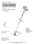
4-CycJe
WEEDWACKER®
GAS TRIMMER
Model No. 316.791970
INCREDI.PULL
TM
RNGEL/EVABLS
with
STARTING
E A S E
MAXFIRE@IGNITION
_
CAUTION:
Before using
this product, read this
manual and follow
all
safety rules and operating
instructions.
Sears, Roebuck
,,,SAFETY
* ASSEMBLY
o OPERATION
" MAINTENANCE
PARTS LIST
ESPANOL, R E1
and Co., Hoffman
Visit our website:
Estates,
www.sears.corn/craftsman
769-03546A
IL 60179, U.S.A.
TABLE
OFCONTENTS
Rules
forSafeOperation
..........................
2
Warranty
Statement
..............................
4
Assembly
Instructions
............................
5
KnowYourUnit.................................
5
OilandFuelInformation
...........................
6
Starting/Stopping
Instructions
......................
7
Operating
Instructions
............................
8
Maintenance
andRepair
Instructions
................
9
Cleaning
andStorage...........................
13
Troubleshooting
Chart...........................
14
Specifications
.................................
14
PartsList....................................
E17
Service
Numbers........................
Backcover
SPARK
ARRESTOR
NOTE
NOTE:
Forusers on U.S. Forest Land and in the states of
California, Maine, Oregon and Washington. All U.S. Forest Land
and the state of California (Public Resources Codes 4442 and
4443), Oregon and Washington require, by law that certain internal
combustion engines operated on forest brush and/or grasscovered areas be equipped with a spark arrestor, maintained in
effective working order, or the engine be constructed, equipped
and maintained for the prevention of fire. Check with your state or
local authorities for regulations pertaining to these requirements.
Failure to follow these requirements could subject you to liability or
a fine. This unit is factory equipped with a spark arrestor. If it
requires replacement, ask a Sears or other qualified service dealer
to install the Accessory Part #753=05297 Spark Arrestor Kit.
CALiFORNiA
PROPOSiTiON
The purpose of safety symbols is to attract your attention to possible
dangers. The safety symbols, and their explanations, deserve your
careful attention and understanding. The safety warnings do not by
themselves eliminate any danger. The instructions or warnings they
give are not substitutes for proper accident prevention measures.
SYMBOL
[_
caution. Attention is required in order to avoid serious
personal injury. May be used in conjunction with other
AFETY or ALERT:
symbols
pictographs.Indicates danger, warning or
[,_
in serious injury to yourself or to others. Always follow
the safety precautions to reduce the risk of fire, electric
ANGER:Failure
obey a safety warning will result
shock
and personal to
injury.
result in injury to yourself and others. Always follow the
safety
precautions
to reduce
risk ofwarning
fire, electric
ARNING:
Failure
to obey the
a safety
can
shock and personal injury.
[_
CAUTION:
Failure to obey a safety warning may result
in property damage or personal injury to yourself or to
others. Always follow the safety precautions to reduce
the risk of fire, electric shock and personal injury.
65 WARNING
NOTE:
THE ENGINE EXHAUST FROM THiS PRODUCT CONTAINS
CHEMICALS KNOWN TO THE STATE OF CALIFORNIA TO
CAUSE CANCER, BIRTH DEFECTS OR OTHER
REPRODUCTIVE HARM.
• iMPORTANT
READ ALL iNSTRUCTiONS
MEANING
Advises you of information or instructions vital to the
operation or maintenance of the equipment.
Read the Operator's Manual and follow all warnings and safety
instructions. Failure to do so can result in serious injury to the
operator and/or bystanders.
FOR QUESTIONS,
CALL
1=800=659=5917
SAFETY INSTRUCTIONS
BEFORE OPERATING
WARNING:
When using the unit, you must follow the
safety rules. Please read these instructions before
operating the unit in order to ensure the safety of the
operator and any bystanders. Please keep these
instructions for later use.
• Read the instructions carefully. Be familiar with the controls and
proper use of the unit.
Do not operate this unit when tired, ill, or under the influence of
alcohol, drugs, or medication.
Children and teens under the age of 15 must not use the unit,
except for teens guided by an adult.
All guards and safety attachments must be installed properly
before operating the unit.
Inspect the unit before use. Replace damaged parts. Check for
fuel leaks. Make sure all fasteners are in place and secure.
Replace parts that are cracked, chipped, or damaged in any way.
Do not operate the unit with loose or damaged parts.
Carefully inspect the area before starting the unit. Remove all
debris and hard or sharp objects such as glass, wire, etc.
Be aware of risk of injury to the head, hands and feet.
Clear the area to be cut before each use. Remove rocks, broken
glass, nails, wire, string and other objects which may be thrown or
become entangled in the cutting attachment. Clear the area of
children, bystanders and pets; keep them outside a 50-foot (15 m)
radius, at a minimum. Even then, they are still at risk from thrown
objects. Encourage bystanders to wear eye protection. If you are
approached, stop the unit immediately.
Use only Hassle-Free TM XRTA QUIET Spiral Line. Never use
metal-reinforced line, wire or rope. These can break off and
become dangerous projectiles.
Squeeze the throttle control and check that it returns
automatically to the idle position. Make all adjustments or repairs
before using unit.
FUEL SAFETY WARNINGS FOR GAS UNITS
[_
vapors can explode if ignited. Take the following
ARNING: Gasoline is highly flammable, and its
precautions:
Store fuel only in containers specifically designed and approved
for the storage of such materials.
Always stop the engine and allow it to cool before filling the fuel
tank. Never remove the fuel tank cap or add fuel when the engine
is hot. Never operate the unit without the fuel cap securely in
place. Loosen the fuel tank cap slowly to relieve any pressure in
the tank.
Add fuel in a clean, well-ventilated outdoor area where there are
no sparks or flames. Remove the fuel cap slowly, and only after
the engine stops. Do not smoke while fueling. Wipe up any spilled
fuel from the unit immediately.
Avoid creating a source of ignition for spilled fuel. Do not start the
engine until fuel vapors dissipate.
Move the unit at least 30 feet (9.1 m) from the fueling source and
site before starting the engine. Do not smoke. Keep sparks and
open flames away from the area while adding fuel or operating
the unit.
WHILE
OPERATING
• Never
startorruntheunitinsideaclosedroomorbuilding.
Breathing
exhaust
fumescanbefatal.Operate
thisunitonlyina
well-ventilated
outdoor
area.
Wear
safety
glasses
orgoggles
thatmeet
ANSI
Z87.1-1989
standards
andaremarked
assuch.
Wear
ear/hearing
protection
whenoperating
thisunit.Wear
afaceordustmaskiftheoperation
isdusty.
Wearheavy
longpants,boots,glovesanda longsleeve
shirt.Do
notwearlooseclothing,
jewelry,
shortpants,sandals
orgo
barefoot.
Secure
hairaboveshoulder
level.
Thecuttingattachment
shield
mustalways
beinplacewhile
operating
theunitasatrimmer.
Donotoperate
unitwithout
both
trimming
linesextended,
andtheproperlineinstalled.
Donot
extend
thetrimming
linebeyond
thelengthoftheshield.
Thisunithasaclutch.
Thecutting
attachment
remains
stationary
whentheengine
isidling.
Ifitdoesnot,taketheunittoaSears
or
otherqualified
service
dealer
foranadjustment.
Adjust
theD-handle
toyoursizeinorder
toprovide
thebestgrip.
Besurethecuttingattachment
isnotincontactwithanything
beforestarting
theunit.
Usetheunitonlyindaylight
orgoodartificial
light.
Avoid
accidental
starting.
Beinthestarting
position
whenever
pulling
thestarter
rope.
Theoperator
andunitmustbeinastable
position
whilestarting.
Refer
toStarting/Stopping Instructions.
Use the right tool. Only use this tool for its intended purpose.
Do not overreach. Always keep proper footing and balance.
Always hold the unit with both hands when operating. Keep a
firm grip on both handles or grips.
Keep hands, face, and feet at a distance from all moving parts. Do not
touch or try to stop the cutting attachment when it rotates.
Do not touch the engine, gear housing or muffler. These parts get
extremely hot from operation, even after the unit is turned off.
Do not operate the engine faster than the speed needed to cut, trim
or edge. Do not run the engine at high speed when not cutting.
Always stop the engine when cutting is delayed or when walking
from one cutting location to another.
If you strike or become entangled with a foreign object, stop the engine
immediately and check for damage. Do not operate before repairing
damage. Do not operate the unit with loose or damaged parts.
Stop the unit, switch the engine to off, and disconnect the spark
plug for maintenance or repair.
Use only replacement parts or accessories recommended for this
tool that are distributed by Sears or a Craftsman outlet. Use of any
replacement parts or accessories purchased elsewhere may be
hazardous, and will also void your warranty.
Keep unit clean of vegetation and other materials. They may
become lodged between the cutting attachment and shield.
To reduce fire hazard, replace a faulty muffler and spark arrestor.
Keep the engine and muffler free from grass, leaves, excessive
grease or carbon build up.
OTHER SAFETY WARNINGS
Never store the unit with fuel in the tank, inside a building where
fumes may reach an open flame (pilot lights, etc.) or sparks
(switches, electrical motors, etc.).
Allow the engine to cool before storing or transporting. Be sure to
secure the unit while transporting.
Store the unit in a dry area, locked up or up high to prevent
unauthorized use or damage, out of the reach of children.
Never douse or squirt the unit with water or any other liquid. Keep
handles dry, clean and free from debris. Clean after each use, see
Cleaning and Storage Instructions.
Keep these instructions. Refer to them often and use them to
instruct other users. If you loan someone this unit, also loan them
these instructions.
SAVE THESE INSTRUCTIONS
• SAFETY AND iNTERNATiONAL
SYMBOLS
•
This operator's manual describes safety and international symbols and pictographs that may appear on this product.
manual for complete safety, assembly, operating and maintenance and repair information.
SYMBOL
MEANING
SYMBOL
'SAFETY ALEftT SYM BOL
Indicates danger, warning or caution. May be used in
conjunction with 0!her symbols or pictographs,
_,_
I
Read the operator's
MEANING
/ START
/ RUN
• ON
ON/OFF
STOP
CONTROL
• ON/OFF STOP CONTROL
, REAl) 0PERATOR'S MANUAL
WARNING:
Read the operator s manual(s) and follow
all warnings and safety instructions. Failure to do so can
result in serious injury to the operator and!or bystanders,
IllLLJl|
OFF or STOP
A
Lt_1_
and pets. at least 50 feet (15 m; from the operating area.
* WEAR EYE AND NEARING PROTECTION
WARNING:
ThrOwn objectS and loud noise Can
cause severe eye injury and hearing loss. Wear eye
protection meeting ANSI Z87:1-1989 standards and ear
protection when operating this unit. Use a full face shield
when needed.
• NOT SURFACE
WARNING:
Do not touch a hot muffler, gear housing
or cylinder. You may get burned. These parts get
extremely hot from operation. They remain hot for a
short time after the unit is turned off.
o THROWN OBJECTS AND ROTATING CUTTER CAN
CAUSE SEVERE iNJURY
r_'_
,, UNLEADED FUEL
II_I1_ !1
AlwaYs uSe Clean freSh unleaded fuel
WARNING:
Do not operate without the cutting
attachment shield in place. Keeo awayfrom the
rotating cutting attachment.
OIL
t
Refer to operator!s
• KEEP BYSTANDERS AWAY
WARNING:
Keep all bystanders, especially children
manual foi the proper type of oil.
.._,jpr
* SHARP BLADE
WARNING:
Sharp blade on cutting attachment
shield. To prevent serious injury, do not touch the line
cutting blade.
CRAFTSMAN
FULLWARRANTY
IfthisCraftsman
product
failsduetoa defectinmaterial
orworkmanship
withintwoyearsfromthedateofpurchase,
return
ittoanySears
store,
PartsandRepair
Service
Center,
orotherCraftsman
outletintheUnited
States
forfreerepair
(orreplacement
ifrepairproves
impossible).
Thiswarranty
applies
foronly90daysifthisproduct
iseverusedforcommercial
orrentalpurposes.
ThiswarrantycoversONLYdefectsin materal
andworkmanship.
Searswill NOTpayfor:
• Expendable
itemsthatcanwearoutfromnormal
usewithinthewarranty
period,
suchascuttingline,filtersorsparkplugs.
Repairs
necessary
because
ofaccident
orfailuretooperate
ormaintain
theproduct
according
toallsupplied
instructions.
Preventive
maintenance,
orrepairs
necessary
duetoimproper
fuelmixture,
contaminated
orstalefuel.
Thiswarranty
givesyouspecific
legalrights,andyoumayalsohaveotherrightswhichvaryfromstatetostate.
Sears,Roebuck
andCo.,Hoffman
Estates,
IL60179
RepairProtection Agreements
Congratulations on making a smart purchase. Your new Craftsman® product is designed and manufactured for years of dependable
operation. But like all products, it may require repair from time to time. That's when having a Repair Protection Agreement can save you
money and aggravation.
Here's what the Repair Protection Agreement* includes:
[]
Expert service by our 10,000 professional repair specialists
[]
Unlimited service and no charge for parts and labor on all covered repairs
[]
Product replacement up to $1500 if your covered product can't be fixed
[]
Discount of t0% from regular price of service and related installed parts not covered by the agreement; also, 10% off regular price of
preventive maintenance check
[]
Fast help by phone - we call it Rapid Resolution - phone support from a Sears representative. Think of us as a "talking owner's manual."
Once you purchase the Repair Protection Agreement, a simple phone call is all that it takes for you to schedule service. You can call anytime
day or night, or schedule a service appointment online.
The Repair Protection Agreement is a risk-free purchase. If you cancel for any reason during the product warranty period, we will provide a
full refund. Or, a prorated refund any time after the product warranty period expires. Purchase your Repair Protection Agreement today!
Some limitations and exclusions apply. For prices and additional information in the U.S.A. call t-800-827=6655.
*Coverage in Canada varies on some items. For full details call Sears Canada at 1=800=361=6665.
Sears Installation Service
For Sears professional installation of home appliances, garage door openers, water heaters, and other major home items, in the U.S.A. or
Canada call f=800-4-MY=HOME ®.
OilFillPlug
Muffler
Spark
Plug
Starter Rope
Grip
Shaft Grip
D-Handle
On/Off Stop
Control
_l Cap
Cold Weather
Start Lever
Craftsman®
Convertible TM Coupler
Throttle
Control
Line
Cutting
Blade
Shaft
Housing
Air Filter Cover
Primer Bulb
Trimmer
Attachment
\
Cutting Attachment
Shield
Hassle-Free
TM
Plus
iNSTALL MNE TRIMMER
UNTIL THE D-HANDLE HAS BEEN ROTATED INTO
ARNING: POSITION
DO NOT ATTEMPT
TO USE THIS UNIT
OPERATING
(Fig. 1).
!_
ADJUSTING
1.
THE D-HANDLE
NOTE:
1.
Turn knob counterclockwise
to
loosen coupler (Fig. 16, p. 9).
2.
While firmly holding attachment,
push it straight into the coupler
until the release button snaps into
the primary hole (Fig. 17, p. 9).
Loosen the screws on the D-handle (Fig. 1).
On/Off Stop Control
Shaft
Housing
(4) Screws
NOTE:
Shaft Grip
Minimum 6
(15.24 crn)
3.
Aligning the release button with
the guide recess (Fig. 17, p. 9)
will help installation.
Turn the knob clockwise to tighten.
LiNE TRIMMER
D-Handle_
Bottom
Clamp
Fig. t
2.
While holding the unit in the operating position (Fig. 2), position
the D-handle to the location that provides you the best grip.
3.
Tighten the clamp screws evenly, until the D-handle is secure.
ATTACHMENT
To make installation easier,
place the unit on the ground or
on a workbench.
APPMCATIONS
Cutting grass and light weeds; edging;
and decorative trimming around trees,
fences, etc.
Fig. 2
WARNING:
OVERFILLING OIL CRANKCASE MAY
CAUSE SERIOUS PERSONAL INJURY. Check and
maintain the proper oil level in the crank case; it is
important and cannot be overemphasized. Check the
oil before each use and change it as needed. See
Changing the Oil.
RECOMMENDED OiL TYPE
Using the proper type and weight of oil in the crankcase is
extremely important. Check the oil before each use and change the
oil regularly. Failure to use the correct oil, or using dirty oil, can
cause premature engine wear and failure.
Use a high-quality SAE 30 weight oil of API (American Petroleum
Institute) service class SF, SG, SH.
ADDING OiL TO CRANKCASE: iNiTiAL USE
NOTE: This unit is shipped without oil. In order to avoid damage to
the unit, put oil in the crankcase before you attempt to start
the unit.
Using Blended Fuels
If you choose to use a blended fuel, or its use is unavoidable, follow
recommended precautions:
• Always use fresh unleaded gasoline
Use a gas stabilizer fuel additive
Drain tank and run the engine dry before storing unit
Using Fuel Additives
The use of a gas stabilizer will inhibit corrosion and minimize the
formation of gum deposits. Using a fuel additive can keep fuel from
forming harmful deposits in the carburetor for up to six (6) months.
Add 0.8 oz. (23 ml.) of fuel additive per gallon of fuel according to
the instructions on the fuel additive container. NEVER add fuel
additives directly to the unit's gas tank.
[_
Your unit is supplied with one 3.04
fluid oz. (90 ml.) bottle of SAE 30 SF,
SG, SH oil (Fig. 3).
NOTE:
WARNING:
Save the empty oil bottle. It
can be used to measure the
correct amount during future
oil changes. See Changing the
Oil.
Funnel
Spout
Gasoline is extremely flammable. Ignited
vapors may explode. Always stop the engine and allow
it to cool before filling the fuel tank. Do not smoke while
filling the tank. Keep sparks and open flames at a
distance from the area.
__
FUELING THE UNIT
Fig. 3
Unscrew the top of the bottle of
oil and remove the paper seal
covering the opening. Replace
the top. Next, cut the tip off the
funnel spout (Fig. 3).
Tip unit so that the back of the
engine is facing up in a vertical
position.
1.
!,_
Remove the fuel cap (Fig. 6).
from fuel spray. Never operate the unit without the fuel
capARNING:
securely inRemove
place. fuel cap slowly to avoid injury
O-Ring _
Oil Fill __
Ne,e,\
Remove the oil fill plug from the
crankcase (Fig. 4).
o,
4. Pour the entire bottle of oil into N,,,._.
the oil fill hole (Fig. 5).
_(_7
NOTE: Never add oil to the fuel or
fuel tank.
3,
outdoor area. Wipe up any spilled fuel immediately.
Avoid
creating Add
a source
of aignition
for spilt
fuel. Do not
ARNING:
fuel in
clean, well
ventilated
start the engine until fuel vapors dissipate.
Fig. 4
Wipe up any oil that may have
spilled and reinstall the oil fill
plug.
Check oil before each use and
change as needed. Refer to
Fig. 5
Checking the Oil Level.
RECOMMENDED
FUEL TYPE
Old fuel is the primary reason for improper unit performance. Be
sure to use fresh, clean, unleaded gasoline. Dispose of the old
gasoline in accordance to Federal, State and Local regulations.
Gas Can Spout f
Fuel Tank
5.
NOTE: This is a four cycle engine. In order to avoid damage to the
unit, do not mix oil with gasoline.
Definition of Blended Fuels
Today's fuels are often a blend of gasoline and oxygenates such as
ethanol, methanol or MTBE (ether). Alcohol-blended fuel absorbs
water. As little as 1% water in the fuel can form acids when stored.
Use fresh fuel (less than 60 days old), when using alcohol-blended fuel.
Fuel Cap
Fig. 6
2.
Place the gas container's
(Fig. 5) and fill the tank.
spout into the fill hole on the fuel tank
NOTE: Do not overfill the tank.
3.
Wipe up any gasoline that may have spilled.
4.
Reinstall the fuel cap.
5.
Move the unit at least 30 ft. (9.1 m) from the fueling source and
site before starting the engine.
[_
ventilated outdoor area. Carbon monoxide exhaust
ARNING:
Operate
unit only
in a wellfumes
can be lethal
in athis
confined
area.
[_
are in the starting position when pulling the starter rope
(Fig. 8). To avoid serious injury, the operator and unit
ARNING:
Avoidposition
accidental
must
be in a stable
whilestarting.
starting.Make sure you
Cold Weather
Start Lever
Primer Bulb
STARTING iNSTRUCTiONS
1.
Check the oil level in the crankcase.
the Oil Level.
Refer to Checking
2.
Fill the fuel tank with fresh, clean unleaded gasoline.
Refer to Fueling the Unit.
NOTE: There is no need to turn the unit on. The On/Off
Stop Control is in the ON ( I ) position at all times.
Fully press and release the primer bulb 10 times,
slowly. Some amount of fuel should be visible in the
primer bulb and fuel lines (Fig. 7). If you can't see fuel
in the bulb, press and release the bulb as many times
as it takes before you can see fuel in it.
IF UNiT IS BELOW 40°F... Push the Cold Weather Start Lever
(Fig. 7) down to the start/closed position and continue to
step 4. DO NOT push this lever down if the unit temperature
is above 40°F.
Fig. 7
3.
4.
With the unit in the starting position (Fig. 8), do not
squeeze the throttle control. Pull the starter rope out a
short distance, until you feel some resistance. This is
usually around 2-4 inches. Pull the starter rope out with
a controlled and steady motion. Repeat this 5 times.
The engine should start.
X
Incredi-Pull /
Starter Rope
ii
5.
If engine starts, squeeze the throttle control to warm
up the engine for 15 to 30 seconds. In cold weather, let
the engine warm up for 30 to 60 seconds.
Throttle
IF ENGINE STARTS AND WEATHER iS COLD... (below
40°F), lift the Cold Weather Start Lever back up to the
run/open position.
IF... the engine does not start, go back to step 3.
Control
Fig. 8
..............
IF... the engine stops while you are squeezing the throttle,
go back to step 4.
WARM RESTART... Once the engine is warm, just pull the
starter rope to restart. Do not squeeze the throttle
control while pulling the starter rope.
NOTE:
The unit uses the Incredi-Pull TM starting system
with MAX FIRE IGNITION TM , which significantly
reduces the effort required to start the engine. You
must pull the starter rope out far enough to hear
the engine attempt to start. There is no need to
pull the rope briskly-- there is no harsh resistance
when pulling. Be aware that this starting method is
vastly different from (and much easier than) what
you may be used to.
STOPPING INSTRUCTIONS
1.
Release your hand from the throttle control. Allow the engine
to cool down by idling.
2.
Press and hold On/Off Stop Control in the OFF (O) position
until engine comes to a complete stop (Fig. 9).
Stop/Off
Throttle
(0)
Start/On
Control
Fig. 9
(I)
l_1
Craftsman Convertible
Coupler
body protection to reduce the risk of injury when
ARNING:
Always wear eye, hearing, foot and
operating
this unit.
HOLDING THE TRIMMER
Before operating the unit, stand in the
operating position (Fig. 10). Check for
the following:
• The operator is wearing eye
protection and proper clothing
With a slightly-bent right arm, the
operator's right hand is holding the
shaft grip
The operator's left arm is straight, the left
hand holding the assist handle
The unit is at waist level
The cutting attachment is parallel to the
ground and easily contacts the grass
without the need to bend over
TIPS FOR BEST TRIMMING
3.
_u_
_
:
4.
Before you begin using any attachment,
read and understand the manual that came with the
attachment. Follow all safety information contained
within.
You can convert this unit to edge grass.
1. Make sure the unit is turned
completely off.
2. Turn the knob counterclockwise
to
loosen coupler (Fig. 16).
Release Button
Fig. 17
WARNING:
To avoid
serious personal injury and
damage to the unit, shut
the unit off before
removing or installing
attachments.
Primary Hole
Guide Recess
RESULTS
Fig. 10
= For best trimming results, operate
unit with throttle control fully squeezed.
Keep the cutting attachment parallel to the ground.
Do not force the cutting attachment. Allow the tip of the line to do the
cutting, especially along walls. Cutting with more than the tip will
reduce cutting efficiency and may overload the engine.
Cut grass over 8 inches (200 mm) by working from top to bottom in
small increments to avoid premature line wear or engine drag.
Cutting from right to left improves the unit's cutting efficiency.
Clippings are thrown away from the operator.
Slowly move the trimmer into and out of the cutting area at the
desired height. Move either in a forward-backward or side-to-side
motion. Cutting shorter lengths produces the best results.
Trim only when grass and weeds are dry.
The life of your cutting line is dependent upon:
- proper adherence of explained trimming techniques
- what vegetation is cut, and
- where vegetation is cut.
For example, the line will wear faster
\\
when trimming against a foundation
_,
wall as opposed to trimming around a
,_-_-"-_
__
tree.
_
_'_
___
DECORATIVE TRiMMiNG
3°_ _
"_
Decorative trimming is accomplished
, __
by removing all vegetation around
_
........ _ __:#-_
trees, posts, fences and more.
_
Rotate the whole unit so that the
cutting attachment is at a 30 ° angle
Fig. 15
to the ground (Fig. 15).
USING THE CRAFTSMAN CONVERTIBLE TM FEATURE
WARNING:
TM
90 ° Edging Hole
(Trimmer Onl
Knob
Fig. 16
Push in the release button (Fig. 17)
and twist the shaft 90 ° until the
release button snaps into the 90 °
hole (Fig. 16).
Turn the knob clockwise to lock the
coupler (Fig. 18).
Upper
Boom
Attachment
Knob
Fig. 18
CRAFTSMAN
CONVERTIBLE
TM
FEATURE
CAUTION:
These attachments are to be snapped into
the primary hole only. Using the wrong hole could lead to
personal injury or damage to the unit.
The coupler allows you to convert this unit for use with the following
attachments:
Cultivator
Blade Edger
Blower
Brush Cutter
Pruner
To install Attachments
CAUTION:
Before operating this unit, be sure that
the release button is fully snapped into the primary
hole (Fig. 16), and that the knob (Fig. 17) is securely
tightened.
NOTE:
1.
2.
3.
4.
To
1.
2.
3.
4.
To make installation easier, place the unit on the ground or
on a workbench.
Make sure the unit is turned completely off.
Turn the knob counterclockwise to loosen the coupler (Fig. 16).
While firmly holding the attachment, push it straight into the
coupler until the release button (Fig. 17) snaps into the primary
hole (Fig. 17). The primary hole is on the opposite side of the
coupler from the knob (Fig. 17). Align the release button with
the Guide Recess (Fig. 17) to help installation.
Turn the knob clockwise to tighten.
Remove Attachments
Make sure the unit is turned completely off
Turn the knob counterclockwise to loosen the coupler.
Press and hold the release button (Fig. 17).
While firmly holding the upper shaft boom (Fig. 18), pull the
attachment out of the coupler.
LiNE REPLACEMENT
for Hassle-Free
Head
TM
Trimmim
Line
Plus Cutting
Always use Craftsman HassleFree TM XTRA QUIET Spiral Line.
insertion
Holes
Choose the line size best suited for Positioning
the job at hand. Red colored line is
Tunnel
designed for cutting grass and
small weeds. Black colored line is
designed for cutting larger weeds
and light brush.
Glide Plate
NOTE: Before inserting new line
into the holes in the cutting
head, identify the proper
Fig. 11
holes. Follow directions as
shown on the glide plate.
Do Not attempt to remove
the cutting head from the
unit when replacing line.
NOTE: Do not mix lines. Use 2
black or 2 red only.
1. Remove the old line and line
glide plate from the cutting
head.
2.
4.
Insert both ends d your line
through the insertion holes in
the side d the cutting head (Fig.
11).
5.
Push and/or pull the line so that
the line is snug against the hub
and is fully extended through the
positioning tunnels (Fig. 12).
6.
Correctly installed line will be
the same length on both sides
(Fig. 13).
NOTE: Make sure that when
installing new line, that the
line is as close to even as
possible. Any variation in
lengths may cause the unit
to vibrate excessively. If this
happens, stop the unit and
make sure the line is even.
7.
Fig. 13
Repeat steps 4 thru 6 to install
the second trimmer line.
8.
Correctly installed, the four
lines will all be the same
length (Fig. 14).
Some line breakage will occur from:
Clean entire surface of cutting
head.
• Entanglement with foreign matter
Normal line fatigue
Attempting to cut thick, stalky
weeds
3.
Reinstall line glide plate (Fig. 11).
The glide plate is a keyed item
Fig. 12
and will only fit one way. If it does
not go into the cLr[ting head smoothly, DO NOT force it. Rotate the
glide plate until it slides into the cutting head easily.
NOTE: The glide plate must be installed in the cutting head before
inserting new line.
Forcing the line into objects
such as walls or fence posts
Fig. 14
* MAINTENANCE
SCHEDULE
NOTE:
J_
maintenance or repairs with unit running. Always service
andARNING:
repair a cool
Disconnect
spark
plug
wire to
Tounit.
prevent
serious the
injury,
never
perform
ensure that the unit cannot start.
Maintenance, replacement, or repair of the emission control
devices and system may be performed by a Sears or other
qualified service dealer.
In order to assure peak performance of your engine, inspection of
the engine exhaust port may be necessary after 50 hours of
operation. If you notice lost RPM, poor performance or general lack
of acceleration, this service may be required. If you feel your engine
is in need of this inspection, refer service to a Sears or other qualified
service dealer for repair. DO NOT attempt to perform this process
yourself as engine damage may result from contaminants involved in
the cleaning process for the port.
Perform these required maintenance procedures at the frequency
stated in the table. These procedures should also be a part of any
seasonal tune-up.
NOTE:
=
Some maintenance procedures may require special tools or
skills. If you are unsure about these procedures take your unit
to a Sears or other qualified service dealer.
FREQUENCY
MAINTENANCE
REQUIRED
SEE
Before starting engine
Fill fuel tank with fresh fuel
Check oil
p. 6
p. 10
Every 10 hours
Clean and re-oil air filter
p. 11
1st change at 10 hours
At 25 hours/every 25 hours
Every 50 hours
Change oil
Change oil
Clean spark arrestor
p. 10
p. 10
p. 13
10 hours on new engine
Every 25 hours
Check rocker arm to valve clearance and adjust
Check rocker arm to valve clearance and adjust
p. 12
p. 12
Every 25 hours
Check spark plug condition and gap
p. 13
g
CHECKING
THE OiL LEVEL
CHANGING
The importance of checking and maintaining the proper oil level in
the crankcase cannot be overemphasized. Check oil before each
use:
1.
2.
_
Stop the engine and allow oil to drain into the crankcase.
Place the engine on an elevated, level surface with the cutting
head shield hanging off the surface to get an accurate oil level
reading (Fig. 19).
handling
unit. Wear gloves to prevent injury when
ARNING:
For a new engine, change the oil after the first 10 hours of
operation. Change the oil while the engine is still warm. The oil will
flow freely and carry away more impurities.
1.
Unplug spark plug boot to prevent accidental starting.
2.
Remove the oil fill plug.
3.
Pour the oil out of the oil fill
hole and into a container by
tipping the unit to a vertical
position (Fig. 22). Allow
ample time for complete
drainage.
4.
Wipe up any oil residue on
the unit and clean up any oil
that may have spilled.
Dispose of the oil according
to Federal, State and local
regulations.
Refill the crankcase with
3.04 fluid ounce (90 ml) of
SAE 30 SF, SG, SH oil.
(
Fig. 19
3.
Keep dirt, grass clippings and other debris out of the engine.
Clean the area around the dipstick before removing it.
4. Remove the oil fill plug.
5. Look into the oil fill hole, use a flashlight if needed. The oil
should be just touching the innermost thread (Fig. 19).
6. If the oil level is not touching the innermost thread on the oil fill
hole, add a small amount of oil to the oil fill hole and recheck
(Fig. 20). Repeat this procedure until the oil level reaches the
innermost thread on the oil fill hole.
NOTE: Do not overfill the unit.
NOTE:
THE OiL
5.
Make sure the O-ring is in place on the oil fill plug when
checking and changing the oil (Fig. 21).
O-Ring
'2 Ma,O,ri' L
l inJ/
Fig.20 _
Fig. 22
NOTE: Use the bottle and spout saved from initial use to measure
the correct amount of oil. The top of the label on the bottle
measures approximately 3.04 ounces (90 ml) (Fig. 23).
Check the level; See Checking the Oil Level. If the level is
low, add a small amount of oil and recheck. Do not overfill
(Fig. 23).
o, ri,
Fig.21
\
Fig. 23
t0
6.
Replace the oil fill plug.
7.
Reconnect the spark plug boot.
AiRFILTER
MAINTENANCE
i_
NOTE: If the unit is
operated without
the air filter, you
will VOiD the
warranty.
turn the unit off and allow it to cool before you clean or
WARNING:
To avoid serious personal injury, always
service it.
7.
Cleaning the Air Filter
Clean and re-oil the air filter every 10 hours of operation. It is an
important item to maintain. Failure to maintain your air filter properly
can result in poor performance or can cause permanent damage to
your engine.
1.
Open the air filter cover. Push the tab on the under side of the
cover inward. Then pull the air filter cover out and up. (Fig. 24).
8.
Reinstall the air filter
cover. Position the
slots on the top of the
air filter cover onto the
tabs at the top of the
back plate (Fig. 28).
Tabs
Back Plate
Air
Locking Tab
Swing the cover down
Fig. 28
until the tab on the air
filter backplate snaps into place in the slot on the air filter cover
(Fig. 29).
Air Filter Cover
0
Tab
Fig. 24
2.
3.
Remove the air filter (Fig. 23).
Wash the filter in detergent and
water (Fig. 25). Rinse the filter
thoroughly and allow it to dry.
_
/
4.
Apply enough clean SAE 30 motor
oil to lightly coat the filter (Fig. 26).
[ _l
5.
Squeeze the filter to spread and
remove excess oil (Fig. 27).
6.
Replace the filter (Fig. 24).
iDLE SPEED ADJUSTMENT
The idle speed of the engine is
adjustable. An idle adjustment
screw is between the air filter
cover and the engine starter
housing (Fig. 30).
Fig. 29
Fig. 25
sure the cutting attachment has stopped rotating before
WARNING:
To prevent
serious personal injury, make
you turn it off and
set it down.
NOTE: Careless adjustments
can seriously damage
your unit. Aside from
the idle speed, only a
Sears or other qualified
service dealer should
make carburetor
adjustments.
\
Fig. 26
Tab
1. Check Fuel
Old fuel is usually the reason for idle speed problems. Drain and
refill the tank with fresh fuel prior to making any adjustments. Refer
to Oil and Fuel Information.
2. Clean Air Filter
The condition of the air filter is important to the operation of the
unit. A dirty air filter will restrict air flow. This is often mistaken for
an out of adjustment idle. Check the condition of the air filter before
adjusting the idle speed screw. Refer to Air Filter Maintenance.
Fig. 27
tl
3.AdjustIdleSpeedScrew
5. Cleandirtfromaround
therocker
idle speed adjustments. Wear protective clothing and
observe all safety instructions to prevent serious personal
ARNING: The cutting attachment may spin during
injury.
[_
6.
If, after checking the fuel and cleaning the air filter, the engine still
will not idle, adjust the idle speed screw as follows:
1.
Start the engine and let it run at a high idle for a minute to
warm up. Refer to Starting/Stopping
Instructions.
2.
Release the throttle trigger and let the engine idle. If the engine
stops, insert a small phillips screwdriver in between the Air
Filter Cover and the Engine Cover (Fig. 30). Turn the idle speed
screw in, clockwise, 1/8 of a turn at a time (as needed) until the
engine idles smoothly.
NOTE:
3.
The cutting attachment
idles.
arm cover. Remove the screw
holding the rocker arm cover with
a large flat blade screwdriver or
Torx T-25 bit (Fig. 32). Remove
the rocker arm cover and gasket.
Pull the starter rope slowly to
bring the piston to the top of its
travel, (known as top dead
center). Check that:
Rocker
Arm
Cover
\
\
Spark
Plug
Hole
The piston is at the top of its travel.
Look in the spark plug hole to view
the piston (Fig. 33)
Both rocker arms move freely, and
both valves are closed.
Fig. 32
Adjusting
should not rotate when the engine
Rocker Arms
Nuts
INTAKE
If the cutting attachment rotates when the engine idles, turn the
idle speed screw counterclockwise
1/8 of a turn at a time (as
needed), until the attachment stops turning.
Checking the fuel, cleaning the air filter, and adjusting the idle
speed should solve most engine problems. If not and all of the
following are true:
EXHAUST
• the engine will not idle
the engine hesitates or stalls on acceleration
there is a loss of engine power
Have the carburetor adjusted by a Sears or other qualified service
dealer.
Feeler Gauge
Spark Flug
Hole
ROCKER ARM CLEARANCE
This requires disassembly of the engine. If you feel unsure or
unqualified to perform this, take the unit to a Sears or other
qualified service dealer
If these statements
NOTE:
7.
Fig. 33
Inspect the valve to rocker arm clearance with a feeler
gauge after the first 10 hours of operation and every 25
hours of operation.
The engine must be cold when checking or adjusting the valve
clearance.
are not true, repeat step 6.
Slide the feeler gauge between the rocker arm and the top of
each valve stem. Measure the clearance between the valve
stem and rocker arm (Fig. 34). Measure both the intake and
exhaust valves.
Adjusting
This task should be performed inside, in a clean, dust free area.
1. Remove the six (6) screws on the back of the engine cover with
a Flat-head or T-25 Torx screwdriver (Fig. 31).
Rocker Arm
View Of The Rear Engine Cover
Remove
[
[
[
[
I
]
]
] C_DGI
.003-.006 in.
(.076-.152 ram)
Remove
Screws
Feelertauge
Screws
Valve Stem
Fig. 34
The recommended clearance for both intake and exhaust is .003 .006 in. (.076 - 0.152 mm). Use a standard automotive .005 in.
(0.127 mm) feeler gauge. The feeler gauge should slide between the
rocker arm and valve stem with a slight amount of resistance,
without binding. See Figures 33 and 34.
Fig. 31
2.
Disconnect
the spark plug wire.
3.
Clean dirt from around the spark plug. Remove the spark plug
from the cylinder head by turning a 5/8 in. socket
counterclockwise.
4.
Remove the engine cover (Fig. 31).
i2
8. Iftheclearance
isnotwithinspecification:
4. Remove
thesparkarrestor
screen
fromthesparkarrestor
a.Turntheadjusting
nutusinga 5/16inch(8mm)wrench
ornut
diverter.
driver(Fig.34).
5. Clean
thesparkarrestor
screen
withawirebrushorreplace
it.
• Toincrease
clearance,
turntheadjusting
nut
6. Reinstall
thesparkarrestor
screen,
sparkarrestor
diverter
and
counterclockwise,
screws.
CLEANING
Todecrease
clearance,
turntheadjusting
nutclockwise.
b.Recheck
bothclearances,
andadjustasnecessary.
9. Reinstall
therockerarmcoverusinga newgasket.
Torque
the
turn your unit off and allow it to cool before you clean
screwto20-30inolb(2.2-3.4
N,m).
!_IL
I WARNING:
or service it. To avoid serious personal injury, always
10.Check
thesparkplugandreinstall.
SeeReplacing
theSpark
Use a small brush to clean off the outside of the unit. Do not use
Plug.
strong detergents. Household cleaners that contain aromatic oils
11.Replace
thesparkplugwire.
such as pine and lemon, and solvents such as kerosene, can
12.Reinstall
theengine
cover.Checkalignment
ofthecoverbefore damage plastic housing or handle. Wipe off any moisture with a
soft cloth.
tightening
thescrews.
Tighten
screws.
STORAGE
Never store the unit with fuel in the tank where fumes may reach
an open flame or spark.
REPLACING THE SPARK PLUG
[_1
electrodes. Grit in the engine could damage the
ARNING: Do not sand blast, scrape or clean
cylinder.
Allow the engine to cool before storing.
Lock up the unit to prevent unauthorized
Use a replacement part number 753-05255 or Champion spark
plug, #RDZ19H. The correct air gap is 0.025 in. (0.635 ram).
Remove the plug after every 25 hours of operation and check its
condition.
1.
Stop the engine and allow it to cool. Remove the six (6) screws
on the back of the engine cover with a Flat-head or T-25 Torx
screwdriver (Fig. 31).
2.
Grasp the plug wire firmly and
pull the cap from the spark plug.
3.
Clean dirt from around the spark
plug. Remove the spark plug
from the cylinder head by turning
a 5/8 in. (16 mm) socket
counterclockwise.
4.
5.
LONG TERM STORAGE
If the unit must be stored for a long time:
0.025 in.
(0.635 mm)
Replace cracked, fouled or dirty
spark plug. Set the air gap at
0,025 in. (0.635 ram) using a
feeler gauge (Fig. 35).
Fig. 35
Install a correctly-gapped
spark
plug in the cylinder head. Turn the 5/8 in. socket clockwise until
snug.
If using a torque wrench, torque to:
t10-120 in.olb. (12.3-t3.5 N,m)
Do not over tighten.
SPARK ARRESTOR MAINTENANCE
Remove the rear engine cover. See RockerArm
2.
With a flat blade screwdriver or Torx T-20 bit and a T-25 bit,
remove the screws attaching the spark arrestor diverter to the
muffler (Fig. 36).
Spark Arrestor
Clearance,
Screen
Diverter
3,
Drain all gasoline from the gas tank into a container. Do not use
gas that has been stored for more than 60 days. Dispose of the
old gasoline in accordance to Federal, State, and Local
regulations.
2.
Start the engine and allow it to run until it stalls. This ensures
that all gasoline has been drained from the
carburetor.
3.
Allow the engine to cool. Remove the spark plug and put 5
drops of high quality motor oil into the cylinder. Pull the starter
rope slowly to distribute the oil. Reinstall the spark plug.
/
Remove the spark plug and drain all of the oil from the
cylinder before attempting to start the trimmer after
storage.
4.
Change the oil, referring to Changing the Oil. Dispose of the old
oil in accordance to Federal, State and Local regulations.
5.
Thoroughly clean the unit and inspect for any loose or
damaged parts. Repair or replace damaged parts and tighten
loose screws, nuts or bolts. The unit is ready for storage.
TRANSPORTING
Allow the engine to cool before transporting.
Secure the unit while transporting.
Drain the gas tank before transporting.
Tighten gas cap before transporting.
Muffler
so
1.
NOTE:
1.
use or damage.
Store the unit in a dry, well-ventilated area.
Store the unit out of the reach of children.
T-25 Screw
Fig. 36
Pull the the spark arrestor diverter out of the muffler. Remove
the spark arrestor diverter.
t3
CAUSE
Empty
fueltank
ACTION
Fillfueltankwithfuel
Oldfuel
Draingastankandaddfreshfuel
Plugged
sparkarrestor
Cleanorreplace
sparkarrestor
CAUSE
Airfilterisplugged
ACTION
Replace
orcleantheairfilter
Improper
idlespeed
Adjustidlespeed
CAUSE
Oldfuel
ACTION
Draingastankandaddfreshfuel
Cutting
attachment
bound
with grass
Stop the engine and clean the cutting attachment
Plugged spark arrestor
Clean or replace spark arrestor
CAUSE
ACTION
Old fuel
Drain gas tank and add fresh fuel
Fouled spark plug
Replace or clean the spark plug
NOTE:
For repairs beyond the minor adjustments listed above, contact your nearest Sears Parts & Repair center (1-800-4-MY-HOME
other qualified service dealer.
HELP?
You !ol,find Lhe answer
and _ore
_>)or
I
on managemyhOmeotom
o Findthis and aLL},our other productmanuals online.
oGet_n_wers
fro_ourte_mofhome
experts.
oGet_person_tized
m_inten_nce
planforyourhome.
Find information and tools to help with home projects.
f4
oofor free[
Engine Type ............................................................................................................................................................................
Air-Cooled, 4-Cycle
Displacement ..............................................................................................................................................................................
1.8 cu. in. (29 cc)
Operating RPM .....................................................................................................................................................................................
6,800+ rpm
Idle Speed RPM .........................................................................................................................................................................
2,800 - 3,600 rpm
Ignition Type .......................................................................................................................................................
Electronic MAX FIRE IGNITION TM
Ignition Switch ..................................................................................................................................................................................
Rocker Switch
Valve clearance ................................................................................................................................................
0.003-0.006 in. (0.076-0.152 mm)
Spark Plug .........................................................................................................................
Champion Spark Plug #RDZ19H or Similar Spark Plug
Spark Plug Gap ..................................................................................................................................................................
0.025 inch (0.635 mm)
Lubrication ..............................................................................................................................................................................................
SAE 30 Oil
Crankcase Oil Capacity ..................................................................................................................................................................
3.04 oz (90 ml)
Fuel .........................................................................................................................................................................................................
Unleaded
Carburetor .........................................................................................................................................................................
Diaphragm, All-Position
Starter .............................................................................................................................................................
Incredi-Pull TM Starting Auto Rewind
Muffler .......................................................................................................................................................................................
Baffled with Guard
Throttle .................................................................................................................................................................................
Manual Spring Return
Fuel Tank Capacity ...........................................................................................................................................................................
14 oz (414 ml)
Drive Shaft Housing .....................................................................................................................................
Steel Tube (Craftsman Convertible TM)
Throttle Control ...........................................................................................................................................................................
Finger-Tip Trigger
Approximate Unit Weight (No fuel, with Hassle-Free TM Plus, shield & D-handle) ..........................................................
11.5-13.0 Ibs (5.2-5.9 kg)
Cutting Mechanism .........................................................................................................................................................
Hassle-Free TM Plus Head
Timming Line .............................................................................................................................................
Hassle-Free TM XRTA QUIET Spiral Line
* All specifications are based on the latest product information
time without notice.
CALiFORNiA
available at the time of printing. We reserve the right to make changes at any
/ EPA EMiSSiON
Your Warranty
CONTROL
WARRANTY
STATEMENT
Rights and Obligations
The California Air Resources Board, the Environmental Protection Agency, and Sears Brands LLC (Sears)are pleased to explain the emission control
system warranty on your 2007 and later small off-road engine. In California and the 49 states, new small off-road engines must be designed, built and
equipped to meet the state's stringent anti-smog standards. Sears must warrant the emission control system on your small off-road engine for the periods
of time listed below provided there has been no abuse, neglect or improper maintenance of your small off-road engine.
Your emission control system may include parts such as the carburetor or fuel-injection
Also included may be hoses, belts, connectors and other emission-related assemblies.
Where a warrantable
system, the ignition system, and catalytic
converter.
condition exists, Sears will repair your small off-road engine at no cost to you including diagnosis, parts and labor.
The 2007 and later small off-road engines are warranted for two years. If any emission-related
repaired or replaced by Sears.
part on your engine is defective, the part will be
Owners Warranty Responsibilities
As the small off-road engine owner, you are responsible for the performance of the required maintenance listed in your operator's manual.
Sears recommends that you retain all receipts covering maintenance on your small off-road engine, but Sears cannot deny warranty solely
for the lack of receipts or for your failure to ensure the performance of all scheduled maintenance.
• As the small off-road engine owner, you should however be aware that Sears may deny you warranty coverage if your small off-road
engine or a part has failed due to abuse, neglect, improper maintenance or unapproved modifications.
• You are responsible for presenting your small off-road engine to a Sears Authorized Service Center as soon as a problem exists. The
warranty repairs should be completed in a reasonable amount of time, not to exceed 30 days.
If you have any questions regarding your warranty rights and responsibilities,
you should call 1-800-4-MY-HOME®.
Manufacturer's
Warranty Coverage
• The warranty period begins on the date the engine or equipment is delivered to the retail purchaser.
The manufacturer warrants to the initial owner and each subsequent purchaser, that the engine is free from defects in material and
workmanship which cause the failure of a warranted part for a period of two years.
Repair or replacement of warranted part will be performed at no charge to the owner at an Authorized Sears Service Center. For the
nearest location please contact Sears at: 1-800-4-MY-HOME®.
Any warranted part which is not scheduled for replacement, as required maintenance or which is scheduled for only for regular inspection to the
effect of "Repair or Replace as Necessary" is warranted for the warranty period. Any warranted part which is scheduled for replacement as
required maintenance will be warranted for the period of time up to the first scheduled replacement point for that part.
The owner will not be charged for diagnostic labor which leads to the determination that a warranted part is defective, if the diagnostic
work is performed at an Authorized Sears Service Center.
The manufacturer is liable for damages to other engine components caused by the failure of a warranted part still under warranty.
Failures caused by abuse, neglect or improper maintenance are not covered under warranty.
t5
• Theuseofattachment
ormodified
partscanbegrounds
fordisallowing
awarranty
claim.Themanufacturer
is notliabletocoverfailures
of
warranted
partscaused
bytheuseofattachment
ormodified
parts.
Inordertofileaclaim,gotoyournearest
Authorized
Sears
Service
Center.
Warranty
services
orrepairs
willbeprovided
atallAuthorized
Sears
Service
Centers.
Anymanufacturer
approved
replacement
partmaybeusedintheperformance
ofanywarranty
maintenance
orrepairofemission
related
partsandwillbeprovided
withoutcharge
totheowner.
Anyreplacement
partthatisequivalent
inperformance
ordurability
maybeused
innon-warranty
maintenance
orrepairandwillnotreduce
thewarranty
obligations
ofthemanufacturer.
Emission Warranty Parts List:
The following components are included in the emission-related warranty of the engine: air filter, carburetor, primer, fuel lines, fuel pick up/fuel
filter, ignition module, spark plug, and muffler. Valves and Cam are additionally included if your engine is a 4-Stroke Model.
CALIFORNIA
EVAPORATIVE
EMISSION
CONTROL WARRANTY
STATEMENT
Your Warranty Rights and Obligations
The California Air Resources Board and Sears Brands LLC (Sears) is pleased to explain the evaporative emission control system's warranty
on your 2007 model year and later small off-road (equipment type) engine. In California, new equipment that use small off-engines must be
designed, built, and equipped to meet the State's stringent anti-smog standards Sears must warrant the evaporative emission control
system on your small off-road Lawn & Garden engine for the period listed below provided there has been no abuse, neglect or improper
maintenance of your equipment.
Your evaporative emission control system may include parts such as: carburetors, fuel tanks, fuel lines, fuel caps, valves, canisters, filters,
vapor hoses, clamps, connectors, and other associated components.
For engines less than or equal to 80 cc, only the fuel tank is subject to
the evaporative emission control warranty requirements of this section. The displacement of your small off road engine is less than 80 cc.
Manufacturer's
Warranty Coverage
This evaporative emission control system is warranted for two years. If any evaporative emission-related part on your equipment is defective,
the part will be repaired or replaced by Sears.
Owner's Warranty Responsibilities
As the small off-road Lawn & Garden engine owner, you are responsible for performance of the required maintenance listed in your owner's
manual. Sears recommends that you retain all receipts covering maintenance on your Lawn & Garden Engine but Sears cannot deny warranty
solely for the lack of receipts.
As the small off-road Lawn & Garden engine owner, you should however be aware that the Sears may deny you warranty coverage if your
fuel tank has failed due to abuse, neglect, or improper maintenance or unapproved modifications.
You are responsible for presenting your Lawn & Garden fuel tank to Sears distribution center or service center as soon as the problem
exists. The warranty repairs should be completed in a reasonable amount of time, not to exceed 30 days. If you have a question
regarding your warranty coverage, you should contact Sears at f-800-4-MY-HOME®.
Defects Warranty Requirements
(a) The warranty period begins on the date the engine or equipment is delivered to an ultimate purchaser.
(b) General Evaporative Emissions Warranty Coverage. The fuel tank must be warranted to the ultimate purchaser and any subsequent
owner that the evaporative emission control system when installed was:
(1) Designed, built, and equipped so as to conform with all applicable regulations; and
(2) Free from defects in materials and workmanship that causes the failure of a warranted part for a period of two years.
(c) The warranty on evaporative emissions-related parts will be interpreted as follows:
(1) Any warranted part that is not scheduled for replacement as required maintenance in the written instructions must be warranted for the
warranty period defined in subsection (b)(2). If any such part fails during the period of warranty coverage, it must be repaired or
replaced by Sears. Any such part repaired or replaced under the warranty must be warranted for a time not less than the remaining
warranty period.
(2) Any warranted part that is scheduled only for regular inspection in the written instructions must be warranted for the warranty period
defined in subsection (b)(2). A statement in such written instructions to the effect of "repair or replace as necessary" will not reduce
the period of warranty coverage. Any such part repaired or replaced under warranty must be warranted for a time not less than the
remaining warranty period.
(3) Any warranted part that is scheduled for replacement as required maintenance in the written instructions must be warranted for the
period of time prior to the first scheduled replacement point for that part. If the part fails prior to the first scheduled replacement, the part
must be repaired or replaced by the Sears. Any such part repaired or replaced under warranty must be warranted for a time not less than
the remainder of the period prior to the first scheduled replacement point for the part.
(4) Repair or replacement of any warranted part under the warranty provisions of this article must be performed at no charge to the
owner at a warranty station.
(5) Not withstanding the provisions of subsection (4) above, warranty services or repairs must be provided at distribution centers that
are franchised to service the subject engines or equipment.
(6) The owner must not be charged for diagnostic labor that leads to the determination that a warranted part is in fact defective,
provided that such diagnostic work is performed at a warranty station.
(7) Throughout the evaporative emission control system's warranty period set out in subsection (b)(2), Sears must maintain a supply of
warranted parts sufficient to meet the expected demand for such parts.
(8) Manufacturer approved replacement parts must be used in the performance of any warranty maintenance or repairs and must be
provided without charge to the owner. Such use will not reduce the warranty obligations of the manufacturer issuing the warranty.
(9) The use of any attachment or modified parts will be grounds for disallowing a warranty claim made in accordance with this article.
The manufacturer issuing the warranty will not be liable under this Article to warrant failures of warranted parts caused by the use of
an attachment or modified part.
(10) Sears shall provide any documents that describe the warranty procedures or policies within five working days of request by the Air
Resources Board.
Emission Warranty
(1) Fuel Tank
Written instructions for the maintenance
engine or equipment.
Parts List
and use of the evaporative emissions control system by the owner shall be furnished with each new
t6
ManuaJ deJ Operador
®
4-Ciclos
WEEDWACKER®
A GASOLINA
RECORTADOR
Modelo No. 316.791970
INCREDI.PULL_
M
UNBELIEVABLE
with
STARTING
E A S E
MAX FINE_tclGNITICIN
M
PRECAUCION:
Antes de
utilizar
este producto,
lea
este manual y siga todas
las reglas de seguridad
y
las instrucciones
de
funcionamiento,
Sears, Roebuck
Visite
•' SEGURIDAD
,, MONTAJE
,, OPERACION
,, MANTENIMIENTO
• LISTA DE PARTES
and Co., Hoffman
nuestro
Estates,
IL 60179, U.S.A.
sitio web: www.sears.corn/craftsman
769-03546A
INDICE
DECONTENIDOS
Los simbolos de seguridad se utilizan para Ilamar su atenci6n
Normas
paraunaoperaci6n
segura....................
E2
sobre posibles peligros. Los simbolos de seguridad y sus
Garantfa
..........................................
E4
explicaciones merecen toda su atenci6n y comprensi6n. Los
Conozca
suunidad.................................
E5
dmbolos de seguridad no eliminan ning0n peligro por si mismos.
Instrucciones
deensamble
...........................
E5
Las instrucciones o advertencias que ofrecen no substituyen las
Informaci6n
delaceite
y delcombustible
................
E6
medidas adecuadas de prevenci6n de accidentes.
Instrucciones
dearranque
yapagado..................
E7
Instrucciones
deoperaci6n
...........................
E8 SIMBOLO
SIGNIFICADO
Instrucciones
demantenimiento
yreparaci6n
............ E9
Limpieza
yalmacenamiento
.........................
E13 _L
I ALERTA DE SEGURIDAD
: Indica peligro,
Cuadro
desoluci6n
deproblemas
....................
E14
I advertencia o precauci6n. Debe prestar atenci6n para
Especificaciones
..................................
E14
I evitar sufrir graves lesiones personales. Puede ser
ListadePiezas
...................................
E17
.[ utilizado junto con otros dmbolos o figuras.
NL_meros
deServicio......................
Contraportada
PELIGRO : El no obedecer una advertencia de
PARACHISPAS
seguridad puede conducir a que usted u otras personas
NOTA:Para los usuarios en tierras forestales de los EE.UU. yen
los estados de California, Maine, Oregon y Washington. Todos
los terrenos forestales de los EE.UU. y el estado de California
(C6ctigos de Recursos Publicos 4442 y 4443), Oregon y Washington,
requ_eren por decreto, que ciertos motores de combusti6n interna
que se hagan funcionar en zonas boscosas y/o zonas cubiertas pot
pastizales, esten equipados con un parachispas, que sean
mantenidos en buen estado de funcionamiento o que el motor sea
construido, este equipado y sea mantenido para evitar incendios.
Consulte los reglamentos pertinentes a esos requisitos con las
autoridades estatales o locales. El incumplimiento de esos requisitos
i_uede responsabilizarle o someterle a la imposici6n de una multa.
sta unidad fue equipada en la fAbrica con un parachispas. Si
requiere sustituci6n, hay una Pantalla Parachispas disponible,
Pieza # 753=05297 al contactar el departamento de servicio.
CALiFORNiA
PROPOSiTiON
sufran graves lesiones. Siga siempre las precauciones de
seguridad para reducir el riesgo de incendio, descarga
electrica y lesiones personales.
ADVERTENCIA
: El no seguir una advertencia de
seguridad puede conducir a que usted u otras personas
sufran lesiones. Siga siempre las precauciones de
seguridad para reducir el riesgo de incendio, descarga
electrica y lesiones personales.
PRECAUCION
: El no seguir una advertencia de
seguridad puede conducir a dafio patrimonial o a que usted
u otras personas sufran lesiones personales. Siga siempre
las precauciones de seguridad para reducir el riesgo de
incendio, descarga electrica y lesiones personales.
65 WARNING
REMARQUE: Le ofrece informaci6n o instrucciones que son
esenciales para la operaci6n o mantenimiento del equipo.
Lea eJ manual deJ operador y siga todas Jas advertencias
e
instrucciones de seguridad. De no hacerlo, el operador y/o los
espectadores
pueden sufrir graves lesiones.
LAS EMISIONES DEL MOTOR DE ESTE PRODUCTO
CONTIENEN SUBSTANCIAS QUIMICAS QUE EL ESTADO DE
CALiFORNiA CONOCE COMO CAUSANTES DECANCER,
DEFECTOS DE NACIMIENTO U OTROS DAI_IOS
REPRODUCTIVOS.
• IMPORTANTE
LEA TODAS LAS INSTRUCCIONES
Sl TIENE
PREGUNTAS,
LLAME
AL
1-800-859-5917
JNFORMACJON DE SEGURJDAD
ANTES DE LA OPERACION
Use s61o Hassle-Free TM XTRA QUIET linea espiral. Nunca use linea
reforzada con metal, alambre o soga. Se pueden romper y convertirse
en proyectiles peligrosos.
Optima el control del estrangulador y compruebe que regresa
automaticamente a la posici6n de marcha en vacio. Haga todos los
ajustes o reparaciones antes de usar la unidad.
ADVERTENCIAS DE SEGURIDAD PARA LOS RECORTADORES
A GASOLINA
ADVERTENCIA:
AI utilizar la unidad, debe observar
las reglas de seguridad. Lea estas instrucciones antes
de operar la unidad a fin de garantizar la seguridad del
operador y cualquier transeL_nte. Guarde estas
instrucciones para uso posterior.
• Lea las instrucciones cuidadosamente. Familiarfcese con los controles
y el uso adecuado de la unidad.
No opere esta unidad cuando este cansado, enfermo o bajo la
influencia de alcohol, drogas o medicamentos.
Los nifios y los adolescentes menores de 15 a_os de edad no deben
usar la unidad. Los adolescentes pueden hacerlo bajo la supervisi6n
de un adulto.
Todos los dispositivos de protecci6n y los accesorios de seguridad
deben estar instalados adecuadamente antes de operar la unidad.
Inspeccione la unidad antes de usarla. Reemplace las piezas
dafiadas. Verifique si hay fugas de combustible. Asegurese de que
todos los fi adores esten en su lugar y asegurados. Reemplace las
p ezas que esten agr etadas, ast Iladas o daSadas en cua qu er forma.
No opere la unidad con piezas sueltas o dahadas.
Inspeccione cuidadosamente el Area antes de operar la unidad.
Elimine todos los escombros y los objetos duros o filosos tales como
cristal, alambre, etc.
Este consciente del riesgo de lesi6n en la cabeza, las manos y los pies.
No permita nir]os, espectadores ni mascotas en el Area. Los nir]os, los
espectadores y las mascotas deben estar fuera de un radio de 50 pies
(15 m.) como minimo; de todas formas los espectadores correran el
riesgo de set golpeados por objetos lanzados pot la unidad. Se debe
exhortar a los espectadores a que usen protecci6n para los ojos. Si se
le acerca alguien apague la unidad de inmediato.
J_
sus gases pueden explotar si se encienden. Tome las
ADVERTENCIA:
La gasolina es muy inflamable y
siguientes precauciones:
Guarde el combustible en envases que hayan sido diser_ados y
aprobados para el almacenamiento de dichos materiales.
Antes de Ilenar el tanque de combustible, apague siempre el
motor y espere que se enfrfe. No retire nunca la tapa del tanque
de combustible ni cargue combustible mientras el motor este
caliente. No opere nunca la unidad sin la tapa del combustible
colocada firmemente en su lugar. Aflo e la tapa del combustible
lentamente para disipar la presi6n del tanque.
Cargue el combustible en un area exterior bien ventilada donde
no haya chispas ni llamas. Quite lentamente la tapa del
combustible s61o despues de apagar el motor. No fume mientras
carga el combustible. Limpie de inmediato todo el combustible
que se haya derramado.
Evite crear una fuente de encendido pot combustible derramado.
No arranque el motor hasta que se hayan disipado los vapores
del combustible.
Aleje la unidad a pot Io menos 9,1 m (30 pies), del lugar de carga
de combustible antes de arrancar el motor. No fume, mantenga
las chispas y las llamas abiertas lejos del Area mientras carga el
combustible u opera la unidad.
E2
DURANTE
LAOPERACION
No opere el motor a una velocidad mayor que la necesaria para
cortar, recortar o recortar los bordes. No haga funcionar el motor
a alta velocidad mientras no esta cortando.
Apague siempre el motor cuando demore el corte o mientras
camlna entre zonas de corte.
Si golpea o se enreda con algun objeto extra,o, apague el motor
de inmediato y verifique si hay dahos. Repare todos los dahos
antes de volver a intentar operar la unidad. No opere la unidad si
tiene piezas flojas o dahadas.
Apague el motor para realizar todo el mantenimiento, reparaciones
o cambio del accesorio de corte u otros accesorios.
Utilice solamente piezas o accesorios de reemplazo recomendados
para esta herramienta que sean distribuidos pot Sears o per un
establecimiento comercial de Craftsman. El use de cualquier pieza
de reemplazo o accesorio adquirido en cualquier otto lugar puede
resultar peligroso, y tambien anulara su garantia.
Mantenga la unidad libre de vegetaci6n y otros materiales.
Pueden alojarse entre el accesorio de corte y la protecci6n.
Para reducir el riesgo de incendio, cambie los silenciadores y amortiguadores de chispas defectuosos, mantenga el motor y el stlenciador
libre de paste, hojas, grasa excesiva o acumulaciones de carbono.
OTRAS ADVERTENCIAS DE SEGURIDAD
• Nunca guarde la unidad con combustible en el tanque, dentro de un
edificio donde las emanaciones puedan alcanzar una llama viva (luces
pilotos, etc.) o chispas (interruptores, motores electricos, etc.).
Espere que el motor se enfrfe antes de guardar o transportar la
unldad.Asegurese
de que la unidad este segura al transportarla.
Guarde la unidad bajo Ilave en un lugar adecuado y seco para
evitar que sea usada pot personas no autorizadas y se dahe,
fuera del alcance de los nihos.
Nunca moje ni rocie la unidad con agua ni con ning_n otro
Ifquido. Mantenga las manijas secas, limpias y sin residues.
Limpie la unidad luego de cada use, lea las instrucciones de
Limpieza y Almacenamiento.
Guarde estas instrucciones. ConsQItelas con frecuencia y
utilfcelas para ensenar a otros usuarios. Si le presta esta unidad
a alguien, prestele tambien estas instrucciones.
= No arranque ni opere la unidad en una sala o edificio cerrado. Los
gases de escape de mon6xido de carbono pueden set letales en un
Area cerrada. Opere esta unidad s61oen un area exterior bien ventilada.
• Use lentes o gafas de protecci6n que cumplan con las normas
ANSI Z87.1-1989, y protecci6n para sus otdos/audici6n mientras
opere esta unidad. Use siempre una mascara facial o para
protegerse contra el polvo si la operaci6n levanta polvo.
Use pantalones largos y gruesos, botas, guantes y camisa de manga
larga. No use ropa holgada, alhajas, pantalones cortos, sandalias n]
este descalzo. Sostenga el cabello sobre el nivel de los hombres.
La protecci6n accesoria de corte debe estar siempre colocada en
su lugar mientras opere la unidad. No opere la unidad con las dos
Ifneas de corte extendidas, y la Ifnea correcta instalada. No
extienda la Ifnea de corte mas alia de la Iongitud de la protecci6n.
Esta unidad cuenta con un embrague. El accesorio de corte
permanece estacionario cuando el motor esta en marcha lenta. Si no
Io hace, haga ajustar la unidad pot un t&cnico de servicio autorizado.
Ajuste la manija a su tamaho de modo que le brinde el mejor agarre.
AsegOrese de que el accesorio de corte no esta en contacto con
ningun objeto antes de arrancar la unidad.
Use la unidad unicamente con la luz del dia o con buena luz artificial.
Evite arrancar la unidad accidentalmente. Col6quese en posici6n
de inicio siempre que tire de la cuerda de arranque. El operador
y la unidad deben estar en una posici6n estable al comenzar.
Lea las instrucciones de Arranque y Apagado.
Use la herramienta adecuada. No use esta unidad para ninguna
tarea para la cual no ha side dise_ada.
No se estire demasiado. Mantenga siempre una posici6n y
equilibrio adecuados.
Sostenga siempre la unidad con ambas manos mientras este en
funcionamiento. Sostenga con firmeza tanto el mango como la
manija auxiliar.
Mantenga las manes, la cara y los pies lejos de todas las partes
m6viles. No intente tocar ni detener el accesorio de corte mientras gira.
No toque el motor, el bastidor del engranaje ni el silenciador.
Estas partes se calientan mucho con la operaci6n. Luego de
apagar la unidad, permanecen calientes durante un tiempo breve.
CONSERVE
ESTAS INSTRUCClONES
,, SilVIBOLOS DE SEGURIDAD
E INTERNACIONALES
•
Este manual del operador describe los simbolos y figuras de seguridad e internacionales que pueden aparecer en este producto. Lea el manual
del operador para obtener informaci6n completa acerca de la seguridad, ensamble, operaci6n y mantenimiento y reparaci6n.
SJMBOLO
,_
,_
SJMBOLO
• SIMBOLO DE ALERTA DE SEGURIDAD
Indica peligro, advertencia o precauci6n. Puede ser
utilizado junto con otros simbolos o figuras.
,j_
_tLL_I|
[]
" USE PROTECClON
_O'_
1
A
_
OCULAR Y AUDITIVA
-
_' SUPERFICNE CALIENTE
,_
ADVERTENCIA:
No toque un silenciador ni un
cilindro caliente. Puede quemarse. Estas partes se
caiientan mucho con el uso. Luego de apagarse
permanecen calientes durante un corto tiempo.
,,
COMBUSTHBL E SiN PLOMO
_l,_ _
_.7,_
Use siempEe Combustible !impi0! nuev0 y Sin plomo:
/
-_"
, ND CADOR
DEACE TE
""
Consu tee manua de operador para obtener
informaci6n acerca del tipo correcto de aceite.
CONTROL DE ENCENDIDO Y APAGADO
APAGADO o PARADO
• MANTENGAALEJADOS
A LOS ESPEOTADORES
ADVERTENCIA:
Mantenga a todos los
espectadores, en especial a nihos y animales domesticos
a pot Io menos 50 pies (15 m) del area de corte.
_;_
ADVERTENClA"
Los objetos arrojados pot la
unidad y el ruido fuerte pueden causar graves
lesiones oculares y p_rdida auditiva. Utilice
protecci6n ocular que cumpla con las normas ANSI
Z87.1-1989 y protecci6n auditiva cuando opere esta
unidad. Use una careta completa cuando la necesite.
SIGNIFICADO
• CONTROL DE ENCENDIDO Y APAGADO
ENCENDIDO/ARRANQUE/MARCHA
|
_' LEA EL MANUAL DEL OPERADOR
ADVERTENCIA:
Lea el manual del operadorysiga
todas las advertencias e instrucciones de seguridad. De
no hacerlo, el operador y/o los espectadores pueden
sufrir graves lesiones.
_|_IL
r_
SIGNIFICADO
_
• LOS OBJETOS DESPEDIDOSY
LA CUCHILLA
ROTATIVA PUEDEN CAUSAR GRAVES LESHONES
ADVERTENCIA:
No opere esta unidad si la
protecci6n plb,stica de linea no est,, colocada en su lugar.
Mant6ngase alejado del accesorio de corte @ratorio.
o CUCHILLA
AFILADA
ADVERTENCIA:
La protecci6n del accesorio de
corte contiene una cuchilla afilada. Para prevenir
graves lesiones, no toque la cuchilla.
E3
GARANTJA TOTAL DE CRAFTSMAN
Si este producto de Craftsman Professional falla debido a un defecto en el material o en la mane de obra dentro de un periodo de tres ahos
a partir de la fecha de compra, devuelvalo a cualquier tienda o Centre de Servicio de Piezas y Reparaciones Sears u otto establecimiento de
Craftsman en los Estados Unidos para que sea reparado sin costo alguno (o ser reemplazado si resulta imposible repararlo).
Esta garantfa se aplica solamente durante 90 dfas si este producto en algun memento se utiliza para fines comerciales o de alquiler.
Esta garantia abarca SOLAMENTE los defectos en el material o en la mane de obra. Sears NO pagar_:
•
Los articulos consumibles que se desgasten debido al use normal dentro del periodo de garantia, tal come I[neas de corte, filtros de aire
o bujias.
Las reparaciones necesarias debidas a accidente o per no operaro no mantener el equipo de acuerdo con todas las instrucciones provistas.
Los mantenimientos preventives o las reparaciones necesarias debido a mezcla incorrecta de combustible, combustible contaminado o viejo.
Esta garant[a le concede a usted derechos legales especificos, y usted pudiera tener otros derechos que varian de un estado a otro.
Sears, Roebuck and Co., Hoffman Estates, IL 60179
Convenio de Protecci6n de Reparaci6n
Felicidades per haber realizado una compra inteligente. Su nuevo producto Craftsman@ esta disenado y fabricado para ofrecerle anos de
funcionamiento confiable. Pete come todos los productos, es posible que sea necesario repararlo de vez en cuando. Ahf es cuando tenet un
Convenio de Protecci6n de Reparaci6n puede ahorrarle dinero y problemas.
Esto es Io que incluye el Convenio de Protecci6n de Reparaci6n*:
[]
Servieio experto de nuestros 10,000 especialistas profesionales en reparaciones
[]
Servicio ilimitado y sin eosto alguno per piezas y mane de obra en todas las reparaciones cubiertas
[]
Reemplazo del producto per un valor de hasta $1500 si el producto cubierto no se puede reparar
[]
Descuento de110% en el precio regular del servicio, asi come de las piezas instaladas, que el convenio no cubra; igualmente, 10% de
descuento en el precio regular de comprobaci6n de mantenimiento preventive
[]
Ayuda rapida per tel_fono - la Ilamamos Soluci6n Rapida - asistencia tecnica per telefono de un representante de Sears. Piense en
nosotros come si fueramos un "manual del usuario que habla".
Una vez que adquiera el Convenio de Protecci6n de Reparaci6n, todo Io que necesita es hacer una simple Ilamada para programar el servicio
de reparaci6n. Puede Ilamar a cualquier hera del dia o de la noche, o hacer una cita de servicio per Internet.
El Convenio de Protecci6n de Reparaci6n es una compra libre de riesgo. Si usted cancela per cualquier motive durante el perfodo de garantfa
del producto, proporcionaremos un reembolso complete. O, un reembolso prorrateado en cualquier memento despues de que venza el
periodo de garantia del producto, iAdquiera hey mismo su Convenio de Protecci6n de Reparaci6n!
Aplican algunas limitaciones y exclusiones. Rata obtener precios e informaci6n adicional en los Estados Unidos, Ilame al 1-800-827-6655.
*La cobertura en Canada varia en algunos articulos. Para obtener todos los detalles, llame a Sears en Canad_ al 1-800-361-6665.
Servicio de Instalaci6n Sears
Para la instalaci6n de electrodomesticos,
abridores de puertas de garaje, calentadores de agua, y otros productos
profesionales de Sears, en los Estados Unidos o Canada, Ilame al t-800-4-MY-HOME
®.
E4
para el hogar per
Tap6ndelaceite
Bujfa de encendido
Silenciador
Trabs del reguIador
Mango
deleje
Controlde
Manijs en D
X_
apagado y
encendido
,XX_4
PaIanca de
Arranque en
Frio
Craftsman®
Convertible TM acoplador
Taps del
combustible
Control del
regulador
Cuchilla
de corte
de linea
Bastidor
del eje
Cubierta del
filtro de sire
Bombilla del
cebador
Aceesorio
de corte
\
CuchilIs
Hassle-Free
TM
de corte de
linea
Plus
INSTALACION
!_
UNiDAD HASTA QUE LA MANIJA END SE HAYA
DVERTENCIA:
NO DE
TRATE
DE UTILIZAR ESTA
GiRADO
A LA POSICION
FUNCIONAMiENTO
(Fig. 1).
AJUSTE DE LA MANIJA EN D
1.
Afloje los tomillos en la manija en D (Fig. 1).
Arranque/Encendido
(I)
Bastidor
del eje
(4) Tornillos
!.
Mango del eje
Minimo de 15,24 crr
(6 pulgadas)
Manija en D
dera
inferior
Fig. t
2.
3.
Mientras sostiene la unidad en posici6n de operaci6n (Fig. 2),
coloque la manija en Den la posici6n que le brinde el mejor
agarre.
Ajuste los tomillos de la abrazadera en forma pareja hasta que
la manija en D este firme.
DEL ACCESORIO
RECORTADOR
NOTA: Para hacer mas facil la
instalaci6n, coloque la unidad
en el suelo o sobre un banco
de trabajo.
1. Gire la perilla en sentido antihorario
para aflojar el acoplador (Fig. 16, p.
E9).
2. Mientras sostiene con firmeza el
accesorio, empOjelo en Ifnea recta
dentro del acoplador hasta que el
bot6n de liberar se trabe en el
agujero primario (Fig. 17, p. E9).
NOTA: Alinear el bot6n de liberar con la
muesca de guia (Fig. 17, p. E9)
facilitara la instalaci6n.
Gire la perilla en sentido horatio
para apretarla.
APMCACIONES DEL RECORTADOR
DE LINEA
_'_ _._
3.
Fig. 2
DE LJNEA
Cortar hierba y malezas ligeras; bordear; y recorte decorativo
alrededor de arboles, cercas, etc.
E5
Use de los combustibles
de mezcla
Si decide user un combustible de mezcla o si su uso es inevitable, le
recomendamos que tome las siguientes precauciones:
ADVERTENCIA:
EL LLENAR DEMA- SIADO EL
CARTER PUEDE CAUSAR LESIONES PERSONALES
GRAVES No podemos exagerar la importancia del control
y mantenimiento del nivel correcto de aceite en el cigQeSal.
Verifique el aceite antes de cada uso y cambielo cuando
sea necesario segQn se indica en la secci6n de Cambio
del aceite.
•
Use un aditivo de combustible
Esta unidad se envfa sin carga de aceite. A fin de evitar el
daho de la unidad, cargue aceite en el carter del cigQenal
antes de intentar arrancar la unidad.
1.
Cargue el com-bustible en un
Area exterior limpia y bien ventilada. Limpie de
inmediato todo combustible que se haya derramado.
Evite crear una fuente de encendido con el
combustible derramado. No arranque el motor haste
que se hayan evaporado los gases del combustible.
Guarde la botella pare medir la
cantidad correcta de aceite
cuando deba cambiarlo en el
futuro. Lea Cambio de Aceite.
Coloque la unidad sobre una
superficie plane.
3.
Saque el tap6n de aceite/varilla
de medici6n del cigQehal (Fig. 4).
4.
La gasoline es muy inflamable.
Los gases pueden explotar si se encienden. Apague
siempre el motor y espere que se enfrie antes de
cargar el tanque de combustible. No fume mientras
Ilena el tanque. Mantenga las chispas y las llamas lejos
del Area.
CARGA DE COMBUSTIBLE
1.
Orificio de _
Ilertado de
aceite
Saquela
\
EN LA UNIDAB
tape de la gasoline (Fig. 6).
lentamente pare evitar lesionarse con el rociado del
combustible. No opere nunca la unidad sin la tape del
DVERTENCIA:
Saquela
tape en
delsucombustible
combustible
firmemente
colocada
lugar.
Fig. 4
[_
Vierta todo el contenido de la
botella de aceite en el cigOeSal
(Fig. 5).
NOTA:
5,
ADVERTENCIA"
Desenrosque la tape de la botella
Fig. 3
de aceite y retire el sello de
papel que cubre la aperture.
Tap6n de relleno _
Vuelva a colocar la tape. Corte la
de aceite
punta de la boquilla del embudo
Anillo
(Fig. 3).
en "O"
2.
de gasoline
ADVERTENCIA:
Su unidad tree una botella de aceite
SAE 30 SF, SG, SH de 90 ml (3,04
onzas fiuidas) (Fig. 3).
NOTA:
estabilizador
segOn Io
Drene el tanque y haga funcionar el motor en seco antes de
guarder la unidad
Use de aditivos en el combustible
El uso de un estabilizador de gasoline impedira la corrosi6n y
reducira al m[nimo la formaci6n de dep6sitos de resina. El uso de
aditivos puede evitar que se formen dep6sitos daninos en el
carburador por haste sais (6) meses. Agregue 23 ml (0,8 de onza) de
aditivo pot gal6n de combustible de acuerdo alas instrucciones del
envase. No agregue NUNCA los aditivos directamente al tanque de
combustible de la unidad.
TIPO BE ACEITE RECOMENDADO
El uso de un aceite del tipo y peso correctos en el cigOehal es
extremadamente importante. Verifique el aceite antes de cada uso y
cambie el aceite con frecuencia. Si no usa el aceite correcto, o utilize
aceite sucio, puede causer el desgaste y falla prematuros del motor.
Use un aceite de buena calidad SAE 30 de API (American Petroleum
Institute) clase de servicio SG, SF, SH.
CARGA DE ACEITE EN EL CARTER DEL CIGUENAL: USO INICIAL
NOTA:
Use siempre una mezcla fresca de combustible
indica su manual del operador
No agregue nunca aceite al
combustible o al tanque de
combustible.
Limpie todo el aceite que pueda
haberse derramado y vuelva a
instalar el tap6n del aceite /
varilla de medici6n.
ertvase
del gasoline
Tanque del combustible
Fig. 5
No podemos exagerar la importancia
del control y mantenimiento del nivel correcto de aceite en el
cigQehal. Verifique el aceite antes de cada uso y cambielo cuando
sea necesario segOn se indica en la secci6n de Cambio del aceite.
TIPO BE COMBUSTIBLE
RECOMENBABO
El combustible viejo es la cause principal del mal funcionamiento de
la unidad. Asegurese de user combustible nuevo, limpio y sin
plomo. Elimine la gasoline vieja de acuerdo a los reglamentos
federales, estatales y locales.
2.
3.
Limpie toda la gasoline que pueda haberse derramado.
NOTA:
4.
Vuelva a instalar la tape de la gasoline.
5.
Mueva la unidad por Io menos 9,1 m (30 pies) de la fuente y
sitio de carga antes de arrancar el motor.
Tape del combustible
Fig. 6
Coloque el pico del recipiente de gasoline en el orificio de
Ilenado del tanque de gasoline (Fig. 6) y Ilene el tanque.
NOTA:
Este es un motor de cuatro ciclos. Pare evitar debar su
unidad, no mezcle el aceite con la gasoline.
Befinici6n de los combustibles
de mezcla
Los combustibles actuales con frecuencia son una mezcla de
gasoline y uno o mas oxigenantes como el etano, el metanol o el
MTBE (eter). El combustible con mezcla de alcohol absorbe ague.
Un porcentaje de ague tan pequeho como el 1% en el combustible
puede hacer que el combustible y el aceite se separen. Se forman
acidos mientras esta guardado. Cuando use combustible con
mezcla de alcohol, use combustible nuevo (almacenado durante
menos de 60 dies).
E6
No Ilene el tanque demasiado.
Palanca de
ue en Frio
exterior bien ventilada. Los gases de escape de
monAxido de carbono pueden ser letales en un Area
DVERTENClA:
Use esta unidad sale en un Area
cerrada.
[_
Bombilla
del cebador
ADVERTENCIA:
Evite los arranques accidentales.
ColAquese en posici6n de inicio cuando tire de la cuerda
de arranque (Fig. 23). El operador y la unidad deben estar
en una posiciAn estable al arrancar la unidad para evitar
graves lesiones personales.
INSTRUOOIONES
1.
Verifique el nivel de aceite en el carter del cigQehal. Lea
Inspeccidn del Nivel de Aceite.
2.
Llene el tanque de combustible
limpia y sin plomo.
NOTA:
3.
......
DE ARRANQUE
con gasolina nueva,
Fig. 7
No hay necesidad de encender la unidad. El Control
de Parada Encendido/Apagado esta en la posici6n
Encendido 0), en todo memento.
Optima completamente el cebador y sueltelo 10 veces.
Hagalo lentamente. Se debera ver un poco de combustible
en el cebador yen las tuberias de alimentaci6n de
combustible (Fig. 7). Si no puede ver el combustible en el
cebador, oprimalo y suAItelo tantas veces come sea
necesario hasta que vea combustible en el mismo.
Sl UNIDAD ES INFERIOR A 4°C/40°F... Ponga la Palanca de
Arranque en Frio (Fig. 7) en la posici6n de cerrada/encienda
y proceda al paso 3. NO mueva esta palanca hacia abajo si
la temperatura de la unidad sobrepasa 4°C (40°F).
4. Soporte en la posici6n de arranque (Fig. 8) y no apriete
el control del regulador. Tire de la cuerda de arranque
hacia afuera una pequeNa distancia hasta que sienta un
poco de resistencia. Esto es pot Io general
aproximadamente de 2 a 4 pulgadas. Hale de la cuerda
de arranque con un movimiento controlado y uniforme.
Repita 5 veces. El motor debera arrancar.
5.
Cuerda
de
arranque
Control
Si el motor arranca, optima el control del regulador para
calentar el motor de 15 a 30 segundos. Cuando hace
frio, deje que el motor se caliente de 30 a 60 segundos.
del regulador
Fig. 8
Sl EL MOTOR ARRANCA Y HACE FRJO... (menos de 40°F
o 4°C), gire la Palanca de Arranque en Tiempo Frfo de
regreso a la posici6n de funcionamiento/abierta.
ii ,
..........
SL. El motor no arranca, regrese al paso 3.
Parado/
Apagado
SL. El motor se detiene mientras usted esta apretando el
acelerador, regrese al paso 4.
Sl ESTA CALIENTE... Si el motor esta caliente, tire
buscamente del cord6n. No apriete el control de
regulador.
NOTA: La unidad usa Incredi-Puml TM con MAX FIRE
IGNITION TM Io cual reduce considerablemente el
esfuerzo requerido para arrancar el motor. Debe halar
el cord6n de arranque Io suficiente para oirque el
motor trata de arrancar. No es necesario halar el
cord6n con energia: no hay fuerte resistencia al halar.
Tenga en cuenta que este metodo de arranque es
muy diferente (y mucho mas facil) del que usted
pudiera estar acostumbrado a usar.
Control del
regulador
Fig. 9
INSTRUCCIONES DE APAGADO
1. Saque la mane del control del regulador. Deje enfriar el motor
en marcha en vado.
2.
Arran.gue/
Encendldo (I)
Coloque el control de encendido y apagado en posici6n de
APAGADO (O) (Fig. g).
E7
Acoplador de
Craftsman Convertible
ADVERTENClA:
Use siempre protecci6n para sus
ojos, audici6n, pies y cuerpo para reducir el riesgo de
una lesi6n al operar esta unidad.
Bot6n de
desconexi6n
Agujero
primario
TM
/
COMO SOSTENER EL RECORTADOR
Antes de operar esta unidad, parese en
posici6n de operaci6n (Fig. 10). Verifique
Io siguiente:
• El operador tiene protecci6n ocular y
ropa adecuada.
Hueco de
guia
doblado, y la mano esta sosteniendo el
mango del eje.
El braze izquierdo esta recto, y la mane
esta
sosteniendo
manija.
El brazo
derecho la
esta
levemente
_
,
La unidad esta debajo del nivel de la cintura.
El accesorio de corte esta paralelo al
suelo y hace facil contacto con la
vegetaci6n que va a set cortada sin que
el operador tenga que inclinarse.
_ '
CONSEJOS PAPA OBTENER MEJORES
RESULTADOS AL RECORTAR
Para Iograr los mejores resultados en el
Fig. 10
corte, haga funcionar la unidad con el
control del regulador totalmente oprimido.
El angulo correcto para ubicar el accesorio de corte es paralelo al suelo.
No fuerce el accesorio de corte. Permita que la punta de la Iinea realice
el corte (en especial a Io largo de paredes). Si corta con mas de la punta
reducira la eficacia del corte y puede sobrecargar el motor.
Corte cesped de mas de 200 mm (8 pulgadas) trabajando de
arriba hacia aba o enpequehos incrementos para evitar el
desgaste premature de a nea y e arrastre de motor.
Corte de derecha a izquierda siempre que sea posible. Cortar
hacia la izquierda me ora la eficiencia de la unidad. Los recortes
salen arrojados en sentido contrario al operador.
Mueva lentamente el recortador dentro y fuera del Area de corte a
la altura deseada. Realice movimientos ya sea de adelante hacia
atras y viceversa, o de lado a lade. El corte en longitudes mas
cortas produce mejores resultados.
Recorte unicamente cuando el pasto y las hierbas esten secas.
La vida de su I[nea de corte depende de:
- Seguir todas las tecnicas de corte indicadas anteriormente
Fig. 17
3.
4.
del
eje inferior
Bastidor del
eje superior
Perilla
Fig. 18
CON LA CARACTERISTICA
CRAFTSMAN
CONVERTIBLE
TM
PRECAUCION:
Los accesorios deben set usados en
el orificio primario. El usar el orificio incorrecto puede
conducir a lesiones personales o daho de la unidad.
El acoplador permite que usted convierta esta unidad para uso con
los accesorios adicionales siguientes:
Cultivador
Recortador de bordes
Soplador
Cortamalezas
Podador de arboles para instalar accesorios
Instalaci6n del accesorio de corte u otros accesorios
PRECAUCION:
Antes de operar esta unidad,
cerci6rese de que el bot6n de liberar este
completamente trabado en el agujero primario (Fig. 16),
y que la perilla (Fig. 17) este bien apretada.
NOTA:
Para hacer la instalaci6n mas facil, ponga la unidad en la
tierra o en un banco de trabajo.
1. Cerci6rese de que la unidad este completamente apagada.
2. De vuelta a la perillaa laizquierda para aflojar el acoplador (Fig. 15).
3. Mientras que firmemente sostiene el accesorio, empQjelo
derecho en el acoplador hasta el bot6n liberador (Fig. 16) se
encaja a presi6n hacia el agujero primario (Fig. 16). El agujero
primario esta en el lado opuesto del acoplador de la perilla (Fig.
16). La alineaci6n del bot6n de desconexi6n con el hueco de
gu[a facilitara la instalaci6n (Fig. 16).
4. Gire la perilla en sentido horario para ajustarla (Fig. 13).
Remoci6n del accesorio de corte u otros accesorios
1. Cerci6rese de que la unidad este completamente apagada.
2. Gire la perilla en sentido antihorario para aflojarla.
3. Oprima y sostenga el bot6n de desconexi6n (Fig. 16).
ADVERTENC
IA: Antes de comenzar a usar este
accesorio, lea y comprenda el manual que viene con el
accesorio. Siga toda la informaci6n de seguridad contenida en
el mismo.
Esta unidad se puede convertir para
bordear la hierba.
1. Cerci6rese de que la unidad este
completamente apagada.
2. Gire la perilla en sentido antihorario
para aflojarla (Fig. 16).
Bastidor
L
- El lugar donde se corta
Pot ejemplo, la linea se desgastara mas
rapido cuando corte contra un mute
que cuando corte alrededor de un arbol.
RECORTE DECORATIVO
El -recorte
se realiza
El tipo decorativo
de vegetaci6n
que corte
__
eliminando toda la vegetaci6n de
alrededor de los arboles, postes,
cercos, etc. Gire toda la unidad a
modo de que el accesorio de corte se
Fig. 15
ubique a un angulo de 30 ° con el suelo (Fig 15).
USO DE LA FUNCION CRAFTSMAN CONVERTIBLE TM
ADVERTENCIA:
Para
evitar graves lesiones
personales, apague la
unidad antes de sacar o
instalar accesorios.
Oprima y sostenga el bot6n
de desconexi6n (Fig. 17) y
girelo con firmeza 90 ° en
cualquier direcci6n (segQn el
modo en que quiere recortar
el borde) (Fig. 16).
De vuelta a la perilla a la
derecha para trabar el
acoplador (Fig. 18).
Orificio
lateral 90 °
Fig. 16
E8
REEMPLAZO
DE LA LJNEA
para la Cabeza de Corte HassleFree TM Plus.
4.
Inserte ambos extremes de la
Ifnea en los orificios adecuados
ubicados al costado del
cabezal de corte (Fig. 11).
5.
Empuje y/o tire de la linea de
mode que esta se ajuste al
cabezal central y quede
completamente extendida a
traves de los tuneles de
colocacidn. (Fig. 12)
6. Si la linea se instala correctamente, tendra la misma Iongitud
en ambos lades (Fig. 13).
NOTA: AI instalar la Ifnea nueva,
asegL_resede que la linea
quede Io mas uniforme
posible. Cualquier variaci6n
en la Iongitud puede
ocasionar que la unidad
vibre excesivamente. Si
esto sucede, pare la unidad
y asegOrese de que la linea
este pareja.
7.
Repita los pasos del 4 al 6 para
instalar la segunda linea del
recortador.
8. Si se instalan correctamente,
las cuatro lineas tendran la
misma Iongitud (Fig. 14).
La Ifnea puede cortarse per:
• Enredarse con un objeto extrar_o
Fatiga normal de la linea
Intentar cortar hierbas gruesas y
le_osas
Forzar la Ifnea en objetos como
paredes o postes de cercos.
Linea
espiral _-'-_'-
Use siempre la L[nea Espiral
A_ujeros de
Hassle-Free TM XTRA QUIET de
mserclon
Craftsman. Seleccione el tamaffo
de la Ifnea que mejor se adapte al T_neles de
trabajo que se propene realizar. La colocaci6n
linea de color rojo esta disehada
para cortar hierba y pequeffas
malezas. La Ifnea de color negro
Placa
esta disenada para cortar malezas
Deslizamiento
de mayor tamaffo y matorrales
de la Linea
ligeros.
NOTA: Antes de insertar una nueva
linea en los orificios del
Fig. 11
cabezal de corte,
identifique claramente el
orificio adecuado. Siga las
instrucciones que aparecen
en la placa guia de la linea.
No trate de quitar el
cabezal de corte de la
unidad al cambiar la linea.
NOTA: No combine las Ifneas.
Use 2 negras o 2 rojas
solamente.
1. Quite la linea vieja y la placa gufa
de la Ifnea del cabezal de core.
2. Limpie completamente la
Fig. 12
superficie del cabezal de corte.
3. Reinstale la placa guia de la linea (Fig. 11). La placa guia es un
elemento con espiga y ajusta de una sola forma. Si no entra en el
cabezal de corte facilmente, NO Io fuerce. Gire la placa hasta que se
encaje facilmente en el cabezal de core.
NOTA: La placa guia de la linea debe instalarse en el cabezal de
corte antes de insertar una nueva Ifnea.
Fig. 13
Fig. 14
,, PROGRAMA DE MANTEN[M[ENTO
NOTA:
ADVERTENCIA:
Para evitar lesiones personales
graves, nunca realice manteni-miento ni reparaciones con
la unidad funcionando. Realice siempre el mantenimiento
y las reparaciones con la unidad frfa. Desconecte el cable
de la bujia de encendido para cerciorarse de que la
unidad no arrancara.
•
El mantenimiento, la sustituci6n o arreglo de dispositivos para
el control de emisiones y sistemas pueden set hechos pot
cualquier establecimiento de reparaci6n, persona o
proveedor de servicio autorizado que arregle motores para
use fuera de la carretera.
Para asegurar funcionamiento maximo de su motor, la inspecci6n del
puerto del extractor del motor puede set necesaria despues de 50
horas de la operaci6n. Si usted nota la RPM perdida, degradaci6n de
las prestaciones o carencia general de la aceleracidn, este servicio
puede ser requerido. Si usted se siente su motor esta en necesidad de
esta inspecci6n, refiera el servicio a a se chamusca o el otto
distribuidor cualificado del servicio para la reparaci6n. No procure
realizar este proceso usted mismo como el danos de motor pueden
resultar de los contaminantes implicados en el proceso de la limpieza
para el puerto.
Estos procedimientos requeridos para el mantenimiento deben ser
realizados con la frecuencia indicada en la tabla. Deben set incluidos
como parte de toda puesta a punto de cada temporada.
NOTA: Algunos procedimientos de mantenimiento pueden requerir
el use de herramientas o habilidades especiales. Si no esta
seguro acerca de estos procedimientos, Ileve su unidad a un
establecimiento de reparacidn, persona o distribuidor de
servicio autorizado que arregle motores para uso fuera de la
carretera.
FRECUENCIA
MANTENIMIENTO
REQUERIDO
Antes de arrancar el motor
Llene el tanque de combustible
Inspeccione el aceite
Cada 10 horas
Limpie y vuelva a aceitar el filtro de aire
Page E11
Primer cambio a las 10 horas
A la 25 horas/cada 25 horas
Cada 50 horas
Cambie el aceite
Cambie el aceite
Limpie el amortiguador
Page El0
Page El0
Page E13
10 horas en un motor nuevo
Cada 25 horas
Cada 25 horas
Verifique la separaci6n entre el brazo oscilante y la vMvula y ajuste
Verifique la separaci6n entre el brazo oscilante y la vMvula y ajuste
Verifique la condici6n y separaci6n de la bujfa de encendido
con combustible
CONSULTE
nuevo
de chispas
E9
Page E6
Page El0
Page E12
Page E12
Page E13
INSPECCION
DELNIVELDEACEITE
Nopodemos
exagerar
laimportancia
deverificar
y mantener
el
nivelcorrecto
deaceite
enelcarterdelcigQefial.
Inspeccione
el
niveldeaceiteantesdecadauso:
1. Apague
elmotory permita
queelaceitedrenedentrodelcarter
delcigOefial.
2. Coloque
elmotorsobre
unasuperficie
plana
y nivelada,
conel
protector
delacabeza
decortecolgando
deunbanco
omesa
de
trabajo
paraobtener
unalectura
adecuada
delniveldeaceite
(Fig.
19).
Fig. 19
3.
Mantenga la suciedad, recortes de cesped, etc. fuera del
motor. Limpie el Area alrededor del tap6n de relleno de aceite /
varilla de medici6n antes de retirarlo.
4. Retire el tap6n de relleno de aceite / varilla de medici6n y seque el
aceite. Vuelva a insertarlo completamente hacia adentro.
5. La mirada en el petr61eo Ilena hoyo, utiliza una linterna si
necesitado. El petr61eo debe estar tocando apenas las
interiores la mayoria de los hilos (Fig. 19).
6. Si el nivel de aceite no esta tocando la rosca mas interior del
agujero de Ilenar aceite, afiada una pequer_a cantidad al
agujero de Ilenar aceite y vuelva a comprobar (Fig. 20). Repita
este procedimiento hasta que el nivel de aceite alcance la
rosca mas interna del agujero de Ilenar aceite.
NOTA: No Ilene demasiado la unidad.
NOTA: Verifique que el anillo en O este en su lugar en el tap6n de
relleno de aceite / varilla de medici6n cuando mida y
cambie el aceite (Fig. 21).
CAMBIO
[_
DEL ACEITE
lesiones cuando maneje la unidad.
Use guantes para evitar sufrir
ADVERTENCIA:
En un motor nuevo, cambie el aceite despues de las 10 primeras
horas de operaci6n. Cambie el aceite mientras el motor a0n esta
caliente. El aceite fluira con libertad y Ilevara mas impurezas.
1. Desenchufe el manguito de la bujia de encendido para eliminar
el arranque.
2. Retire el tap6n de relleno de aceite / varilla de medici6n.
3. Vierta el aceite fuera del orificio
de Ilenado de aceite en un
recipiente inclinando la unidad
hasta una posici6n vertical (Fig.
22). Deje suficiente tiempo
como para completar el
drenaje.
4. Seque todo el aceite residual
de la unidad y limpie todo el
aceite que pueda haberse
derramado. Elimine todo el
aceite de acuerdo con las
normas federales, estatales y
locales.
5. Vuelva a cargar el carter del
cig0ehal con 90 ml (3,04 onzas
Fig. 22
fluidas) de aceite SAE 30 SF,
SG, SH.
NOTA: Use la botella y la boquilla que guard6 del uso inicial para medir
la cantidad correcta. El nivel de 90 ml (3,04 onzas) esta
aproximadamente en la parte superior de la etiqueta de la botella
(Fig. 23). Mida el nivel con la varilla de medici6n. Si el nivel esta
bajo, agregue una pequefia cantidad de aceite y vuelva a medir
(Fig. 23). No Io Ilene demasiado.
t
Nivel de
Ilenado
Tap6n de relleno
de aceite
Anillo
en "O"
El Petr61eo max "_
Llena la Linea
Fig. 20 --
Ilenado de
aceite
\
\
Fig. 21
\
Fig. 23
6.
7.
El0
Vuelva a colocar el tap6n de relleno de aceite / varilla de medici6n.
Vuelva a conectar el manguito de la bujia de encendido.
MANTENIMIENTO
l_
DEL FILTRO DE AIRE
7.
personales, apague siempre su recortador y espere
que
se enfrie antes dePara
limpiarlo
realizarlesiones
todo tipo de
DVERTENCIA"
evitar ograves
mantenimiento.
Limpieza del filtro de aire
Limpie y vuelva a aceitar el filtro de aire cada 10 horas de operaci6n. Es
una de las partes cuyo mantenimiento es importante. No mantener
debidamente su filtro de aire puede resultar en funcionamiento inadecuado
o puede causar dafio permanente a su motor.
1. Abra la tapa del filtro de aire. Empuje hacia adentro la lengOeta
que esta en lado inferior de la tapa. Despues hale hacia afuera y
arriba la tapa del filtro de aire. (Fig. 24).
NOTA: Es posible que deba retirar la tapa de combustible para
poder retirar pot completo la cubierta del filtro de aire.
2. Retire el filtro de aire (Fig. 24).
8.
Instale de nuevo la tapa
del filtro de aire. Haga
coincidir las ranuras
que hay en la parte
superior de la tapa del
filtro de aire con las
lengQetas de la parte
superior de la placa
posterior (Fig. 28).
Gire la tapa hacia
abajo hasta que la
lengQeta de la placa
posterior del filtro de
aire se enganche en la
ranura de la tapa del
filtro de aire (Fig. 29).
Cubierta
Orejeta
Fig. 28
del filtro de aire
Fig. 29
AJUSTE DEL VELOCIDAD
Orejeta
Fig. 24
Lave el filtro con agua y detergente
(Fig. 25). Enjuague bien el filtro y
dejelo secar.
4. Aplique suficiente aceite limpio de
motor SAE 30 para recubrir
ligeramente el filtro (Fig. 26).
5. Apriete el filtro para esparcir y retirar el
exceso de aceite (Fig. 27).
6. Vuelva a colocar el filtro (Fig. 24).
NOTA: Si opera la unidad sin el filtro de
_
MiNiMA
__i_
_-----_
El accesorio de corte puede estar
girando durante los ajustes del carburador. Use ropa
que Io proteja y cumpla con todas las instrucciones de
seguridad para prevenir graves lesiones personales.
z
La velocidad mfnima del motor puede
ser ajustada. Puede tener acceso al
Tornillo de ajuste de minima
tornillo de ajuste de minima a traves
"/j_"
_
_Jj
la cubierta del motor (Fig. 30).
NOTA: Los ajustes descuidados
pueden dahar su motor
/_
seriamente. Aparte de la
velocidad de marcha en
de un orificio
vacio,enlos
la ajustes
parte superior
al
de _"
r
carburador deberan ser
hechos solamente pot un
distribuidor Sears u otro
Fig. 30
distribuidor de servicio
calificado.
t. Inspecci6n del Combustible
En general, el combustible viejo es el motivo principal para que la
unidad no funcione en forma adecuada. Drene y vuelva a Ilenar el
tanque con combustible nuevo, limpio y sin plomo antes de hacer
ningun ajuste. Consulte la Informacidn acerca del Aceite y
Combustible,
2. Limpieza del Filtro de Aire
La condici6n del filtro de aire es importante para el funcionamiento de
la unidad. Un filtro de aire sucio limitara el flujo de aire y cambiara la
mezcla de aire y combustible. Con frecuencia esto se confunde con un
velocidad minima fuera de ajuste. Inspeccione la condici6n del filtro de
aire antes de ajustar el tornillo de velocidad minima. Consulte la
seccidn de Mantenimiento del Filtro de Aire,
_j_/y
Fig. 25
/
Fig. 26
Orejeta
ADVERTENCIA=
3.
aire, su garantfa sera ANULADA.
Ranuras
Placa posterior
Fig. 27
Ell
3.Ajustedel
Tornillo de Velocidad
Minima
una broca Torx T-25 (Fig. 32).
Saque la cubierta y la junta del
braze oscilante.
Cubierta
8. Tire lentamente de la cuerda de
deJ brazo
arranque para traer el pist6n hacia
oscilante
la parte superior de su recorrido
(conocido como punto muerto
superior). Verifique que:
Orificio de
El pist6n se encuentre en la
la bujia de
parte superior de su recorrido.
encendido
Mire el agujero de la bujia para
ver el pist6n (Fig. 33)
Ambos brazos oscilantes se
mueven con libertad, y ambas
valvulas estan cerradas
Fig. 32
De no ser asi, repita paso 8.
Tuercas de ajuste
Brazes oscilantes
ENTRADA
el accesorio de corte se haya detenido antes de apoyar la
unidad para prevenir graves lesiones personales.
DVERTENCIA:
AI apagar la unidad, asegurese de que
[_lb
Si despues de inspeccionar el combustible y limpiar el filtro de aire
el motor aun no funciona en minima, ajuste el tornillo de velocidad
minima segOn se indica a continuaci6n.
1. Arranque el motor y dejelo funcionar a una minima alta durante
un minuto para que se caliente.
2. Suelte el gatillo del regulador y deje que el motor funcione en
minima. Si el motor se para, inserte un destornillador Phillips
pequeho en el orificio de la cubierta del motor (Fig. 38). Gire el
tornillo de minima hacia adentro, en sentido horatio, de a 1/8 de
vuelta por vez (seg0n sea necesario) hasta que el motor funcione
en minima suavemente.
NOT,&: El accesorio de corte no debe girar cuando el motor esta
funcionando en minima.
3. Si el accesorio de corte gira cuando el motor esta funcionando en
minima, gire el tornillo de velocidad minima en sentido antihorario
de a 1/8 de vuelta pot vez (segun sea necesario) para reducir la
velocidad minima.
La inspecci6n del combustible, la limpieza del filtro de aire y el
ajuste del tornillo de velocidad minima debe resolver la mayoria de
los problemas del motor. Si esto no sucede, y:
•
El motor no funciona en minima
ESCAPE
El motor fluctOa o se ahoga al acelerarlo
o
Existe una perdida de fuerza motriz
Ileve el carburador a ajustar a un proveedor de servicio autorizado.
HUELGO DEL BRAZO OSOJLANTE
Esto requiere el desarmado del motor. Si usted siente que no esta
seguro o que no esta calificado come para realizar esto, Ileve la
unidad a un centro de servicio autorizado.
NOTA: Inspeccione el huelgo de la valvula del brazo oscilante con una
galga despues de las primeras 10 horas de operaci6n y luego
cada 25 horas de operaci6n en Io sucesivo.
El motor debe estar frio cuando verifique o ajuste el huelgo
de la valvula.
Esta tarea debe set realizada en interiores, en un Area limpia
y libre de polvo.
1. Quite los dos (6) Tornillos de encima de la tapa del motor con
un destomillador de pala o Torx #25 (Fig. 31).
Vista superior
@
Galga
Orificio de Ja
bujia
Fig. 33
7,
Deslice el calibrador de hoja entre el balancin y la parte superior
de cada uno de los vastagos de las valvulas. Mida el huelgo
entre el vastago de la valvula y el brazo oscilante (Fig. 34).
Realice esto en las valvulas de entrada y de escape.
Tuerea
de
Balancin
del motor
0,076-0,152
(,003-,006
Saq_
mm
Saque los
tomillos
V_stago de la v_lvula
Fig. 34
El huelgo recomendado para las valvulas de entrada y de escape es
0,076 - 0,152 mm (0,003 - 0,006 pulgadas). Use un calibrador regular
de autom6vil de 0,127 mm (O,0O5pulgadas). El calibrador debe
deslizarse entre el balancin y el vastago de la valvula con una ligera
cantidad de resistencia, sin doblarse (Fig. 33 y 34).
8. Si el huelgo no se encuentra dentro de las especificaciones:
a. Gire la tuerca de ajuste con una Ilave de 8 mm (5/16
pulgadas) o una guia de tuercas (Fig. 34).
Para incrementar el huelgo, gire la tuerca de ajuste en
sentido antihorario.
Para reducir el huelgo, gire la tuerca de ajuste en sentido
horario.
Fig. 31
2.
3.
4.
5.
Desconecte el cable de la bujia de encendido.
Limpie la suciedad de alrededor de la bujia de encendido. Saque
la bujia de encendido de la cabeza del cilindro girando un
casquillo de 16mm (5/8 pulgadas) en sentido antihorario.
Saque la cubierta del motor (Fig. 31).
Limpie la suciedad de alrededor de la cubierta del braze
oscilante. Saque el tornillo que sostiene la cubierta del brazo
oscilante con un destornillador grande de vastago piano o con
E12
b.Vuelva
ainspeccionar
ambos
huelgos,
yajuste
siesnecesario.
9. Vuelva
ainstalar
lacubierta
delbrazooscilante
utilizando
una
nueva
junta.Ajusteeltornilloa 2,2-3,4Nom(20-30
pulgadasolibra).
10.Inspeccione
labujfadeencendido
yvuelva
a instalar.
Lea
Cambio de la Bujfa de encendido,
11. Vuelva a colocar el cable de la bujfa de encendido.
12. Vuelva a instalar la cubierta del motor. Verifique la alineaci6n de la
cubierta antes de ajustar los tornillos. Ajuste los tornillos.
CAMBIO DE LA BUJIA DE ENCENDIDO
[_[
ni limpie los electrodos. El motor podria dar_arse si penetrar
PRECAUCI()N:
con chorro de arena, ni raspe
pequenas partfculasNo
enlimpie
el cilindro.
Use una bujfa de encendido 753-05255 o bujia de Champion
#RDZ19H. La separaci6n correcta es de 0,635 mm (0,025
pulgadas}. Retire la bujia luego de cada 25 horas de operaci6n e
inspeccione su estado.
1. Apague el motor y espere que se enfrfe. Retire los seis (6)
tornillos de la parte posterior de la tapa del motor con
destornillador de cabeza plana o Torx No. T-25 (Fig. 31).
2. Tome el alambre de la bujfa con
firmeza y saquelo de la bujia de
encendido.
3. Limpie alrededor de la bujfa de
encendido. Saque la bujfa de
encendido de la cabeza del
0,635 mm
cilindro girando una Ilave de
(0,025 pulg.)
casquillo de 16 mm (5/8 de
.I.
pulgada) en sentido antihorario.
T
4. Cambielas bujias que esten
A
rajadas, sucias o deterioradas. Fije
T
la separaci6n de aire a 0,635 mm
Fig. 35
(0,025 pulgadas) utilizando un
calibrador (Fig. 35).
5. Instale una bujia de encendido con la separaci6n correcta en la
cabeza del cilindro. Ajuste girando la Ilave de casquillo 16 mm
(5/8 de pulgada) en sentido horario hasta que este ajustada sin
huelgo.
Si usa una Ilave de torsi6n, ajuste a:
1t0-120 pulg.olibras (12.3-t3.5 Nora)
No ajuste demasiado.
MANTENIMIENTO
DEL AMORTIGUADOR
DE CHISPAS
1. Saque la cubierta del amortiguador de chispas. Lea Huelgo del
brazo oscilante.
2. Con un destornillador piano de la lamina o un pedacito torx T-20 y
un pedacito T-25, quite los tomillos que unen la cubierta del
amortiguador de chispas al silenciador (Fig. 36).
Silenciador
6.
Vuelva a instalar la pantalla del amortiguador de chispas, la
cubierta del amortiguador de chispas y el tornillo.
LIMPIEZA
[_i
Use un cepillo pequeho para limpiar la parte exterior de la unidad. No
use detergentes fuertes. Los limpiadores domesticos que contienen
aceites aromaticos como pino y lim6n, y con solventes como el
queroseno pueden daSar el bastidor de plastico y la manija. Seque
toda la humedad con un patio suave.
ALMACENAMIENTO
° No guarde nunca la unidad con combustible en el tanque donde
los vapores puedan Ilegar a una llama o chispa.
• Espere que el motor se enfrie antes de guardar la unidad.
• Guarde la unidad bajo Ilave para prevenir el uso por
personas no autorizadas y su dano.
• Guarde la unidad en un Area seca y bien ventilada.
• Guarde la unidad fuera del alcance de los ni_os.
ALMACENAMIENTO
POR LARGOS PERIODOS DE TIEMPO
Si debe guardar la unidad durante un largo periodo de tiempo:
1. Drene toda la gasolina del tanque en un recipiente. No use
gasolina que haya estado guardada durante mas de 60 dias.
Elimine la gasolina vieja de acuerdo con las normas federales,
estatales y locales.
2. Arranque el motor y dejelo funcionar hasta que se ahogue. Esto
asegura que toda la gasolina se haya drenado del carburador.
3. Deje enfriar el motor. Saque la bujia de encendido y coloque 5
gotas de aceite de motor de buena calidad en el cilindro. Tire
de la cuerda de arranque lentamente para distribuir el aceite.
Vuelva a instalar la bujfa de encendido.
NOTA: Saque la bujfa de encendido y drene todo el aceite del
cilindro antes de intentar usar el recortador luego de haber
estado guardado.
4. Cambie el aceite. Lea Cambio del Aceite. Elimine el aceite viejo de
acuerdo con las normas federales, estatales y locales.
5. Limpie bien la unidad y verifique que no existan partes flojas ni
danadas. Repare o cambie las partes dahadas y ajuste los
tornillos, las tuercas o los pernos que esten flojos. La unidad
esta lista para set guardada.
TRANSPORTE
• Deje enfriar el motor antes de transportar la unidad.
= Asegure la unidad durante su transporte.
• Drene el tanque de gasolina antes de transportar la unidad.
• Ajuste la tapa de la gasolina antes de transportar la unidad.
Pantalla del amortiguador
de chispas
Cubierta del
amortiguador
de chispa_5 Tornillo
S
c:::_5"
T-20 Tornillo
Fente
Fig.36
3.
4.
5.
turn your unit off and allow it to cool before you clean
or ARNING:
service it. To avoid serious personal injury, always
Saque el desviador de los pararrayos de la chispa el silenciador.
Quite el desviador de los pararrayos de la chispa.
Saque la pantalla del amortiguador de chispas de la cubierta del
amortiguador de chispas.
Limpie la pantalla del amortiguador de chispas con un cepillo de
alambre, o cambiela.
E13
ACCION
CAUSA
El tanque de combustible
El combustible
esta vacfo
Llene el tanque con combustible
es viejo
Drene el tanque de gasolina / Agregue combustible
Parachispas ebstruido
Limpie o cambie el parachispas
ACCldN
CAUSA
El fi[tro de aire esta obstruido
Cambie o limpie el filtro de aire
Velocidad minima no esta ajustado en forma correcta
Ajuste velocidad
•
•
=
•
•
minima
="
ACClON
CAUSA
El combustible
es viejo
Drene el tanque de gasolina / Agregue combustible
El accesorio de corte esta atascado de hierba
Pare el motor y limpie el accesorio de corte
Parachispas obstruido
Limpie o cambie el parachispas
nueva
ACClON
CAUSA
El combustible
nueva
es viejo
Drene el tanque de gasolina / Agregue combustible
nueva
La bujfa de encendido esta arruinada
NOTA:
Para reparaciones mas alia de los pequehos ajustes recien mencionados, comunfquese
Sears mas cercano (1-800-4-MY-HOME) ® u otra agencia de servicio calificada.
con su centro de Piezas y Reparaciones de
liii !i!
E14
Tipodemotor
.................................................................................................................................................................
Enfriado
peraire,4ciclos
Desplazamiento
........................................................................................................................................................
29cc(1.8pulgadas
c0bicas)
R.P.M.
deoperaci6n
.........................................................................................................................................................
6.800+
r.p.m.
R.P.M.
develocidad
minima
...............................................................................................................................................
2.800- 3.600r.p.m.
Tipodeencendido
........................................................................................................................................
Electr6nico
- MAXFIREIGNITION
TM
Interrupter de encendido .........................................................................................................................................................
Interruptor oscilante
Huelgo de la v;Jlvula .....................................................................................................................................
0,076-0,152 mm (0,003-0,006 pulg)
Bujia .......................................................................................................................................................
Bujia Champion #RDZ19H o Bujia Similar
Separaci6n de la bujia de encendido .................................................................................................................................
0,635 mm (0,025 pulg)
Lubricaci6n .......................................................................................................................................................................................
Aceite SAE 30
Capacidad de aceite del carter del cig0ehal ............................................................................................................................
90 ml (3,04 onzas)
Combustible ...........................................................................................................................................................................................
Sin plomo
Carburador ...................................................................................................................................................................
Diafragma, multiposicional
Arranque ........................................................................................................................................................
Incredi-PulF M Bobinado automatico
Silenciador .................................................................................................................................................................
Amortiguado con protecci6n
Regulador ....................................................................................................................................................................
Retorno manual del resorte
Capacidad del tanque de combustible ......................................................................................................................................
414 ml (14 onzas)
Bastidor del eje impulsor ........................................................................................................................
Tube en acier (Craftsman Convertible TM)
Control del regulador ...............................................................................................................................................................
Gatillo para el dedo
Peso de la unidad (sin combustible, con Hassle-Free TM Plus, el protector y el accesorio de corte) ......................... 5,2 - 5,9 kg (11,5 -13 libras)
Mecanismo de corte .......................................................................................................................................................
Hassle-Free TM Plus Head
Bobina de linea .........................................................................................................................................
Hassle-Free TM XTRA QUIET Spiral Line
*Toda las especificaciones contenidas en este manual se basan en la informaci6n mas reciente disponible en el momento de impresi6n del
manual. Nos reservamos el derecho de hacer cambios en cualquier memento sin aviso previo.
DECLARACION
DE GARANTIA
DE CONTROL
DE EMISIONES
EVAPORATIVAS
DE LA EPA PAPA CALIFORNIA
Los Derechos y Obligaciones de Usted segun la Garantia
El Consejo de Recursos del Aire (Air Resources Board) de California, la Agencia de Protecci6n del Medio Ambiente (EPA) y Sears Brands LLC
(Sears) tienen el placer de explicar la garantfa del sistema de control de emisiones en su motor "off-road" pequeho modelo del afio 2007 y
posterior. En California y los 49 estados, los nuevos motores "off-road" pequefios deben set disehados, construidos y equipados para que
cumplan con las exigentes normas del Estado contra el "smog". Sears debe garantizar el sistema de control de emisiones en el motor "offroad" pequefio de usted para los periodos de tiempo que se indican a continuacidn siempre y cuando no haya habido maltrato, negligencia o
mantenimiento inadecuado de su motor "off-road" pequefio.
El sistema de usted de control de emisiones pudiera incluir piezas tales come el carburador o sistema de inyecci6n de combustible, el sistema
de encendido y el convertidor catalitico. Tambien pudiera incluir mangueras, correas, conectores y otros conjuntos relacionados con las
emisiones. Cuando exista una condici6n que este dentro de la garantia, Sears reparara su motor "off-road" pequeho sin costo alguno para
usted, incluyendo diagn6stico, piezas y mano de obra. Los motores "off-road" pequefios de12007 y posteriores estan garantizados pot dos
afios. Si alguna pieza de su motor relacionada con emisiones es defectuosa, Sears la reparara o la reemplazara.
Responsabilidades
del Propietario segQn la Garantia
Come propietario del motor "off-road" pequefio, usted es responsable de realizarel mantenimiento requetido que se indica en su manual del operador. Sears
recomienda que usted conserve todos los recibos que cubren el mantenimiento de su motor "off-road" pequefio, pete Sears no puede denegar lagarantfa
solamente porque usted no tenga los recibos ni porque usted no pueda asegurar que se ha realizado todo el mantenimiento programado.
• Sin embargo, como propietario del motor "off-road" pequefio, usted debera estar consciente de que Sears pudiera denegarle cobertura
de la garantia si su motor "off-road" pequefio o una pieza del mismo ha presentado fallas debido a maltrato, negligencia, mantenimiento
inadecuado o modificaciones no aprobadas.
Usted es responsable de presentar su motor "off-road" pequefio a un Centro de Servicio Autorizado per Sears tan pronto se detecte el
problema. Las reparaciones en garantfa deberb_n terminarse en un periodo de tiempo razonable, no mayor de 30 dias.
Si tiene alguna pregunta en relaci6n con sus derechos y responsabilidades de acuerdo con su garantfa, debera Ilamar al t =800-4-MY=HOME®.
Cobertura de la Garantia del Fabricante
El per[ode de garantia comienza en la fecha en que se entrega el motor o el equipo al comprador del minorista.
El fabricante garantiza al propietario inicial, y a cada comprador subsiguiente, pot un per[ode de dos afios, que el motor no tiene defectos
en los materiales ni la mano de obra que ocasionen la falla de una pieza garantizada.
La reparaci6n o el reemplazo de una pieza garantizada se realizara sin costo alguno para el propietario en un Centre de Servicio
Autorizado por Sears. Para conocer la ubicaci6n mas cercana comuniquese con Sears Ilamando al 1-800-4-MY-HOME®.
Cualquier pieza garantizada que no este programada para reemplazo, segun Io exige el mantenimiento, o que este programada solamente
para inspecci6n regular a los efectos de "Reparar o Reemplazar Segun sea Necesario" esta garantizada pot el per[ode de garantia. Cualquier
pieza garantizada que este programada para reemplazo segun Io exige el mantenimiento, estara garantizada per el periodo de tiempo hasta el
primer punto de reemplazo programado para esa pieza.
No se le cobrara al propietario per el trabajo de diagn6stico que Ileve a la determinaci6n de que una pieza garantizada esta defectuosa, si el
trabajo de diagn6stico se Ileva a cabo en un Centre de Servicio Autorizado pot Sears.
El fabricante es responsable de los dahos a otros componentes del motor causados por la fallade una pieza garantizada que este todav[a en garantia.
Las fallas ocasionadas debido a maltrato, negligencia o mantenimiento inadecuado no estan cubiertas per esta garantia.
El use de accesorios o piezas modificadas puede set motivo para desestimar una reclamaci6n de garantia. El fabricante no es
responsable de cubrir fallas de piezas garantizadas causadas por el use de accesorios o piezas modificadas.
E15
• Para presentar una reclamaci6n, vaya a su Centro de Servicio Sears Autorizado mas cercano. Los servicios o reparaci6n pot motivo de
garant[a se realizaran en todos los Centros de Servicio Sears Autorizados.
Cualquier pieza de reemplazo aprobada pot el fabricante se puede usar al realizar cualquier mantenimiento o reparaci6n de piezas bajo garantia
relacionadas con emisiones y se proporcionaran sin cargo alguno para el propietario. Cualquier pieza de reemplazo que sea equivalente en rendimiento
o durabilidad se puede usar en mantenimiento o reparaci6n sin garantfa y no reducira las obligaciones de garantia del fabricante.
Lista de Piezas de Emisiones en Garant[a
Los siguientes componentes se incluyen en la garantfa del motor relacionada con emisiones: filtro de aire, carburador, cebador, tuberias de
combustible, recuperacidn de combustible/filtro
de combustible, m6dulo de encendido, bujia y silenciador.
DECLARACION
DE GARANT[A
DE CONTROL
DE EMISIONES
EVAPORATIVAS
PARA CALIFORNIA
Los Derechos y Obligaciones de Usted segun la Garant[a
El Consejo de Recursos del Aire (Air Resources Board) de California y Sears Brands LLC (Sears)tienen el placer de explicar la garantfa del sistema de
control de emisiones evaporativas en su motor "off-road" pequeffo (tipo de equipo) modelo del ano 2007 y posterior. En California, los nuevos equipos que
usen motores "off-road" pequeffos deben set disenados, construidos y equipados para que cumplan con las exigentes normas del Estado contra el
"smog". Sears debe garantizar el sistema de control de emisiones evaporativas en su motor "off-road" Lawn & Garden (para el cesped y el jardin) pequeffo
para el periodo que se indica a continuaci6n siempre y cuando no haya habido maltrato, negligencia o mantenimiento inadecuado de su equipo.
Su sistema de control de emisiones evaporativas pudiera incluir piezas tales como: carburadores, tanques de combustible, tuber[as de combustible,
tapas de combustible, v;&lvulas,recipientes, filtros, mangueras de vapor, abrazaderas, conectores y otros componentes relacionados. En el caso de los
motores de 80 cc o menos, solamente el tanque de combustible esta sujeto a los requisitos de la garantia de control de emisiones evaporativas de esta
secci6n. El desplazamiento de su motor "off-road" pequeffo es de menos de 80 cc.
Cobertura de la Garant[a del Fabricante
Este sistema de control de emisiones evaporativas esta garantizado pot dos anos. Si cualquier pieza relacionada con las emisiones
evaporativas de su equipo es defectuosa, la pieza sera reparada o reemplazada pot Sears.
Responsabilidades del Propietario segun la Garantia
• Como propietario del motor "off-road" Lawn & Garden pequefo, usted es responsable de realizar el mantenimiento requerido que se
indica en su manual de propietario. Sears recomienda que usted conserve todos los recibos que cubren el mantenimiento de su Motor
Lawn & Garden, pero Sears no puede denegar la garantia solamente porque usted no tenga los recibos.
• Sin embargo, como propietario del motor "off-road" Lawn & Garden pequefo, usted debera estar consciente de que Sears pudiera
denegarle cobertura de la garant[a si su tanque de combustible ha presentado fallas debido a maltrato, negligencia, mantenimiento
inadecuado o modificaciones no aprobadas.
• Usted es responsable de presentar su tanque de combustible Lawn & Garden al centro de distribuci6n o al centro de servicio de Sears tan
pronto se detecte el problem& Las reparaciones en garant[a deberan terminarse en un periodo de tiempo razonable, no mayor de 30 d[as.
Si tiene alguna pregunta en relaci6n con la cobertura de su garantia, debera comunicarse con Sears Ilamando al 1-800=4-MY-HOME®.
Requisitos de la Garantia por Defectos
(a) El periodo de garant[a comienza en la fecha en que se entrega el motor o el equipo a un comprador final.
(b) Cobertura General de la Garant[a de Emisiones Evaporativas. El tanque de combustible debe estar garantizado al comprador final y a
cualquier propietario posterior en cuanto a que cuando se instal6 el sistema de control de emisiones evaporativas estaba:
(1) Disefado, construido y equipado de forma tal que cumplia con todas la regulaciones aplicables; y
(2) Sin defectos en los materiales ni la mane de obra que ocasionen la falla de una pieza garantizada durante un periodo de dos afros.
(c) La garantia de las piezas relacionadas con las emisiones evaporativas sera interpretada como sigue:
(1) Cualquier pieza garantizada que no este programada para reemplazo segOn requiere el mantenimiento en las instrucciones por escrito, debe
estar garantizada por el peffodo de garant[a definido en la subsecci6n (b)(2). Si alguna de esas piezas falla durante el periodo de cobertura de
la garant[a, debe ser reparada o reemplazada por Sears. Cualquier pieza reparada o reemplazada bajo la garantia debe estar garantizada por
un tiempo no menor que el peffodo de garant[a restante.
(2) Cualquier pieza garantizada queen las instrucciones por escrito este programada solamente para inspecci6n regular, debe estar
garantizada por el peffodo de garantia definido en la subsecci6n (b)(2). Una declaraci6n en dichas instrucciones por escrito al efecto de
"reparar o reemplazar segt_n sea necesario" no reducira el peffodo de cobertura de la garantfa. Cualquier pieza reparada o reemplazada
bajo la garant[a debe estar garantizada pot un tiempo no menor que el periodo de garantia restante.
(3) Cualquier pieza garantizada que est& programada para reemplazo, segL_n exige el mantenimiento en las instrucciones por escrito, debe
estar garantizada pot el per[ode de tiempo anterior al primer punto de reemplazo programado para esa pieza. Si la pieza falla antes del
primer reemplazo programado, la pieza debe ser reparada o reemplaza por Sears. Cualquier pieza reparada o reemplazada bajo la
garantia debe estar garantizada pot un tiempo no menor que Io que testa del peffodo anterior al primer punto de reemplazo programado
para esa pieza.
(4) La reparaci6n o el reemplazo de cualquier pieza garantizada bajo las disposiciones de garant[a de este articulo se debe realizar sin
costo alguno para el propietario en una estaci6n donde se hagan trabajos de garantia.
(5) Independientemente
de las disposiciones de la subsecci6n (4) anterior, los servicios o reparaciones en garant[a se deben proporcionar
en centros de distribuci6n que esten franquiciados para prestar servicios a los motores o equipos en cuesti6n.
(6) No se debe cobrar al propietario por el trabajo de diagn6stico para determinar que una pieza garantizada esta realmente defectuosa,
siempre y cuando dicho trabajo de diagn6stico se Ileve a cabo en una estaci6n donde se hagan trabajos de garantia.
(7) Durante el periodo de garantia del sistema de control de emisiones evaporativas establecido en la subsecci6n (b)(2), Sears debe
mantener un suministro de piezas garantizadas suficiente para satisfacer la demanda esperada de dichas piezas.
(8) AI realizar cualquier mantenimiento o reparaci6n en garant[a se deben usar piezas de reemplazo aprobadas por el fabricante y se deben
proporcionar sin cargo alguno para el propietario. Tal uso no reducira las obligaciones de garant[a del fabricante que emite la garant[a.
(9) El use de cualquier accesorio o pieza modificada sera motivo para desestimar una reclamaci6n de garantia hecha en conformidad con
este art[culo. El fabricante que emite la garantia no sera responsable, segt_n este Art[culo, de garantizar fallas de piezas garantizadas
causadas por el uso de un accesorio o una pieza modificada.
(10) Sears proporcionara los documentos que describen los procedimientos o normas de la garant[a, en un plazo de cinco d[as habiles
desde que los solicite el Consejo de Recursos del Aire.
Lista de Piezas de Emisiones en Garant[a
(1) Tanque de Combustible
Con cada motor o equipo nuevo se proporcionaran instrucciones pot escrito para el manten-imiento y uso del sistema de control de emisiones
evaporativas pot parte del propietario.
E16
REPLACEMENT
PARTS
- MODEL
4-CYCLE
c
E17
316.791970
GAS TRIMMER
REPLACEMENT
4-CYCLE
PARTS
- MODEL
316.791970
GAS TRIMMER
item
1
2
3
4
Part No.
753-05206
753-04595
791-181003
753-05209
Description
Engine Cover Assembly (includes 2 & 3)
Cover Screw
Screw
Rocker Cover
item
30
31
32
33
Part No.
791-181751
753-05831
753-05254
753-05253
Description
O-Ring
Air Cleaner Cover Assembly
Air Filter
Screw
5
6
7
8
9
10
11
12
13
14
15
16
17
18
19
753-05210
753-05228
753-05229
753-05230
753-05232
791-182379
753-05498
791-182290
753-05237
753-05238
753-05325
753-05240
753-05241
753-05242
753-05264
Rocker Cover O-Ring
Cylinder Assembly (includes 3, 5 & 9)
Piston Ring Assembly
Piston Assembly (includes 7)
Cylinder O-Ring
Breather Hose
Oil Plug (includes 12)
Oil Plug O-Ring
Crankcase Cover
Crankcase Cover O-ring
Crankcase Assembly (includes 9, 10 & 14)
Flywheel Assembly
Cam Bracket Assembly (includes 18)
Cam Bracket Screw
Lead Wires
34
35
36
37
38
39
40
41
42
43
44
45
46
47
48
753-05256
753-1229
753-05259
753-05260
753-1202
753-05074
753-05078
753-05832
791-613103
753-04286
753-05011
791-611061
753-05833
791-182396
753-1238
Fuel Tank Assembly w/Fuel Lines (includes 35)
Fuel Cap
Fuel Tank Pads
Push Nut
Pressure Plate Screw
Pressure Plate (includes 38)
Spacer
Starter Assembly (includes 42)
Rope
Recoil Spring
Handle
Rope Guide
Starter Housing Assembly (includes 3 & 37-45)
Washer
Clutch & Clutch Washer
20
21
22
23
24
25
26
27
28
29
753-05828
753-05244
753-05245
753-05246
753-05255
753-05247
753-05248
753-05249
753-05366
753-05830
Module Assembly
Muffler Gasket
Muffler Assembly (includes 21 & 23)
Muffler Screw
Spark Plug
Insulator Gasket
Nut
Insulator
Carburetor Gasket
Carburetor w/Primer
49
50
51
52
53
791-153592
753-05263
791-182519
753-04003
791-180217
753-05297
753-05324
Clutch Drum
Clutch Cover (includes 2)
Anti-Rotation Screw
Clamp Screw
Nut
Spark Arrestor Assembly
Shortblock Assembly
(includes 3-12, 14, 15, 17 & 24)
El8
(includes 32)
REPLACEMENT
PARTS
- MODEL
4-CYCLE
Item
Part
1
2
3
4
5
6
7
8
9
10
753-04234
753-04119
791-182690
791-182405
753-05266
769-04236
791-180869
791-181070
791-182167
791-182168
No.
Description
Throttle Housing Assembly (includes 2-4)
Throttle Trigger
Throttle Trigger Spring
Switch Assembly
Throttle Cable Assembly
Upper Drive Shaft Housing
Deluxe D-Handle Assembly (includes 8-10)
Screw
D-Handle
D-Handle Base
11
12
13
14
15
16
753-1190
791-181981
791-182057
791-181617
753-04386
753-05267
Split Boom Coupler (includes 12-15)
Adjustment Knob (includes 15)
Screw
Bolt
Nut
Lower Flexible Drive Shaft
17
18
19
20
21
753-04504
791-182200
753-05569
791-182195
791-182519
Lower Drive Shaft Housing
Shield Mount Screw Assembly
Gearbox Assembly (includes 20 & 21)
Gearbox Screw
Anti-Rotation Screw
22
23
24
25
791-682061
791-182189
753-05779
753-05780
753-05038
Blade Assembly
Shield Assembly (includes 22)
Cutting Head Assembly (includes 25)
Glide Plate
Tube of Line
Items Not Shown
E19
316.791970
GAS TRIMMER
Your Home
For expert troubleshooting
and home solutions advice:
www.managemyhome.com
For repairin your homeof all major brand appliances,
lawn and garden equipment,
or heating and cooling systems,
no matter who made it, no matter who sold it!
For the replacement parts, accessories and
owner's manuals that you need to do-it-yourself.
For Sears professional installation of home appliances
and items like garage door openers and water heaters.
1-800-4-MY-HOME
Call anytime,
®
(1-800-469-4663)
day or night (U.S.A. and Canada)
www.sears.com
www.sears.ca
Our Home
For repair of carry-in items like vacuums, lawn equipment,
and electronics, call anytime for the location of your nearest
Sears Parts & Repair Service
1-800-488-1222
(U.S.A.)
1-800-469-4663
www.sears.com
To purchase a protection
1-800-827-6655
agreement
on a product serviced by Sears:
Para pedir servicio de reparacion
a domicilio, y para ordenar piezas:
® Registered
® Marca
MC Marque
Trademark
Registrada
/
TM
Trademark
/ TM Marca
de commerce
(Canada)
Au Canada pour service
en fran(;ais:
1-800-LE-FOYER
®
/ SMService
de Fabrica
/ MD Marque
1-800-361-6665
/ SM Marca
deposee
Mc
(1-800-533-6937)
Sea/rs
(1-888-784-6427)
(Canada)
www.sears.ca
(U.S.A.)
1-888-SU-HOGAR
Center
Mark of Sears
de Servicio
de Sears
Brands
Brands
de Sears
LLC
wwwsears.ca
LLC
Brands
LLC
© Sears
Brands
LLC