1
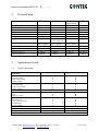
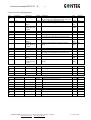
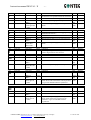
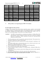
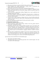
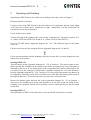
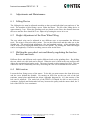
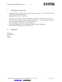
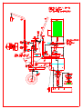
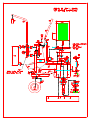
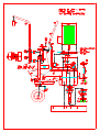
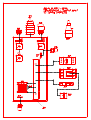
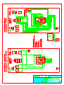
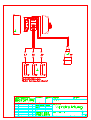
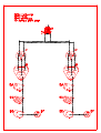
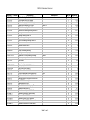
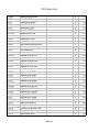
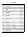
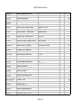
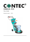
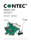
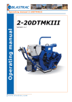
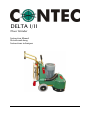
DELTA I/II
Floor Grinder
Instruction Manual
Betriebsanleitung
Instructions techniques
Instruction manual DELTA I / II
-2-
Index
1. EU-Declaration of Conformity
...3
2. Technical data
...4
3. Application of tools
...4
3.1 General applications
...4
3.2 Application of diamond discs
...5
4. Safety rules for the operation of the floor grinder
...8
5. Operating and Grinding
...9
6. Adjustments and Maintenance
…11
5.2
Height Adjustment of the Rear Wheel Wing
…11
5.3
Shifting the rear wheel axis and thereby regulating
the load on the discs and tools.
…11
5.4
Belt tension
…11
7. Changing of the tools
…12
8. Appendix
…12
CONTEC GmbH Hauptstrasse 146, 57518 Alsdorf, Deutschland/ Germany/ Allemagne
[email protected], www.contecgmbh.com
© CONTEC 2006
Instruction manual DELTA I / II
-3-
CONTEC GmbH
Hauptstrasse 146
57518 Alsdorf
1.
EU-Declaration of Conformity
According to the Machine Directive 98/37/EC (89/392/EWG), Appendix II A
We hereby declare that the machine
Type:
Name:
Floor Grinder
Delta I and Delta II
conforms with the following standards which have been valid at the date written below:
EC-Directive 98/37/EC (89/392/EEC), in its current wording
EC-Directive 89/336/EEC, in its current wording
EC-Directive 73/23/EWG (89/392/EEC), in its current wording
List of the essential harmonised standards:
EN 12100
EN 418
EN 953
EN 60204 Part 1
EN 1050
„Safety of machines
„Emergency-Stop-Devices“
„Separating safety devices“
„Electric equipment of machinery, general requirements“
„Guiding principles for the risk judgement“
Alsdorf, 10.04.2004
______________________________
(Place and date)
(Authorized signature)
J. Greb – Construction department
_________________________
(Name and function of the authorized person)
CONTEC GmbH Hauptstrasse 146, 57518 Alsdorf, Deutschland/ Germany/ Allemagne
[email protected], www.contecgmbh.com
© CONTEC 2006
Instruction manual DELTA I / II
2.
-4-
Technical data
DELTA I
DELTA II
Grinding width
Width
Length
Hight
Weight
Hose ¢
Motor
250 mm
45 cm
105 cm
100 cm
115 kg
50 mm
5.5 kW
490 mm
55 cm
105 cm
100 cm
175 kg
70 mm
Electric supply
400 V, 3 phases
480 V, 3 phases
Honda engine
6.8 kW, 1000 U/min
8.0 kW, 2000 U/min
400 V, 3 phases
480 V, 3 phases
-
4.3 m/s2
4.3 m/s2
Noise level Lwa *
99 dB(A)
99 dB(A)
Noise level Leq *
99 dB(A)
88 dB(A)
* Data: VÜA Verein zur Überwachung technischer Anlagen e.V.
Average value of acceleration ahv *
3.
Application of tools
3.1
General applications
Tool Diamond
Application
Grinding of plain floors,
- Smooth surface
- Semi rough surface
- Rough surface
Levelling of uneven surfaces
- Smooth surface
- Semi rough surface
- Rough surface
Levelling of Steps, corners, joints etc.
Renovation
Repair
Faults in concrete
Grinding of
- Hard concrete
- Oily and greasy floors
- Painted floors
- Epoxy coatings
Removal of floor surfaces up to 5 mm
Removal of carpet and tile glue
Grinding of asphalt
A Suitable
B Less suitable
DELTA II
Single speed
490 mm
55 cm
105 cm
100 cm
165 kg
70 mm
7.5 kW
DELTA IIP
490 mm
55 cm
105 cm
100 cm
160 kg
70 mm
-
400 V, 3 Phases
480 V, 3 phases
4.3 m/s2
99 dB(A)
99 dB(A)
11 PS
9.3 m/s2
106 dB(A)
95 dB(A)
Tungsten carbide grit
A
A
A
C
B
A
A
A
B
B
A
A
A
A
A
A
A
B
B
B
A
A
A
A
A
C
B
C
B
A
A
C
A
B
C Unsuitable
CONTEC GmbH Hauptstrasse 146, 57518 Alsdorf, Deutschland/ Germany/ Allemagne
[email protected], www.contecgmbh.com
© CONTEC 2006
Instruction manual DELTA I / II
3.2
-5-
Application of diamond discs
CONTEC GmbH Hauptstrasse 146, 57518 Alsdorf, Deutschland/ Germany/ Allemagne
[email protected], www.contecgmbh.com
© CONTEC 2006
Instruction manual DELTA I / II
-6-
Correct tool for each application
Pos
1
First step
CA1
Shape Comment
Grit
square Hard segment and rough diamond grit size. If
the floor has to be polished better star with CA2.
square Like CA1 but finer diamond grit size.
60/80
MBC0+ to
round Metal-bond polishing up to the required finish
16 to
MBC4
500
Polishing
Polymer-bond polishing up to the required finish 800 to
buttons grit 800
5000
to 3000
Method
dry
First step
Cs 16
Next steps
Grit
16
Method
dry
Cs40
square
MBC2 to
round
MBC4
Polishing
buttons grit 800
to 3000
40
150 to
500
800 to
5000
dry
dry
Grit
16
Method
dry
dry
dry
Polymer-bond polishing up to the required
finish
40
150 to
500
800 to
5000
Comment
Removing of PU-coatings
Grit
Method
6 or 16 dry
CA2
Pos
2
Pos
3
Pos
4
Next steps
Shape
square
First step
Cs16
Next steps
Cs40
square
MBC2 to
round
MBC4
Polishing
buttons grit 800
to 3000
First step
Cs06 or Cs16
Next steps
Shape
square
Shape
square
PCD
5
First step
Cs06 or Cs16
Next steps
Surface grinding of PU-coatings
Shape
square
Comment
Removing of Epoxy-coatings
6
PCD
square
square
Next steps
Shape
square
Surface grinding of Epoxy-coatings
Epoxy with a lot of sand
Comment
High machine wear and tear
CONTEC GmbH Hauptstrasse 146, 57518 Alsdorf, Deutschland/ Germany/ Allemagne
[email protected], www.contecgmbh.com
dry
dry
dry
dry
16
dry
Grit
Method
6 or 16 dry
High machine wear and tear
Cs16
CA1
First step
Cs06 or Cs16
Comment
Soft segment and rough diamond grit size. If the
floor has to be polished better star with Cs40.
Like Cs16 but finer diamond grit size.
Metal-bond polishing up to the required finish
square
PCD
Pos
Polymer-bond polishing up to the required
finish
High machine wear and tear
Cs16
Pos
Comment
Soft segment and rough diamond grit size. If the
floor has to be polished better star with Cs40.
Like Cs16 but finer diamond grit size.
Metal-bond polishing up to the required finish
dry
dry
dry
16
dry
Grit
Method
6 or 16 dry
dry
© CONTEC 2006
Instruction manual DELTA I / II
Pos
First step
CA1
7
Next steps
Shape
square
Cs40
square
MBC2 to
round
MBC4
Polishing
buttons grit 800
to 3000
Pos
First step
PCD
8
Pos
9
Pos
10
Pos
11
Pos
12
Next steps
Shape
Cs16
Cs40
MBC2 to
MBC4
Polishing
buttons Grit
800 to 3000
square
square
round
First step
PCD
Next steps
First step
MBC1
First step
MBC1
First step
MBC1
-7-
Comment
Hard segment and rough diamond grit size. If
the floor has to be polished better star with CA2.
Like CA1 but finer diamond grit size.
Metal-bond polishing up to the required finish
Polymer-bond polishing up to the required
finish
Grit
16/18
Method
dry
40
150 to
500
800 to
5000
dry
dry
dry
Comment
Grit
Grinding (cutting) to expose the aggregate. High
machine wear and tear
16
40
Metal-bond polishing up to the required finish
150 to
500
Polymer-bond polishing up to the required
800 to
finish
5000
Method
dry
Shape
Comment
Difficult grinding because of high bitumen
content. High machine wear and tear
Grit
Method
dry
Next steps
Shape
round
Comment
Grit
40
Method
dry
MBC2 to
MBC4
Polishing
buttons Grit 60
to 5000
round
150 to
500
Polymer-bond polishing up to the required finish 60 to
5000
dry
Next steps
Shape
round
Comment
Grit
40
Method
dry
MBC2 to
MBC4
Polishing
buttons grit 60
to 5000
round
150 to
500
60 to
5000
dry
Next steps
Shape
round
Comment
For Terrazzo tiles
Grit
40
Method
dry
square
For Terrazzo screed
150 to
500
60 to
5000
dry
Cs16 or Cs40
MBC2 to
MBC4
Polishing
buttons grit 60
to 5000
Polymer-bond polishing up to the required
finish. Most of the time marble will be polished
to a grit size 400/800 and then crystallised
round
Polymer-bond polishing up to the required
finish. Most of the time Terrazzo will be
polished to a grit size 400/800 and then
crystallised
CONTEC GmbH Hauptstrasse 146, 57518 Alsdorf, Deutschland/ Germany/ Allemagne
[email protected], www.contecgmbh.com
dry
dry
dry
dry
wet
wet
wet
© CONTEC 2006
Instruction manual DELTA I / II
Diamondquality
CA1
CA2
Cs06
Cs6/16
Cs16
Cs40
C1
C2
MBC0+
MBC0
MBC1
MBC2
MBC3
MBC4
4.
Colour
Order- No.
Brown
Green
Red
Gold
Silver
Blue
Yellow
Purple
Silver
Brown
Black
Green
Blue
Yellow
18-21-CA1
18-21-CA2
18-21-Cs06
18-21-Cs6/16
18-21-Cs16
18-21-Cs40
18-21-C1
18-21-C2
18-21-MBC0+
18-21-MBC0
18-21-MBC1
18-21-MBC2
18-21-MBC3
18-21-MBC4
-8Polishing
button Grit
30
60
120
220
400
800
1800
3000
5000
60
120
220
400
800
1800
3000
Colour
Order- No.
Brown
Green
Black
Red
Yellow
White
Blue
Grey
Pink
Green
Black
Red
Yellow
White
Blue
Grey
18-21-30-N
18-21-60-N
18-21-120-N
18-21-220-N
18-21-400-N
18-21-800-N
18-21-1800-N
18-21-3000-N
18-21-5000-N
18-21-60-T
18-21-120-T
18-21-220-T
18-21-400-T
18-21-800-T
18-21-1800-T
18-21-3000-T
Safety Rules for Operating the DELTA Grinder
Intended application and operation:
Grinding of flat, horizontal, dry surfaces that are typically concrete, asphalt or steel and with
or without a coating. For optimum performance and compatibility always use tools supplied
by CONTEC. Operation of the grinder outdoors is only permitted if the weather is dry. The
DELTA II-P with Honda engine is only allowed to be operated outdoors.
Attention !
The DELTA floor grinders are constructed according to existing safety rules
and regulations. These technical precautions must not be removed or changed
under any circumstances. While operating the grinder the following points
should also be kept in mind:
1. The floor grinder may only be operated by trained professionals. The operators have
read and be familiar the contents of this manual.
2. The floor grinder must not be operated in areas where the hazard of explosion or fire
exists.
3. The grinder should only be activated when the tools are lifted from the floor by the
lifting device (Appendix diagram No. 63 and 65).
4. The tools and discs may be hot after use. Take care when changing them.
5. Never operate the floor grinder on a sloping surface.
6. Take care when moving the machine on a sloping surface, substantial rolling forces
can be produced.
7. The hooks of a crane can only be placed in the lifting points described in the appendix
„Lifting Points“.
8. The machine should always be stored in a warm, dry place when not in use.
9. The floor grinder may only be operated with the dust guard (Appendix diagram No.1).
10. Only CONTEC original tools and spare parts are to be used.
CONTEC GmbH Hauptstrasse 146, 57518 Alsdorf, Deutschland/ Germany/ Allemagne
[email protected], www.contecgmbh.com
© CONTEC 2006
Instruction manual DELTA I / II
-9-
11. The grinder should only be operated with all safety guards in position.
12. When changing tools, during transportation, cleaning, repair or maintenance the
grinder must be disconnected from the mains.
13. The operator must never leave the machine unattended during operation.
14. Before leaving the machine all rotary parts must be brought to a standstill. Electric
models must be disconnected from the power supply. Ensure the machine cannot roll
or move by itself.
15. Never wear loose or badly fitting clothing. Flapping sleeves may be pulled into the
machine causing serious injury.
16. The DELTA should be switched off immediately if unusual noises or vibrations are
detected during the operating of the machinery. A thorough check must be carried out
in order to detect the cause.
17. Check the power cables regularly as damage may have occurred while operating the
machine. Always disconnect the cables before examination and treat all electrical parts
with extreme care.
18. After any maintenance and adjustment all safety guards must be refitted.
19. Ear protectors must be worn.
20. Eye protectors must be worn.
21. Safety shoes with steel caps must be worn.
22. When operating the grinder produces large volumes of dust the grinder should be
connected to a suitable dust collector.
23. Depending on the floor (floor coating) grinding can produce gases. The operator must
be held responsible if the gases generated are hazardous and whether protection is
necessary. Grinding floors containing asbestos is especially dangerous and can cause
health problems. Special masks must be worn which keep the breathing air clean. A
dust collector must be used and should be equipped with filters suitable for asbestos
dust.
24. The floor must be brushed before grinding to prevent loose material collecting in the
tools and then being thrown out with force. Anchor screws and bolts in the floor can
also be seen better if the area is clean. If the grinding head strikes an anchor screw or
bolt then serious damage can be caused to the machine and grinding head.
Special safety rules for the DELTA II-P with Honda engine
1. Only operate the machine outdoors.
2. The Honda engine turns very hot during operation. Never touch the engine. Also read
the manual of the Honda engine.
CONTEC GmbH Hauptstrasse 146, 57518 Alsdorf, Deutschland/ Germany/ Allemagne
[email protected], www.contecgmbh.com
© CONTEC 2006
Instruction manual DELTA I / II
5.
- 10 -
Operating and Grinding
Operating the DELTA has to be carried out according to the safety rules in Chapter 3.
Bring the grinder to the floor.
Connect a hose to the DELTA and to the dust collector. It is important, that the entire length
of the hose has no holes and is completely air tight. Small holes or a bad connection can
extremely decrease the performance
Check all the electric cables.
Connect the plug of the grinder to the socket of the extension lead. The power required is 32
A, 3 phase, 50 Hz for the DELTA II and 16 A, 3 phase, 50 Hz for the DELTA I.
Press the START button (Appendix diagram No. 121). The indicator lamp in the button
comes on.
Lift the tools from the floor using the lift bar (Appendix diagram No. 63 and 65).
!
If you start the machine with the grinding tools placed on the floor you may damage the discs
and/or parts of the grinder.
Starting DELTA II
Turn the motor switch (Appendix diagram No. 123) to Position 1. The motor begins to turn.
Make sure that the ventilator on the topside of the motor is turning in the correct direction as
indicated by the arrow. If the motor rotates in the wrong direction, turn the switch back to the
O position. Press the emergency STOP button (Appendix diagram No. 125) and disconnect
the plug (Appendix diagram No. 150). The plug is a reverse plug which means two phases can
be swapped by inserting a screw driver in between two of the pins and twisting them round to
the opposite direction. This allows the motor to turn in the correct direction.
Restart the machine again and turn the switch (Appendix diagram No. 121) to Position 1.
Now lower the grinding tools slowly and carefully on to the floor using the lifting device.
Grinding is now possible. Switch over to position 2 and see which speed gives the best result
on the floor.
Starting DELTA I
Same procedure as DELTA II besides there is only an ON/OFF switch for one speed.
CONTEC GmbH Hauptstrasse 146, 57518 Alsdorf, Deutschland/ Germany/ Allemagne
[email protected], www.contecgmbh.com
© CONTEC 2006
Instruction manual DELTA I / II
6.
- 11 -
Adjustments and Maintenance
6.1 Lifting Device
The Lifting device must be adjusted according to the type and individual wear and tear of the
tools. The machine is lifted using a screw under the motor. The lift of the lifting device is
approximately 5 cm. When the grinding tools are placed on the floor, the distance between
the screw and the floor should be 2 cm. Adjust it by turning the screw in or out.
6.2 Height Adjustment of the Rear Wheel Wing
The rear wheel wing can be adjusted in two different ways to accommodate the different
tools. The wing is secured to three points. Two on the frame itself and the other one to the
Spindle nut. The actual height adjustment - fine and standard settings - of the grinding discs
can be achieved by turning the hand wheel of the spindle. By turning the wheel the height
can be set lengthways. Therefore avoiding uneven wear on the discs.
6.3 Shifting the rear wheel axis and thereby regulating the load on
the discs and tools.
Different floors and different tools require different loads on the grinding discs. By shifting
the rear wheel axis, this load can be altered. When the axis is fixed in the rear position, this
allows the maximum load on the tools. The more forward position means less load. The rear
wheel axis can be comfortably moved by loosening the two screws behind the rear wheels.
6.4 Belt tension
Loosen the four fixing screws of the motor. To do this you must remove the front belt cover
and the cover behind the Spindle. By turning an M10 Nut on the rear side of the belt
tensioner (metal plate underneath the motor Appendix diagram No. 101) the tension of the
belt can be adjusted. The tooth belt of the DELTA II should be able to move halve a
centimetre forwards and backwards half way between the pulley and the motor shaft, the V
belt of the DELTA I one centimetre.
CONTEC GmbH Hauptstrasse 146, 57518 Alsdorf, Deutschland/ Germany/ Allemagne
[email protected], www.contecgmbh.com
© CONTEC 2006
Instruction manual DELTA I / II
7.
- 12 -
Changing of the tools
Attention: Before working on the grinder bring the motor to a total stand still and
disconnect from the power supply.
Attention: Tools can be hot after use.
-
8.
Tilt the machine onto the back wheels and rest it on the bar underneath the control panel.
All brackets for segment plates (Appendix diagram No. 11) are secured to the tool
brackets (Appendix diagram No. 67) by 3 Allen screws.
By loosening the screws the discs can be removed.
Check the grinding tool for wear or damage ready for the next application.
Fix new tools according to the appendix „Tools“.
Appendix
Diagrams
Wire diagram
Tools
Part list
CONTEC GmbH Hauptstrasse 146, 57518 Alsdorf, Deutschland/ Germany/ Allemagne
[email protected], www.contecgmbh.com
© CONTEC 2006
DELTA II Stückliste / Parts List
Artikel-Nr. / Part-No.
70-23-14-50
14-17-10-05
90-25-10-01
14-10-10-06
14-17-10-08
14-17-10-04
61-20-62-07
14-17-10-02
14-17-10-01
14-17-10-03
70-25-01-71
14-10-01-00
70-25-01-70
70-40-8M-50
61-20-60-04
90-24-20-12-30
70-26-8M-50-U
70-24-13-60
70-26-8M-50-38
70-22-8M-50-US
14-10-02-00-H
14-10-02-00
14-10-11-10
61-50-10-41
14-10-07-01
14-10-08-05
60-30-10-50
80-52-22-50
60-32-20-04
14-10-04-01
18-21-MBC1
18-21-MBC2
18-21-PKD-S
18-21-MBC0+
18-21-MBC4
Description 1
Rubber Sealing Dust Guard Delta II
Tool Bracket Delta I+II/Omega
Rubber Coupling Delta I+II/Omega
Spacer at the Bracket for Clutch
Bracket for coupling Delta I+II
Bottom lid of Bearing Housing Delta I+II
Bearing in the Drive Delta I+II
Bearing Housing Delta I+II
Axis Bearing Housing Delta I+II
Top lid of Bearing Housing Delta I+II
Dusthose at the Machine 70 mm Diameter
Machine frame Delta II
Dusthose at the Machine 70 mm Diameter
Pulley on bearing housing
Bearing in reverse pulley Delta I+II
Taperlock for Pulley Bearing Housing
Reverse pulley Delta II
Belt Delta II
Motor pulley Delta II
Motor pulley Delta II USA Version
Belt Cover Petrol Delta II
Belt Cover Electric Delta II
Lift arm underneath the machine new
Eye Scrw for Quick Lever Delta bottom
Swinging arm for axis Delta II new Vers.
Axis DELTA II new style
Handle screw M10-55
Wheel Delta I+II with blu-grey Tire
Spindel screw Delta I+II
Lid under control panal Delta I+II
Diamond Plate MBC1 Black round
Diamond Plate MBC2 Green round
Diamond Plate PCD in Segment
Diamond Plate MBC0+ Silver round
Diamond Plate MBC4 Yellow round
Description 2
Delta I/II
Black Colour Delta II Petrol Version
Black Colour Delta II
Delta II
style
one
Seite 1 von 5
Nr-No
1
3
5
7
9
11
13
14
15
19
20
21
22
23
24
25
26
27
29
29
31
31
33
35
37
39
41
43
47
49
51
51
51
51
51
Weight KG
1,3
1,22
0,5
0,08
0,8
0,57
0,34
3,03
1,53
0,52
0,37
0
0,37
1,26
0,075
0,65
0,87
0,5
0,9
0
0
0
0,89
0,04
3,55
2,25
0,06
2,36
0,7
0,73
0,26
0,26
0,26
0,26
0,26
DELTA II Stückliste / Parts List
18-21-MBC3
18-21-CA1
18-21-C2
18-21-CA2
18-21-C1
18-21-MBC0
18-21-CS6/16
18-21-CS40
18-21-CS16
18-21-CS06
18-10-05-02
14-10-09-03
18-10-29-11
90-21-95-50
18-21-5000-N
18-21-120-T
18-21-400-N
18-21-400-T
18-21-60-N
18-21-60-T
18-21-800-N
18-21-220-T
18-21-220-N
18-21-30-N
18-21-1800-N
18-21-3000-N
18-21-3000-T
18-21-1800-T
18-21-800-T
18-21-30-T
18-21-120-N
14-10-11-01
90-21-95-51
61-50-10-40
14-10-11-02
70-21-26-10
Diamond Plate MBC3 Blue round
Diamond Plate CA1 Brown
Diamond Plate C2 Aubergine
Diamond Plate CA2 Green
Diamond Plate C1 Yellow
Diamond Plate MBC0 Brown round
Diamond Plate CS6/16 Gold
Diamond Plate CS40 Blue
Diamond Plate CS16 Silver
Diamond Plate CS06 Red
Height Adjustment Screw Omega/Delta II
Spacer Height Control Delta/Omega
Plate for polishing Dotts
Level Adjustment Wheel Delta I+II
Resignbond Wet Grid 5000 Pink
Resignbond Dry Grid 120 Black
Resignbond Wet Grid 400 Yellow
Resignbond Dry Grid 400 Yellow
Resignbond Wet Grid 60 Green
Resignbond Dry Grid 60 Green
Resignbond Wet Grid 800 White
Resignbond Dry Grid 220 Red
Resignbond Wet Grid 220 Red
Resignbond Wet Grid 30 Brown
Resignbond Wet Grid 1800 Blue
Resignbond Wet Grid 3000 Grey
Resignbond Dry Grid 3000 Grey
Resignbond Dry Grid 1800 Blue
Resignbond Dry Grid 800 White
Resignbond Dry Grid 30 Brown
Resignbond Wet Grid 120 Black
Bracket for Lift Pipe Delta I+II
Revolving Pin for Handwheel Delta
Eye Scrw for Quick Lever Delta Top one
Lift pipe at the top of the machine
Rubber for Handle Delta I+II
51
51
51
51
51
51
51
51
51
51
51
53
55
55
57
57
57
57
57
57
57
57
57
57
57
57
57
57
57
57
57
57
57
61
63
65
Seite 2 von 5
0,26
0,26
0,26
0,26
0,26
0,26
0,26
0,26
0,26
0,26
0,33
0,05
0,2
0,38
0,09
0,09
0,09
0,09
0,09
0,09
0,09
0,09
0,09
0,09
0,09
0,09
0,09
0,09
0,09
0,09
0,09
0,035
0,08
0,04
0,54
0,06
DELTA II Stückliste / Parts List
70-26-50-00
14-10-05-01
14-10-05-00
60-30-10-30
70-26-30-00
51-10-10-00
14-10-06-01
51-20-30-03
18-10-08-01
14-10-13-01
80-20-62-80
14-10-03-01-H
14-10-03-01
14-10-03-01-US
56-GXV-11
50-20-20-75
50-20-68-80
50-22-68-80
56-GXV-99
51-20-21-04
50-20-23-01
51-20-30-01
50-10-10-100
51-20-32-04
51-20-31-05
50-20-30-03
50-20-23-02
50-20-23-09
50-20-33-07
50-20-33-08
50-20-20-15
14-10-01-99
18-21-36-T0
14-10-29-01
14-10-29-02
14-10-29-03
Vibration blocks for Handle DELTA II
Bracket for handle right side Delta I+II
Bracket for handle left side Delta I+II
Handle screw M10-25
Vibration blocks DELTA I
Switch Box For Motor Protective Single
Handle Delta I+II
Low Voltage Protective 400 V Delta I/II
Height Adjustment Screw Frontwheel
Front Wheel Bracket only Delta II
Frontwheel Omega/Delta
Belt tensioner Delta II for Honda Petrol
Belt tensioner Delta I+II
Belt tensioner Delta II for Baldor Motor
Motor 11 HP for Delta II
Motor DELTA II 7,5 KVA, 400 Volt
Motor Delta II 6,8/8 KVA, 400 Volt
Motor Delta II 6,8/8 KVA, 200 Volt
Lever for Petrol Engine Delta/Omega
Dalander-Switch Delta II+I
Emergency Switch Delta II new Version
Motor Protective Delta II, 6,8/8 KW,
Control Panel only Frame Delta II
Main Contactor Delta I+II
Main Contactor Delta II US Version
Circuit Breaker Control C2 Delta II
Start Button Delta II new Version
Mounting Adapter for Switches Delta I/II
Contact Element K10 Delta I/II new
Contact Element M22-K01 Delta I/II
Reverse Plug 32 A, 400 Volt Delta II
Conversion Kit for Delta II from two to
Diamond Disk Silver 12 Segments Omega
Bracket for Tungston Disk Delta
Bracket for Carborundum Disk Delta
Bracket for Carborundum Disk Delta
Speed Delta I/II
Single Speed
Omega/Delta
Motor
10 HP US
Single Speed
3 Phase Japan
Mai 2003
400 Volt
with all holes
Baldor 10 HP Motor
2003
new Version Mai 2003
Version Mai 2003
new Version Mai 2003
one Handwheel
very hard Concrete
Seite 3 von 5
71
73
74
75
77
78
81
81
91
93
95
101
101
101
103
103
103
103
105
123
125
127
128
129
129
131
131
143
145
147
150
0
1,3
1,3
0,05
0,05
0
4
0
0,33
2,5
0,77
13
1,95
4,4
0
0
72
72
0,2
0
0
0
0
0
0
0
0
0
0
0
0
0
6
3,29
3,29
3,29
DELTA II Stückliste / Parts List
14-10-50-03
14-21-30-T0
14-16-29-01
14-16-29-02
14-16-50-04
14-20-99-00
14-20-99-01
14-20-99-16
14-21-30-H
14-21-36-T0
14-21-6W
14-21-GB-1
14-21-GB-2
14-21-GB-3
14-21-MBC-120
14-21-30-00
90-09-SW-6
90-09-SW-5
70-23-14-50-H
18-10-11-00
14-10-14-00
14-10-11-03
14-10-29-05
14-10-29-06
14-10-13-00
14-10-08-00
14-13-11-03
14-17-10-00
14-13-07-01
70-24-13-60 30 mm
70-24-14-40 30mm
50-10-10-40
50-20-20-06
50-20-30-061
50-20-68-82
50-20-68-81
Bracket for Polishing Tools Delta II
Diamont Disk Silver 12 Segments Delta
Tungston Ring rough Delta
Tungston Ring fine Delta
Hydrit Floor, very hard Concrete
Diamont Disk Blue 20 Segments Asuga
Diamont Disk Red 20 Segments Asuga
Diamont Disk Red 16 Segments Asuga
Diamont Disk Brown 12 Segments Delta
Diamont Disk Silver 6 Segments Delta
Diamont Disk Red 12 Segments Delta
Diamont Disk Aubergine 12 Segments
Diamont Disk Orange 12 Segments Terazzo
Diamont Disk White 12 Segments Delta
Diamont Disk Black 12 Segments
Diamont Disk Blue 12 Segments Delta
Allenwrensch 6 mm Omega/Delta
Allenwrensch 5 mm Omega/Delta
Rubber Sealing Dust Guard Delta II
Extra weight 6 KG for Omega/Delta
Standard concrete
epoxy and PU Floors
epoxy and PU Floors
Agressive concrete
Hydrit Floor, very hard Concrete Asphalt
Epoxy / Glue
Terazzo Delta Rough Grade
Delta Fine Grade
Fine finish Polishing
Terazzo Delta Fine Grade
Standard concrete
Lift arm underneath the machine old
Grinder Head for Flails Delta II round
Bracket disc Plates Delta
Front Wheel for Grinder Head Delta II
Axis DELTA II old style
Lifting rod Delta I+II
Bearing Housing complete Delta I+II
Swinging arm for axis old Version
Belt Delta II, 30 mm
style
type with 6 Blocks
for Flails
Stainless steel pipe.
Control panal DELTA II
Label Mount (Start) 111 Delta II
Switch with Lamp complete Delta II
Motor Delta II 6,8/8 KVA, 400 Volt
Motor Delta II 6,8/8 KVA, 400 Volt
Seite 4 von 5
0
3,67
1,46
1,25
1,1
4,2
0
0
3,67
3,67
3,67
3,67
3,67
3,67
3,67
3,67
60
40
1,6
6
1,52
0
0
2,1
2,5
0
840
6,3
0
300
350
0
0
0
72
72
DELTA II Stückliste / Parts List
50-20-20-02-N
0
Seite 5 von 5