1
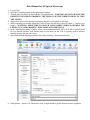
Brief Manual for 3D Optical Microscope
1. Log in FOM
2. Open the Vision64 program on the instrument computer.
3. Turn the objective lenses to start with the 5X magnification – WARNING: DO NOT CHANGE THE
OBJECTIVE LENSES BY GRABBING THE LENSES, USE THE TURRET WHEEL TO TURN
THE LENSES.
4. Adjust the Z-axis to raise the objective lenses, and place your sample on the stage.
5. While watching your sample, adjust the Z-axis to lower the objective lenses to within a ~5 mm of your
sample – WARNING: MAKE SURE TO WATCH YOUR SAMPLE WHILE LOWERING THE
LENSES, TO AVOID CRASHING THE LENSES INTO THE STAGE.
6. In the “Measurement Setup” window, select your measurement mode, PSI or VSI. PSI is typically used
for very smooth surfaces, with features that are less than 160 nm. VSI is typically used to measure
features between 160 nm and 10 mm.
7. Open Measurement Parameters window from More Settings – Measurement button
8. Scan Options – Speed is 1X; Backscan is 5um; Length should be greater than the surface roughness.
1 99. Press thee AUTO buttton on the “Intensity”
“
window,
w
to aautomaticallyy adjust the brightness oof the samplee
(if there are red dotts present on the screen
n, then the sample is oover-saturateed with lighht). Once thee
intensity is optimized
d, press the AUTO
A
butto
on again to tuurn this settiing off.
110. Slowly adjust the Z-aaxis to bring
g your sample into focus till you can see the interrference frinnge.
111. Use the tilt
t knobs on
n the instrum
ment to adjusst the tilt andd reduce thee fringes present on the ssample. Firsst
adjust the knob on th
he left side of
o the instru
ument, to maake the fringges horizontal. Then adjjust the knob
b
on the ceenter of the instrument to reduce th
he fringes. T
The Z-axis should also be adjustedd during this
process, to
t keep the sample
s
in focus. (See beelow):
112. Once thee focus and tilt
t have been
n adjusted, the
t magnificcation can bee increased ((using the tuurret wheel to
o
rotate thee objective lenses).
l
Mak
ke sure that the magnificcation selectted in the “M
Measuremennt Setup” tab
b
correspon
nds to the ob
bjective lens in use.
113. Click thee Measurem
ment button from
f
the top panel to colllect data.
114. In the Daata Analysis window, select the “Terrms Removaal” option frrom the Anallysis Toolboox in order to
o
calibrate the data and
d perform tillt correction
n in the imagge. If the sam
mple is comppletely flat, tthen you can
n
select Tiilt Only (P
Plane Shift) option by right clickiing on “Terrms Removval” and sellecting “Ediit
Settings””. If the samp
ple is not flaat, then you can
c select thhe Tilt Onlyy (Plane Shifft) option annd also check
k
the “Use Terms Mask” option. You
Y can then
n click the “E
Edit Mask” bbutton to select the areaa you want to
o
he tilt correction.
use for th
115. In the Data
D
Analysis window, you
y can select the “3D
D Plot” buttoon on the leeft side of tthe screen to
o
generate a 3D imagee of your sam
mple. The scrolling wheeel on the m
mouse allowss you to zooom in or outt,
and you can also in
ncrease or decrease
d
thee magnificattion using th
the arrows oon the rightt side of thee
t x- and y-axes
y
of thee plot couldd be used to obtain 1D profiles of a
window. The slider arrows on the
selected region
r
of thee graph.
116. For a big
g area, you caan use stitch
hing function
n by Enable Stitching.
117. You can save the raw
w data in C:/USER-DAT
TA/your foldder with exteension of OP
PDx. You alsso can exporrt
X and Y profile as CSV file.
118. Raise thee objective leenses and rem
move your sample
s
119. Log off FOM
F
2