1
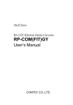
Ver.1.00
F&eIT Series
Isolated Digital Input Module
DI-8(FIT)GY
This product is an expansion module (device module) that adds
digital signal input interfaces to one of various types of
controllers. The product is used in combination with the I/O
controller module <CPU-CAxx(FIT)GY> (*1) or microcontroller
unit <CPU-SBxx(FIT)GY> (*1) in the F&eIT Series.
This product can perform a maximum of 8 points of
Optocoupler isolated input per module.
(12 - 24 VDC specified)
*1
This module is available in different product models. "x" in each model number
represents a blank or one alphanumeric character. This is applicable to the rest of this
document.
* Specifications, color and design of the products are subject to
change without notice.
Features
Specification
This product can perform 8-point digital signal input, treating 8
points as a group.
Specifications
Input section is ready to accept both the current sinking output
and current source output.
Input section
Input format
Isolated input operations using an optocoupler improves noise
immunity.
A rotary switch allows you to set device IDs, making it easy to
keep track of device numbers.
Like other F&eIT series products, the module has a 35mm DIN
rail mounting mechanism as standard. A connection to a
controller module can be effected on a lateral, stack basis in a
unique configuration, which permits a simple, smart system
configuration without the need for a backplane board.
Packing List
Specifications
DI-8(FIT)GY
Item
Optocoupler isolated input
(compatible with current sink output and current source
output)
Input resistance
3kΩ
Input ON current
3.4mA or more
Input OFF current
0.16mA or less
Number of input signal points 8 points (8 points/common)
Response time
Within 1msec
External circuit power supply 12 - 24VDC (±15%)
(4mA/12V - 8mA/24V per channel)
Common section
Interrupt level
Using CPU-SBxx(FIT)GY: IRQ 5, 7, or 9
External circuit power supply 12 - 24VDC (±15%)
Internal current consumption 5VDC(±5%) 150mA(Max.) *1
Allowable distance of signal Approx. 50m (depending on wiring environment)
extension
Physical dimensions (mm)
25.2(W) x 64.7(D) x 94.0(H) (exclusive of protrusions)
Weight of the module itself
100g
Module connection method
Stack connection by means of a connection mechanism
standard with the system
Module installation method
One-touch connection to 35mm DIN rails
(standard connection mechanism provided in the system)
Applicable wire
AWG 28 - 16 wire type: 0.32 - 1.30mm
Applicable plug
FRONT-MC 1,5/12-STF-3,81 (made by Phoenix Contact
Corp.)
3.81mm-pitch, rated current: 8A (Max.)
*1 The stack connector accepts currents of up to 3.0A (Max.).
Installation Environment Requirements
Item
Module[DI-8(FIT)GY] …1
First step guide … 1
CD-ROM [F&eIT Series Setup Disk] *1…1
Interface connector plug…1
*1
The CD-ROM contains various software and User’s Guide.
DI-8(FIT)GY
Operating temperature
Requirement description
0 - 50°C
Storage temperature
-10 - 60°C
Operating humidity
10 - 90%RH (No condensation)
Floating dust particles
Not to be excessive
Corrosive gases
None
Noise immunity
Line-noise *1
AC line/2kV, Signal line/1kV
(IEC1000-4-4Level 3, EN61000-4-4Level 3)
Static
Contact discharge/4kV (IEC1000-4-2Level 2,
electricity
EN61000-4-2Level 2)
resistance
Atmospheric discharge/8kV (IEC1000-4-2Level 3,
EN61000-4-2Level 3)
Vibration
Sweep
10 - 57Hz/semi-amplitude 0.15mm, 57 - 150Hz/2.0G
resistance
resistance
80minutes each in X, Y, and Z directions
(JIS C0040-compliant, IEC68-2-6-compliant)
Impact resistance
15G half-sine shock for 11ms in X, Y, and Z directions
(JIS C0041-compliant, IEC68-2-27-compliant)
*1 When using a POW-AD22GY
1
Ver.1.00
CAUTION
When connecting one of the modules to a controller module,
the internal current consumption should be taken into
account. If the total current exceeds the capacity of the
power supply unit, the integrity of the operation cannot be
guaranteed. For further details, please see the Controller
Module manual.
Block Diagram
Functions and control method by
controller connected
This product can be connected to a variety of controllers.
Supported controllers
Microcontroller Unit
I/O Controller Module
Monitoring & Control Server Unit
Monitoring & Control Server Unit
:
:
:
:
CPU-SBxx(FIT)GY
CPU-CAxx(FIT)GY
SVR-MMF2(FIT)
SVR-MMF(FIT)GY
Check each controller to which the module can be connected
as well as the method of controlling the module when
connected to that controller.
Interface Connector IN00 - IN07
Opto-Coupler
I T)
GY
)
MF
(F
FIT
R-M
MF
2(
SV
R-M
SV
Ο
Ο
Ο
Ο
DI-8(FIT)GY
Ο
Ο
Ο
Ο
DO-8(FIT)GY
Ο
Ο
Ο
Ο
0-7
0-7
0-7
0-7
Device ID setting range
U-C
DIO-4/4(FIT)GY
U-S
CP
Control Circuit
O: Permitted
×: Not permitted
CP
Device ID
Bx x
(FI
Tri-State
Buffer
Ax x
T )G
Y
(FI
T)G
Y
Connections to controllers
Physical Dimensions
(1.2)
Control using the I/O address map
Ο
Ο
Control using the memory address map
(1.2)
Ο
FIT Protocol
Control via the Windows driver * API-CAP(W32)
API-SBP(W32)
Control over the web
(as set from within the browser)
*
X
0 1 2 3
4 5 6 7
6
2
COM0
94
NC
0
1
2
3
X COM1
45.0
NC
4
5
6
7
DI-8
3.5
25.2
64.7
4.0
Ο
The API-SBP(W32) is included in the development kit [DTK-SBxx(FIT)GY]; the other
drivers are bundled with each controller.
Control via the Windows driver
For the functions and settings available when using the
Windows driver, refer to the reference manual and online help
for each module.
[mm]
DI-8(FIT)GY
Ο
Control using the memory address map
When connected to the CPU-CAxx(FIT)GY, the module can be
accessed from the host computer over the network. The
module is assigned with its device ID in the memory managed
by the controller module. The application running on the host
computer controls the module by reading/writing the memory
managed by the controller module.
35.0
4
0
Device
ID
Ο
Ο
Control using the I/O address map
When connected to the CPU-SBxx(FIT)GY, the module can
receive I/O instructions directly from the controller module.
14.0
31.5 14
IT)
GY
SV
R-M
MF
2(F
IT)
SV
R-M
MF
(FI
T)G
Y
Stack Connector
CP
U-C
Axx
(F
CP
U-S
Bxx
(FI
T
)GY
Control method by controller connected
Control over the web
You can monitor collected data and manage the log over the
web. You can use your familiar browser to easily make
various settings. For details, refer to the reference manual for
the SVR-MMF2(FIT), SVR-MMF(FIT)GY.
2
Ver.1.00
Example of a Connection to Current Sink Output
Interface Connector
Module
When connecting the Module to an external device, you can
use the supplied connector plug.
To wire the Module, strip the sheath about 9 - 10mm from an
end of the wire and insert the exposed wire into an opening.
Tighten the screw to fasten the inserted wire. Applicable
wires are AWG28 - 16.
X
0 1 2 3
2
4 5
0 1
3
Minus
common
Input
pin
Optocoupler
Current sink
output
External
power supply
12V - 24VDC
Example of a Connection to Current Source Output
9 - 10mm
7
6
3kΩ
Turn the screw to fasten the wire.
4 5 6 7
Device
ID
External circuit
Vcc
How to Connect an Interface Connector
Module
External circuit
Vcc
COM 0
NC
- Applicable wire:
3.81mm pitch, 12-pin type, 8.0A rated current
MC1, 5/12-GF-3.81 [made by Phoenix Contact Corp.]
0
1
2
3
3kΩ
Minus
common
COM1
X NC
4
5
6
7
- Applicable plug:
Front screw type with connector stopper flange
External
power supply
Input
pin
Optocoupler
Current
source output
FRONT-MC 1,5/12-STF-3,81 [made by Phoenix Contact Corp.]
Applicable cable: AWG28-16
DI-8
CAUTION
Removing the connector plug by grasping the cable can
break the wire.
Connection example:
Using Inputs X0
The Module can be connected to an external device using a
12-pin connector that is provided on the Module face.
COM 0 --- +/-COM
N.C.
Input port
plus / minus common
Module side
Signal Layout on the Interface Connector
Input plus common (e.g., connector COM0)
+
External
power supply
12V - 24VDC
-
Input pin (e.g., connector X0)
X 0 --- IN 0
X 1 --- IN 1
Digital Input: 4points
X 2 --- IN 2
Example of Connecting Outputs and Inputs
X 3 --- IN 3
External
power supply
12V - 24VDC
COM 1 --- +/-COM
N.C.
X 4 --- IN 4
X 5 --- IN 5
X 6 --- IN 6
-
+
Digital Input: 4points
X 7 --- IN 7
Intput module
Output module
External Input Circuits
Input section
Figure below shows the input equivalent circuit for the interface
section of this product.
The signal input section consists of an Optocoupler isolated
input (compatible with both current sink output and current
source output).
An external power supply is therefore
required to drive the input section of this module. The power
requirement for the <DIO-4/4(FIT)GY> or <DI-8(FIT)GY> is
about 8 mA per input channel at 24 VDC (about 4 mA at 12
VDC).
Input Circuit
Module
External circuit
Vcc
3kΩ
+/common
Input Input contact
pin
point
Intput
Common minus for output
Setting a Device ID
The controller module distinguishes and keeps track of the
modules that are connected to it by assigning device IDs to
them. Each module, therefore, should be assigned a unique
ID.
A Device ID can be assigned in a 0 - 7 range, so that a
maximum of eight modules can be distinguished.
The factory setting for the Device ID is [0].
Setup Method
A Device ID can be set by turning the rotary switch that is
located on the module face.
A Device ID can be assigned by turning the switch.
Device
ID
6
01
Input contact
point
7
Input
pin
45
3kΩ
Optocoupler
External
power supply
12V - 24VDC
Output
3
Optocoupler
Common plus for intput
Common plus for output
2
DI-8(FIT)GY
Factory setting:
(Device ID = 0)
3