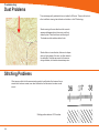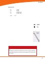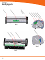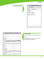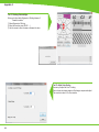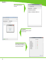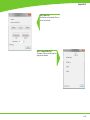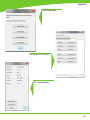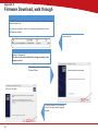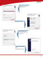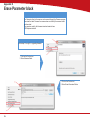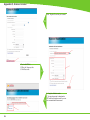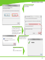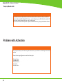
1
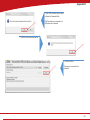
Technical Service Guide
for SD3600
FSM/TSG/001 (1.2)
Revision table
1.0 -> Original Issue of DocumentDecember 15th 2011
CDM
1.1 -> Review updatesJanuary 17th 2012
CDM
1.2 -> Error code list updatedJanuary 19th 2012
CDM
ii
Document Title.:
NA53A Technical Service Guide
Doc. No.:FSM/TSG/001
Prepared by.:CDM
Authorized by.:JR
Distribution.:Tegningsarkiv, Svendborg
Issue revision date.:
0.9 12 December 2011
Scanners covered by this Service Guide.:
NA52A - SD3600
This document is the property of Contex A/S. The data contained herein, in whole or in part, may not be duplicated,
used or disclosed outside the Recipient for any purpose other than to conduct technical evaluation. This restriction does not limit the Recipients right to use information contained in the data if it is obtained from another source
without restriction.
iii
Table of Contents
Introduction to CIS Technology
1-2
CIS Element Design������������������������������������������������������������������������������������������������������������������������������������������������������������������������������������� 1-3
Design2-6
Block Diagram���������������������������������������������������������������������������������������������������������������������������������������������������������������������������������������������� 2-7
Wiring Diagram��������������������������������������������������������������������������������������������������������������������������������������������������������������������������������������������� 2-8
Power Supply layout with measuring points (SMPS)����������������������������������������������������������������������������������������������������������������������������������� 2-9
Keypad �������������������������������������������������������������������������������������������������������������������������������������������������������������������������������������������������������� 2-9
Scanner Controller Board Layout (SULG)�������������������������������������������������������������������������������������������������������������������������������������������������� 2-10
CIS Unit Construction��������������������������������������������������������������������������������������������������������������������������������������������������������������������������������� 2-11
CIS Unit Construction��������������������������������������������������������������������������������������������������������������������������������������������������������������������������������� 2-11
Troubleshooting3-2
Troubleshooting Sequence��������������������������������������������������������������������������������������������������������������������������������������������������������������������������� 3-3
Error codes displayed on Keypad���������������������������������������������������������������������������������������������������������������������������������������������������������������� 3-4
Banding Problems���������������������������������������������������������������������������������������������������������������������������������������������������������������������������������������� 3-5
Image Quality Problems������������������������������������������������������������������������������������������������������������������������������������������������������������������������������� 3-5
Stitching Problems��������������������������������������������������������������������������������������������������������������������������������������������������������������������������������������� 3-6
Part Replacement
4-8
Identifying parts������������������������������������������������������������������������������������������������������������������������������������������������������������������������������������������ 4-10
Part list������������������������������������������������������������������������������������������������������������������������������������������������������������������������������������������������������� 4-11
Power Supply (SMPS)������������������������������������������������������������������������������������������������������������������������������������������������������������������������������� 4-12
LHS Cover������������������������������������������������������������������������������������������������������������������������������������������������������������������������������������������������� 4-13
Scanner Controller Board (SULG)������������������������������������������������������������������������������������������������������������������������������������������������������������� 4-14
Stepper Motor Assy.����������������������������������������������������������������������������������������������������������������������������������������������������������������������������������� 4-16
Tacho Sensor��������������������������������������������������������������������������������������������������������������������������������������������������������������������������������������������� 4-17
Paper and Lid Sensors.������������������������������������������������������������������������������������������������������������������������������������������������������������������������������ 4-18
Complete CIS Unit������������������������������������������������������������������������������������������������������������������������������������������������������������������������������������� 4-19
Power Entry Module����������������������������������������������������������������������������������������������������������������������������������������������������������������������������������� 4-20
USB Cable������������������������������������������������������������������������������������������������������������������������������������������������������������������������������������������������� 4-21
RHS Cover & Keypad������������������������������������������������������������������������������������������������������������������������������������������������������������������������������� 4-22
Damper for CIS Bridge������������������������������������������������������������������������������������������������������������������������������������������������������������������������������ 4-23
Pressure Rollers����������������������������������������������������������������������������������������������������������������������������������������������������������������������������������������� 4-24
Appendix A
A-1
WIDEsystem Service, walk though��������������������������������������������������������������������������������������������������������������������������������������������������������������A-2
Appendix B
B-1
Firmware Download, walk through���������������������������������������������������������������������������������������������������������������������������������������������������������������B-2
iv
Appendix C
Appendix D
Appendix E
Erase Parameter block��������������������������������������������������������������������������������������������������������������������������������������������������������������������������������� B-4
C-1
Scanner Terms�����������������������������������������������������������������������������������������������������������������������������������������������������������������������������������������������C-2
D-1
Error Codes����������������������������������������������������������������������������������������������������������������������������������������������������������������������������������������������������D-2
E-1
Scanner License system, General����������������������������������������������������������������������������������������������������������������������������������������������������������������E-2
Main Board Replacement�������������������������������������������������������������������������������������������������������������������������������������������������������������������������������E-3
Temporary Board switch���������������������������������������������������������������������������������������������������������������������������������������������������������������������������������E-8
Problem with Activation����������������������������������������������������������������������������������������������������������������������������������������������������������������������������������E-8
v
vi
Introduction
Introduction
Introduction to CIS Technology
CIS Element
CIS Element Design
Focus
Light
Example of a CIS Element, Contact Image Sensor
1-2
Introduction
CIS Element Design
The CIS Element consist of 3 major parts: sensor, lens and light
source.
The Light source is 3 LEDs in RGB that are lit one at a time.
The sensor consists of 10368 individual monochrome sensors.
The purpose of the lens is to channel the light from the
“pixels” on the image to the sensors. There is no magnification in the lens (1x1).
Due to the very short focal length, the focus depth is
limited. The original has to be in contact with the surface
of the glass plate in order to be in focus.
The LED’s flash one at a time, capturing one color at a
time.
1-3
Introduction
1-4
Design
Design
Design
Design
Electronics
Block Diagram
Wiring Diagram
Circuit board layout’s
CIS Unit Construction
2-6
Design
Block Diagram
B
5 x CIS modules
A
C
J11
Paper sensorx 3
D
J10
E
J9
J12
J13
J7
Lid sensor
Tacho sensor
Scanner Control Unit and motor driver
(SULG)
J4
J5
AUX
J2
USB2 Client
J3
J8
Stepmotor
Power Supply
SMPS
Interconnection
board
Keyboard
(8 buttons)
USB2 Client
Power Entry
module
100V - 220V
Block Diagram NA53A
2-7
Design
Wiring Diagram
2-8
Design
Power Supply layout with measuring points (SMPS)
CAUTION
CAUTION
DOUBLE POLE/NEUTRAL FUSING
CN2
pin 1 – 2
GND
pin 3 – 4
24V +/-2V
Keypad
2-9
Design
Scanner Controller Board Layout (SULG)
J2, USBJ
5, AUX
J10, CIS element B
J14, CIS element A
J11, CIS element C
2-10
J3, Motor
J8, Power supply
J12, CIS element D
J4, Sensors
J7, Keypad
J13, CIS element E
Design
CIS Unit Construction
CIS Unit Construction
CIS Unit.
Warning: The CIS unit is factory mounted and must not be Disassembled further than replacing
Scanner Control Unit, Paper/Lid sensors, Glass plate and USB cable.
Ignoring this warning may cause failures that can not be corrected in the field.
2-11
Design
2-12
Troubleshooting
Troubleshooting
Troubleshooting
Troubleshooting
Troubleshooting Sequence
Image Quality problems
Dust related errors
Calibration related errors
Crumpled or Folded originals
Note!
Before replacing any electrical parts such as SUx (Scanner Control Unit) or the CIS Unit, the parameter block
should be erased and the scanner calibrated. This will solve the problem in most cases, especially if the
reported problem is about image quality or identifying the calibration sheet.
The Pressure Rollers and the Glass Plate should also be inspected for wear and tear.
3-2
Troubleshooting
Troubleshooting Sequence
Does the Scanner
power ON?
(LED’ on Keypad)
This is a suggested Troubleshooting Sequence
and will work in most cases. There are always
some gray zones, especially if the problem is
related to image quality.
Check power
connection and
power supply
And repair
NO
Yes
Does CIS Modules
flash when opened?
(all)
NO
YES
YES
Can Paper be
loaded?
Check L Sensor for
blockage. Does light
come on?
A HW error is the most
likely cause of the
problem.
NO
Check sensors
by blocking one by on
(RGB)
Does corresponding color
light up?
NO
YES
NO
A HW error is the most
likely cause of the
problem.
YES
YES
Does the scanner
scan?
NO
Check motor by blocking
(RGB) sensors
Does rollers move?
NO
A HW error is the most
likely cause of the
problem.
YES
Can the scanner be
calibrated?
Does WIDEsystem
giving you an error
code?
Erase parameter
block
NO
YES
Can the scanner be
calibrated?
YES
NO
Troubleshoot
according to error
code and repair
YES
Do steaks appear in
the scan?
YES
NO
Is the scanner
recognized by the
PC?
NO
1. Reconnect the Scanner
2. Reinstall WIDEsystem
YES
Make SCANdump
NO
Check your Scan
Application and fix
Are there banding
matching the CIS
modules?
NO
YES
Clean Scanner,
inspect SM sheet
and run SM
Still Streak /
banding?
YES
NO
The scanner is
working!
Make SCANdump
Troubleshoot Sequence for NA53A Scanners
3-3
Troubleshooting
Error codes displayed on Keypad
Error Codes displayed on the Keypad
An error condition is indicated by a flashing Diagnostic Indicator. The error may be identified
by an Error Code Number being displayed on the screen and/or by the following combinations
of flashing (F) indicators on the Operator Panel:
See Appendix D for error code description.
Flash code
DIAGNOSTIC
PAPER
BOOT
F
F
ERR_GENERAL
F
OFF
ERR_SU
F
F
ERR_CB
F
2xF
ERR_MDA
F
4xF
ERR_SMC
F
5xF
1 x F, 2 x F, ... means that the Paper Indicator flashes 1, 2, ... times every
time the Diagnostic Indicator is turned ON.
F, F, means that both indicators are flashing simultaneously.
3-4
Troubleshooting
Banding Problems
Bad/no gray balance calibration (CIS module to module
match).
Image Quality Problems
Scanning originals that have folds or is crumpled on a CIS scanner is often taken as a
defect on the scanner, where it is actually a limitation of the used technology. Due to the
very short distance from sensor to surface of the original, also called “Focal Length” we also
have a very short “Focus Depth” meaning, if the original is NOT in contact with the glass
plate it is very likely to be out of focus!
3-5
Troubleshooting
Dust Problems
There are image quality problems that are not related to HW errors. These could be due to
either insufficient cleaning, bad calibration or limitations in the CIS technology.
Streaks running in the scan direction which seems to
appear and disappear during the scan is most likely
caused by dust. Clean the scanner and the original.
The streaks are often a darker shade of color.
Streaks that run in scan direction, that are color dependent or a lighter shade of the color, are often related to
the calibration. Dust that was present in the scanner
during calibration, but has been cleaned away since.
Stitching Problems
Other issues could be that the scanner simply needs to be calibrated, either because the parameter block has been erased, never been calibrated or that the scanner has been moved
around.
Stitching problem between 2 CIS modules.
3-6
Part replacement
Part replacement
Part Replacement
Identifying parts
Parts list
Electronics
CIS unit, complete (Scanner Control Board not included)
Scanner Control Board (SULG)
Power Supply (SMPS)
Stepper Motor Assy
Paper/ Lid Sensor
Tacho Sensor
USB Cable
Harness
RHS Cover and Keypad
Power Entry Module
Mechanics
LHS Cover
Torsion Damper
Pressure Rollers
Damper Assy for CIS Bridge
4-8
Part replacement
Common Hand Tools
Torx
9 Straight
Torx10 Straight
Torx15 Straight & Angled
Torx20 Straight & Angled
Wrench7.0 mm
Note!
Before replacing any electrical parts such as SUx (Scanner Control Unit) or a Cameras, try calibrating the
scanner in order to get the scanner to recreate the content of the parameter block. This will solve the problem in most cases.
4-9
Part replacement
Identifying parts
4-10
Part replacement
Part list
Fig
Part no.
Description
Service parts
1-01
5230d007RA1
SULG controller board
2-01
0080A074R01
Power Supply (SMPS)
2-02
5263D017R01
Stepper Motor Assy
2-03
0075A050R01
Tacho Sensor
3-02
0075A160R01
Paper/Lid Sensor (1 pcs.)
1-06
5398A002
2-04
0007S050R0
Power Entry Module
2-05
0090B087R01
USB cable/connector
1-02
5302a001R01
RHS Cover Assy, Contex
2-06
5305M051R01
Damper Assy. for CIS Bridge
3-01
5299A031R03
Pressure Rollers (5 pcs.)
1-03
5302A002R01
LHS End Cover
N/A
0601A005R01
Castors (4 psc.)
N/A
5305A140R01
Basket Assy.
Complete CIS Unit (excl. mainboard)
Consumables
3-03
5229D071R01
Glass Plate
N/A
5399A101R01
Calibration Sheet
4-11
Part replacement
Power Supply (SMPS)
Prerequisites
Turn the off scanner and disconnect the power cord
Caution
CAUTION THE POWER SUPPLY IS
DOUBLE POLE/NEUTRAL FUSING
1. Remove Screws (Torx 20)
and gently remove cover
1
2. Disconnect ribbon cable for
keypad
2
3. Remove screws (Torx 10)
3
4-12
Part replacement
4. Lift out Power Supply
4
5. Disconnect cables (x2)
5
6
Replace the Power Supply Board and reverse
the steps.
LHS Cover
1. Remove screws and Cover
1
4-13
Part replacement
Scanner Controller Board (SULG)
Prerequisites
Turn the off scanner and disconnect the power cord
and tilt open the CIS bridge.
1. Remove screws marked S1
(Torx 10)
2. Open the CIS unit.
1
2
4-14
1. Disconnect cables
2. Release lock (A) on ribbon cables
and pull out cable.
Part replacement
1. Remove Screws (Torx 10)
3
4 the Scanner Controller Board and
Replace
reverse the steps.
1. Make sure that the plastic insulation
strip correctly is positioned correctly
under the controller board.
5
Post actions
Since the scanner have a new Controller board it will
boot up as “Not Activated”. See Appendix E for further
instructions on how to reactivate the scanner.
4-15
Part replacement
Stepper Motor Assy.
Prerequisites
Turn the off scanner and disconnect the power cord and tilt open
the CIS bridge.
Lift out Power Supply (do not remove completely)
see page 4-8
1. Disconnect Motor cable
2. Remove Screw and ground cable
1
Release Belt tension
1. Loosen screw (don’t remove)
2. Push tension wheel upwards and
tighten screw again
2
5. Remove screws
6. Remove motor mount 1. Remove screws and motor
3
4
Replace the Motor and reverse the steps.
4-16
Part replacement
Tacho Sensor
Prerequisites
Turn the off scanner and disconnect the power cord and
tilt open the CIS bridge.
Remove RHS cover, see page 4-8
1. Disconnect Sensor cable
1
1. Loosen screw (don’t remove)
2. Remove Tacho wheel
2
1. Release lock taps and remove sensor
3
4
Replace the Sensor and reverse the steps.
4-17
Part replacement
Paper and Lid Sensors.
Prerequisites
Turn the off scanner and disconnect the power cord
and tilt open the CIS bridge.
If replacing the Exit sensor or the Lid Sensor,
you will need to open the CIS unit.
See page 4-10
For Load and Paper sensor
1. Remove screws and roller cover
1
2
1. Disconnect the Sensor cable
2. Remove the screw and Sensor
3
4
Replace the Sensor and reverse the steps.
4-18
For Lid and Exit sensor
1. Open CIS unit see page 4-10
2. Remove screws and roller cover
Part replacement
Complete CIS Unit
Prerequisites
Turn the off scanner and disconnect the power cord and
Remove Scanner Controller Board, see page 4-10
Lift out Power Supply, see page 4-8
1
1. Disconnect the Sensor cable
2. Guide the cable back into the
CIS unit
1. Un-clip the USB cable
2. Un-clip the Keypad cable
3. Un-clip the Power cable
4. Un-clip the Motor cable
3
1. Lift out CIS unit
4
4
Replace the CIS unit and reverse the steps.
Remember to Run a full Calibration on the
scanner
4-19
Part replacement
Power Entry Module
Prerequisites
Turn the off scanner and disconnect the power cord
Remove RHS cover, see page 4-8
1. Remove cables
1
1. Push lock flaps in on both sides and
push module out though the back
2
3
Replace the Power Entry Module and reverse
the steps.
4-20
Part replacement
USB Cable
Prerequisites
Turn the off scanner and disconnect the power cord
Open CIS Bridge Board, see page 4-10
Lift out Power Supply, see page 4-8
1. Disconnect USB cable
2. Un-clip cable throughout the CIS unit.
1
1. Un-clip the USB Cable and pull it
gently out of the CIS bridge.
2
3
1. Remove clip by sliding it upward
2. Push USB connector and cable out
though the back
4
Replace the USB Cable and reverse the steps.
4-21
Part replacement
RHS Cover & Keypad
Prerequisites
Turn the off scanner and disconnect the power cord
Open CIS Unit, see page 4-10
Lift out the Power supply, see page 4-8
1. Remove Screws (Torx 20)
2. Gently remove cover
1
2. Disconnect ribbon cable for
keypad
2
1. Unplug the Ribbon cable for the keypad
2. Pull the cable out though the side cover
3
4
Replace the Replace the RHS cover, keypad
and ribbon cable and reverse the steps.
4-22
Part replacement
Damper for CIS Bridge
Prerequisites
Turn the off scanner and disconnect the power cord
Open CIS Unit, see page 4-10
Remove LHS Cover, see page 4-9
1. Remove Spring
1
1. Loosen screws to release clamp.
2
1. Remove knots and pull out Damper
Assy.
3
4
Replace the Damper Assy. and reverse the
steps.
Don’t forget to tighten the Clamp !
4-23
Part replacement
Pressure Rollers
Prerequisites
Turn the off scanner and disconnect the power cord
and tilt open CIS bridge.
1
1. Gently pull the Pressure Roller out
(repeat for all 5)
2
3
Replace the Pressure Rollers and reverse the
steps.
Don’t forget to calibrate the scanner !
4-24
1. Remove Screws. (Torx 10)
2. Pull Roller Cover sheet out through
the back
Appendix A
WIDEsystem / service
Appendix A
WIDEsystem Service, walk though
Since this chapter is not scanner specific, some of the illustrations may not apply completely to the scanner you are
working on, like number of Cameras and transition areas.
Widesystem / Service consist of 17 different tests designed to help you service the scanner. These test are divided on
5 different tabs according to what you are doing on the scanner.
Paper Path/Handling
Image Quality
Electrical
Utilities
Post Replacement
Some of the tests may appear on or more tab’s. Each test is also associated with a number for easy reference.
No.
Name.Tab.
1
Set Serial no.(Post Replacement)
2
Operator Panel LED Test
(Electrical, Post Replacement)
5
Lamp On/Off
(Image Quality, Electrical, Post Replacement)
6
Motor Test(Electrical, Post Replacement)
9
Oscilloscope View
(Image Quality, Post Replacement)
11
Manual Camera (alignment & Stitching)
(Image Quality)
12
Manual Scaling
(Image Quality, Post Replacement)
20
Streak / Noise Test
(Image Quality)
28
Adjust ATAC Sensors
(Paper Path/Handling, Post Replacement)
30
Calibrate ATAC(Paper Path/Handling, Post Replacement)
31
Lamp and Fan Test
(Electrical, Post Replacement)
42
Backup Calibration and Statistics
(Utilities)
43
Restore Calibration and Statistics
(Utilities, Post Replacement)
44
License System(Utilities, Post Replacement)
45
Operator Panel Key Test
(Electrical, Post Replacement)
46
Paper Sensor Test
(Paper Path/Handling, Post Replacement)
A-2
Appendix A
Getting access to the Service module
in WIDEsystem is done by clicking on
the logo in top left hand corner of
WIDEsystem and selecting Service
A password is required.
The service module default to the first
tab, “Paper Path / Handling”.
A-3
Appendix A
Test 46. Paper Sensor Test
Checking all the sensor’s in the paper
path.
Test 28. Original Guide Sensor Test
Test 30. Calibrate ATAC
The Guide plate will start to move up
and down a couple of time to evaluate
and calculate the correct current level.
A-4
Appendix A
Tab for test related to Image Quality
Test 9. Camera Adjustment
Provides you with a live image of what the CIS elements are looking at.
“Light Profile”
Uncorrected light profile shows the raw data from the CIS module.
Corrected light profile shows the calibrated data.
A-5
Appendix A
Test 11. Stitching & Vertical Align.
Allow you to adjust either Alignment or Stitching between 2
Camera’s modules.
1) Select Alignment or Stitching
2) Select the transition area (AB, BC.....)
3) Use the arrows to either increase or decrease the value
Test 12. Adjust Y-axis Scaling
Here can you adjust the X and Y scaling.
Scan a known size image measure in Nextimage, compare and adjust.
The correction is done in % of the deviation.
A-6
Appendix A
Test 5. Lamp on/off.
The control and the feedback of the Lamp can be checked,
The number in parentheses is an average gray tone level taken from
camera A.
Test 20. Noise Test
This test is very useful if there are image quality issues such as streaks
throughout the scan. (scan direction)
It can be determined if the streaks are: dust that are
1) present in the scanner (Dark streak that goes below the average line)
2) it has been present during Scanner Maintenance (White streak that
goes above the average line)
Insert SM calibration sheet when asked.
A-7
Appendix A
Tab for test related to Electrical
components
Test 2. LED Test
The LED’s on the Operators panel will
flash one at a time.
Test 45. Operator Panel Key Test
Each key will get a green check mark
once they have been activated
A-8
Appendix A
Test 6. Motor Test
The direction and the speed of the motor can be controlled
Test 31. Lamp and Fan Test
The status of the fan and the lamp Cartridge can be checked.
A-9
Appendix A
Tab for test related to Electrical
components
Test 42. Backup Calibration and
Statistics
Test 43. Restore Calibration and Statistics
A-10
Appendix A
Test 44. License System
Tab for test related to Part replacement
Test 1. Scanner Information
A-11
Appendix A
A-12
Appendix B
Firmware download
Appendix B
Firmware Download, walk through
The latest Firmware can be obtained from www.contex.com. Identify the scanner
model and download.
The computer that will be used for the firmware download needs to have
WIDEsystem installed!
Execute the file.
1
Example of firmware file
The name on the downloaded file will change according to the
firmware version!
Follow the instructions in the Scanner
Firmware Wizard.
2
3
B-2
Do not turn power of to the scanner
or the PC during Firmware upgrade
process.
Appendix B
Select the scanner that you wish to
upgrade and click next.
4.
After validating the info, click next.
5
6
The Firmware program vill now unpack, download and activate the firmware in the scanner.
The scanners firmware has now been
updated .
Don’t forget to calibrate the scanner.
7
B-3
Appendix B
Erase Parameter block
The Parameter block in the scanner can be erased through the Firmware program.
Download the latest Firmware from www.contex.com. Identify the scanner model
and download.
The computer used for the firmware download needs to have
WIDEsystem installed!
Follow step 1 through 3 in upgrading firmware.
1. Click on the Contex icon.
2. Select Advance Mode
4
1. Click on the Contex icon.
2. Select Erase Parameter Blocks
5.
B-4
Appendix B
1. Click YES to confirm that you want
to Erase the Parameter Bock.
6.
Only Data that can be restored by a
Calibration will be Erased!
1. Click OK to let the scanner reboot.
7.
1. Click on the Exit.
8. The scanner now needs to be
calibrated.
B-5
Appendix B
B-6
Appendix - C --- Scanner Terms
Appendix C
Scanner Terms
Appendix - C --- Scanner Terms
Activation Code
Is the when the product specific License code has
been pared with a Scanner serial no.
AdaptiveThresholding
Advanced 2-D Adaptive Thresholding estimates
the background gray level in a window area around
each pixel. The difference between the actual pixel
value and the background is then compared to the
adaptive settings to determine if a pixel is thresholded as a black or a white pixel
Additive Colors:
The additive primary colors are red, green and
blue. These additive primaries represent the three
main components of white light. Used individually or together, these three colors of light can be
mixed to create nearly all colors. When these three
primary colors are mixed in equal parts they produce white. Additive color is used in scanners and
computer displays.
ADL+ Error Diffusion Halftoning
Image Processing that supports visibility of graytones in printed output by adding toned shades of
gray in regions between black and white. Carried
out as a segment of Dual 2D-Adaptive enhancement processing in copy modes.
ALE - Accuracy Lens Enhancement
Accuracy Lens Enhancement (ALE) is an electronic correction of spherical errors in CCD based
camera- scanning systems.When looking at pixels
across the range of a camera, the pixels tend to
be more elliptical at the outside edges of the lens
and more round in the middle of the lens. This
anomaly is known as a spherical lens error and
can introduce inaccuracies in the scanning system
that can vary quite substantially between different points along the scan line. Most manufactures
typically state a +-0.1% accuracy of the scanner
C-2
between the two outermost end-points of the scan
line. However, when measuring between two points
that do not fall across the entire scan line, it is not
unusual to see variations of up to +- 0.5% or even
higher. This is naturally unacceptable in demanding environments and markets such as GIS, which
need a stable and well-defined maximum error of
0.1% or less.
ALE solves this problem by a process to electronically correct the spherical errors in the scanner and
maintain a stable maximum error across any two
points of less than 0.05% ± 1 pixel.
ATAC
Automatic Thickness Adjustment Control - A special
technology that allows the scanner pressure platen
to be raised to accommodate thick originals and
then lowered - both actions performed by pressing
a key from the operators panel. Sensors in the platen detect when perfect pressure is applied to the
the original and automatically stop the downwards
motion of the platen so it rests on the original with
an optimal grip.
Bitmap:
An image format made from a matrix of individual
pixels. .bmp.
Bitmapped Image:
A bitmapped image is a computer file representing
a line-art image that was scanned with a scanner.
Refers to the pattern (map) of bits that are either
black or white.
Black Level
The Black Level is a setting in scan programs
used to change dark graytone colors to true black.
For example, if one is copying a brochure with a
mixture of text and pictures, the text will often be
digitized to a color that we may see as black but
really is a dark graytone. When the printer digests
this graytone data, it will print the original’s text with
a halftone pattern, meaning scattered dots instead
of solid black. By increasing the Black Level value,
one can get the text to be copied in real black and
it will therefore appear clearer.
Black Point Adjustment
An adjustment made that will determine the amount
of shadow detail in an image. It is considered
proper to set the black point so that the darkest
part of an image will only just have zero detail.
Blueprint
A process of photographic printing used mainly for
copying architectural and mechanical drawings;
produces blue lines on a white/bluish background.
Blur
The averaging of pixel elements.
Brightness Adjustment
An adjustment on a scanner that allows the user to
compensate for a light or dark original.
Calibration
Adjusting a device so that it performs in accordance with an established standard. Scanner
calibration is minimizing color deviation between
scanned ANSI IT8 reference color patches and the
known color reference values. Generally, Calibration is the process of setting a device to known
color conditions - stabilizing the device to a known
and quantifiable state. Calibration is commonly
done with devices that change color frequently,
such as monitors (phosphors lose brightness over
time), scanners (light changes) and printers (proofers and other digital printing devices can change
output when colorant or paper stock is changed).
CALS
Computer-aided Acquisition and Logistics Support
(CALS) standard, a U.S. Defense Department and
industry initiative that addresses the design, manufacture, and support issues of generation, access,
management, and use of technical data in digital
form.
Appendix - C --- Scanner Terms
CCD
Charge Coupled Device, CCD is the image sensor in the scanner that converts light to voltages.
These voltages are converted by the scanner into
the image.
CCITT Group3
Standard runlength compression format used with
FAX transmission. It utilizes modified Huffman
coding to further compress the runlength numbers. Most scanner file formats are dialects of this
format.
CCITT Group4
Two-dimensional compression format, giving very
compact image files. Standardized by CALS (MIL
28002) and ISO-ODA for Drawing Archival and
Interchange.
CIE LAB
A device-independent color space specified by
CIE, used in modern color management software
to facilitate conversion of data from a scanner to a
display, or from a display to an output device.
CIE
Centre Internationale d’Eclairage (CIE) is an international organization that establishes methods for
measuring color. These color standards for colormetric measurements are internationally accepted
specifications that define color values mathematically. The first color space model, the CIE xyz,
was developed in 1931. CIE defines color as a
combination of three axes: x, y,and z. The two color
spaces released in 1978 are CIE Lab and CIE Luv.
The goal was to provide an accurate and uniform
reference of visual perception.
CMYK
The subtractive printing colors. Cyan, Magenta,
Yellow, Black.
Color Balance
The visual effect of an image when the amount of
each color and the overall amount of color are balanced.
Color bit depth
The simplest pixel has two options: black or white.
(A pixel with two choices is known as a 1-bit image,
or two raised to the power of one). Adding more bit
information increases the number of color options.
The number of potential color options for a pixel
is called color bit depth. For example a 4-bit pixel
would have 16 color options, and an 8-bit pixel
would have 256 color options, while a 24-bit pixel
would have 16,777,216 color options.
Color Cast
An image is said to have a color cast if its colors
are not true. A color cast will usually be described
by stating the particular color predominant in the
image, e.g., the grass appears to have a red color
cast.
Color Correction
To improve the color rendition. Correcting for, and
eliminating an unwanted color cast.
Color Management System Color Management System (CMS) software increases the accuracy of color interchange between
scanners, displays and printers based on profiles
for each device. The CMS is a layer of software
resident on the computer that negotiates color
reproduction between the application and color devices. The CMS performs the color transformations
necessary to exchange accurate color between
diverse devices. The Color manager needs access
to characterization data for the device. The format
and content of such device profiles is standardized
by the International Color Consortium (ICC.)
Color Separation
Process of separating colors, in an image, into
primary color components for printing. Converting
an RGB color image into CMYK color image. Color
separation is a technical function during which critical settings such as GCR, black ink limit and total
ink limit are applied to the image.
Color Space
A color space is a particular language used to describe color. Examples of color spaces are: RGB,
CMYK, HSV, CIE LAB.
Contrast
The difference between the lightest and darkest
significant areas in a picture. A picture with high
contrast has nearly white areas and nearly black
areas with sharp changes in brightness between
them. The picture seems dominated by stark light
and dark tones.
Density units
Photographers and printers measure transmission in base-10 logarithmic density units, where
transmission of unity corresponds to a density of 0,
transmission of 0.1 corresponds to a density of 1,
transmission of 0.01 corresponds to a density of 2,
and so on
Density
The light stopping ability of a film. Density is inversely proportional to the amount of light reflected
or transmitted by an image.
Device Dependent Color Space
For example RGB. A device dependent color
space, e.g., the same scan file will appear different when viewed on different computer displays.
For example CIE LAB. A device independent color
space is one in which color values are absolute,
e.g., defined by CIE standard. CIE LAB is the
central color space in color management systems
(CMS) and is used to translate between different
device dependent color spaces such as scanner
RGB and display RGB.
C-3
Appendix - C --- Scanner Terms
Device Profile
A file used as part of a Color Management System
(CMS). A device profile contains information about
the characteristics of a scanner, computer display
or printer. The format for device profiles (Win95,
Colorsync. etc.) is standardized by ICC (International Color Consortium).
DIP
Digital Image Processor. Hardware embedded
function that does image enhancement in real-time
while scanning.
Dither
To use patterns of different colored pixels to create
blended colors; or, to use dots of different sizes to
simulate grayscale images. (see below)
Dithering
A printing or display device may have only a small
number of grayscale or color values for each device pixel. However, if the viewer is sufficiently distant from the printed page or display, the value of
neighboring pixels can be set so that the viewer’s
eye integrates several pixels to achieve an apparent improvement in the number of levels or colors
that can be reproduced.
Dual 2D-Adaptive Enhancement
Enhancement processing on the foreground and
background separately. Processing is performed
on-the-fly. The separate enhancement processes
are simultaneously performed on different drawing
aspects.
Dynamic Range
A measurement of scanner quality; the density difference between highlights and shadows.
Edit
Modify an entry using standard Windows text-editing techniques.
Emulsion
The light sensitive silver, coated on the clear acetate film base, that forms the photograph when a
picture is taken and the film is developed.
Equalizing
Distributing all color or tone equally along a density
range.
File Format (image)
A measure of dots in a square inch where the individual element is a round dot on the printed page.
The format in which a scanned picture is saved.
Many programs can insert or import a picture
from a file, if it is saved in a file format that the
program supports. Common file formats include
TIFF (Tagged Image File Format), BMP (Windows
bitmap), JPEG (Joint Photograph Expert Group),
and FPX (FlashPix format).
DPI
Flip Horizontal
Dots Per Inch (dpi)
Dots Per Inch, equivalent to Pixels Per Inch. An
expression of resolution of a scanned image.
To flip the picture left/right.
Foreground
DSP
Digital Signal Processor, does image enhancement
in real-time while scanning.
C-4
Foreground when scanning raster data (black and
white, or monochrome data) refers to the pixels
that represent data of interest (background refers
to everything else). Typically, lines and shapes
are represented by black pixels (foreground) and
empty space is represented by white pixels (background). When scanning grayscale data, back-
ground means the gray level of a region of pixels
that surrounds some desired foreground data.
Gamma Adjustment
An adjustment that makes the tone distribution
lighter or darker in an image.
Gamut Transformation
Color Management System function, where outof-gamut colors are converted to colors within the
gamut of the targeted device, e.g., a printer.
Gamut
The color range scanable, printable or displayable
by a device; e.g., if some of the displayable colors
are outside of the gamut of the printer they cannot
be printed.
GCR
Gray component replacement. A color separation
setting used on color photographs where cyan,
magenta and yellow inks are replaced by black ink
(in a balance that would yield a gray value). The
advantages are a reduction in overall ink usage
and some increase in image detail.
Grayscale
A term for a black and white photographic image or
a scanner setting. Refers to the range of 256 gray
tones that make up the image.
Halftoning
The processes of offset printing and laser printing
are intrinsically bilevel. However, these devices
can reproduce a range of tone levels by halftoning; e.g., an array of widely spaced dots produces
the perception of light gray, and an array of tightly
spaced dots produces dark gray. Halftone dots are
usually placed in a regular grid. In color printing it
is conventional to use cyan, magenta, yellow and
black grids that have exactly the same dot pitch but
different carefully-chosen screen angles.
Appendix - C --- Scanner Terms
Hardware id
Is a uniqe id no for the scanner, based on the scanneres serial no and MAC address.
Highlights
The lightest part of a picture--reproduced as white
on the screen or when printed.
Histogram
A bar graph representing the statistical distribution
of Graytones or colors in an image. Each column
represents the number of pixels at that gray level or
color.
HLS
A color space with the three variables of Hue,
Lightness, Saturation. See HSV.
HSV
A color space with the three variables of Hue,
Saturation, Value. Hue means color (as in the color
wheel.) Saturation is an indication relating to the
richness or vibrancy of the color. Value is a term
best related to the intensity of light illuminating the
object.
Hue
A named color. In discussions of color that relate to
photography, scanning, and printing, six hues are
especially important: red, yellow, green, cyan, blue,
and magenta. These hues make up every color
we can see, and are the designated hues on color
wheels.
Hue is also a measurement of color that can be
related by pointing towards a certain color on the
color wheel. Hue indicates the relative redness,
blueness, greenness, yellowness, etc., of a color.
ICC
The International Color Consortium (ICC) was
formed to address the need for a common color
framework. The ICC has developed a standard
device profile that contains information about how
various devices render color. This concept is sup-
ported by Apple (Colorsync), Microsoft for Windows
95, Sun for Solaris, and by Silicon Graphics for Irix.
Image Editor
A program used to edit pictures to change colors,
increase detail, scale or otherwise alter the picture.
Indexed color
Indexed color (or pseudo-color) is the provision of a
relatively small number, say 256, of discrete colors
in a colormap or palette. For each pixel in the image, the index number of a color is then stored.
When retrieving the image, a lookup table uses the
index to retrieve red, green and blue components
that are then sent to the display. In graphic file formats such as PCX of TIFF, an indexed color image
is accompanied by its colormap.
Interpolation
Using the interpolation method of resampling
generates values for points in between the actual
pixels by looking at the surrounding colors or intensities. In a scanner resolution is increased beyond
the actual number of CCD cells. As each line of
pixel data arrives from the cameras, new interpolated pixels are added between original pixels. The
added pixels enhance line edge definition.
JPEG Compression
Joint Photographic Experts Group Compression.
A method to save storage space by compressing
files. JPEG achieves a high degree of compression
by discarding non-important picture detail.
JPEG
A compressed file format for images. Named after
the Joint Photographic Expert Group, JPEG images feature small file size and speed, but lower
quality than other formats.
License Code
is the product/model specific code that the Customer recives with his Scanner (base model).
Loosless Compression
File compression and subsequent de-compression
without any loss of data.
Lossy Compression
File compression that will compress data to a high
degree. When subsequently un-compressed, data
will have been lost.
LZW
Method of lossless compression used with many
file formats; developed by Lempel, Zev and Welch.
Midtones
The most important part of a picture between black
(shadows) and white (highlights).
Negative
A reversed photographic image used to produce a
positive print or a scanned image.
NET - NET Architecture
NET Architecture is a solution for scanning across
local networks.
What does it do?
• Enables Sharing a scanner on a network.
• Enables scanning to a Designated Scan
Folder on another computer.
NET Architecture allows a a scanner to scan to a
client PC in a single coherent and secure process.
The client does not need to expose or share his
local hard disk as the system can be set up for
authorized transfer to the client.
Example of usage - a company that needs to create digital documents of its drawing archive, can
send the drawings to a service bureau that scans
all the documents directly to the client (company)
file server allowing immediate feedback from the
client and prevents digital distribution of confidential documents outside the client company.
NET Architecture also allows users in a company to
use a scanner, from their own PC workstations although the scanner is physically placed elsewhere.
It only need to be on the same LAN. In this way a
single scanner is “shared” throughout the company.
C-5
Appendix - C --- Scanner Terms
Rotate
A term used to describe the occurrence of pixels
that contain random colors within an image.
drawing, and there are typically 200 or 300 rows
per vertical inch. As each of these dots is defined
by location, and by whether it is on or off, raster images generally result in large data files.
The paper, negative, slide, or film to be scanned.
Resolution of a Scanner
Runlength Encoding
Noise
Original
Palette
The set of colors available for an image.
Expressed as DPI (dots per inch) or the equivalent
ppi (pixels per inch). The higher the resolution of a
scanner, the smoother the scanned images.
PICT
Resolution
A file format for pictures used primarily on the
Macintosh.
Pixels Per Inch (ppi)
A measurement of resolution for scanners, where
the individual element is a square picture element
(pixel).
Pixels
The word pixel is a combination of the two words
picture and element. It is the smallest building
block within a scanned line-art or photographic image. A pixel is the small square picture element that
is filled with a color, black or white. The value of a
pixel depends on the luminance of the area, and
is either a single bit for a black and white image,
or multi-bit for a color or gray-tone image. Pixels
come in various sizes and their size is expressed
in terms of resolution. Resolution is measured in
pixels per inch (ppi) or the equivalent dots per inch
(DPI.)
PostScript
A computer language developed by Adobe (R) Systems, Inc. for printing text, graphics, and scanned
images. PostScript (R) is a vector format that can
include scanned bitmapped images.
Raster File
Also called Raster Image or Bitmapped Image. A
picture composed of individual dots (picture elements, pixels) the way a scanner perceives it. The
rows in a high-resolution raster file typically contain
200 or 300 dots per horizontal inch of the original
C-6
A measure of how many pixels per inch are
scanned. Generally, more pixels per inch means
more detail in the picture and a larger file when
saved. Defines the level of detail that can be
captured or shown by a scanner, display, or output
device. For scanners, the resolution is defined
by the number of dots (pixels) per inch (DPI) that
can be captured horizontally and vertically, e.g.
300 DPI equals 90,000 pixels per square inch.
Screen Resolutions are normally 72 pixels per inch
of screen. Additional detail is thrown away by the
screen display driver, anyway. For Printer Resolution scans, you need 150 dots per inch and above
for good results on the printed output. One must
find the level of detail that is still visible in printed
output on the printer in question, and not dramatically increase the size of a saved file without bettering the result.
RGB
Red, Green, Blue. These additive primary colors
are the basic elements of white light. By mixing
them on a computer monitor or in a scanned image
file, other colors can be created. For instance, Red
and Green produces Yellow, and equal amounts of
all three produce gray.
RIP
Raster Image Processor. A RIP is a special software that converts scanned images into a color
dithered (halftone) image that can be output
directly. An image must be ‘ripped’ before it can be
output on a CMYK device, e.g., an inkjet printer.
To turn the picture left (clockwise) or right (counterclockwise) from the orientation in which it was
scanned.
A method of compressing raster or bitmap data by
representing “runs” of white or black dots along a
scanned line as the number of dots in each run.
Many variations of this scheme exist, with varying
compression efficiency. Typically, runlength compression formats yield a file 20-25% the size of an
uncompressed file.
Saturation
The level of colorfulness of the picture. A picture
with high saturation has vivid color. A black and
white picture has zero saturation. The purity of a
color or the degree to which it is diluted with white
light. Red is a highly saturated color. Pink is a
diluted red (has lower saturation).
Saturation is one attribute of color in the color
space called HSV (Hue Saturation, Value). Saturation is a characteristic indicating the vibrancy or
intensity of a hue. A color with high saturation will
appear more intense than the same color with less.
Scale
To reduce or enlarge the size of a picture proportionally.
Scanner Calibration
A program that helps adjust the scanner to achieve
stable colors and work with a printer. Calibration
gives better scanning results. The program should
be run whenever changing printing equipment,
toner, and inks, and whenever getting poor results
when printing pictures.
Appendix - C --- Scanner Terms
Screen Calibration
A program that helps adjust the computer screen
to get the best display of scanned pictures and
documents. This program is run during installation
and should be used again any time that the computer screen or the lighting around the computer is
changed.
SCSI (Small Computer System Interface)
An interface that allows hard disks and other highperformance peripherals to be attached to Macintosh and PC computer systems.
SCSI Card
The printed circuit card that came with the scanner. With its driver software, the card allows the
computer to talk to the scanner. The card is ASPI
compatible with a SCSI-II output connector.
SCSI
Small Computer System Interface. Specification of
interface to computer equipment like disks, printers, scanners etc.
Shadow Detail
The amount of detail contained in the dark parts of
an image. It is desirable to maintain shadow detail,
but there is a risk of decreasing overall contrast if
one lightens the shadow too much in an attempt
to expose additional detail. If an image is scanned
without shadow detail, it will be impossible to regain detail using an image editing program.
Shadow
The darkest part of a picture; reproduced as black
onscreen or when printed.
within the Microsoft operating systems, HP products, the Internet, and all other interested vendors.
The aim of this color space is to complement the
current color management strategies by enabling
a third method of handling color in the operating systems, device drivers and the Internet that
utilizes a simple and robust device independent
color definition. This is to provide good quality and
backward compatibility with minimum transmission
and system overhead. Based on a calibrated colorimetric RGB color space well suited to Cathode Ray
Tube (CRT) monitors, television, scanners, digital
cameras, and printing systems, such a space can
be supported with minimum cost to software and
hardware vendors.
Stitching
In large format multiple CCD camera scanners,
electronic stitching adjusts for overlap in the field
of view of adjacent cameras. Automatic stitching at
start of scan ensures that each camera captures
the correct number of pixels independently of mechanical and thermal changes.
Subtractive Colors
The subtractive primary colors: cyan, magenta, yellow. As ink applied to a piece of paper by a printer,
these colors absorb light and alter the colors seen
by looking at the printed paper. Cyan ink absorbs
the red third of the spectrum, magenta ink absorbs
the green third, and yellow ink absorbs the blue
third. This should theoretically cause the viewer to
see a black color, but due to unavoidable impurities in the inks, there is still light reflected and the
viewer sees a muddy brown. The absence of CMY
pigments results in white.
TIFF
An attribute of a scanned image and also an attribute of scanner quality.
Tagged Image File Format. One of the most common graphic file formats for line-art and photographic images.
SRGB
Tonal Distribution
Sharpness
Hewlett-Packard and Microsoft proposed the addition of support for a standard color space, sRGB,
the scanning or image editing stage, tones can be
redistributed, lightening a dark image or darkening
a light one.
Tone Compression
A term used in scanning and image editing that
refers to compressing the broad range of tones
and colors in an image down to the narrower range
available on a printer.
Tone Curves
The shape of the tone transfer curves can be adjusted by the user to alter color or tone correction.
The lower left end of the curve typically represents
the dark portions of a picture and an upward bend
will typically lighten the shadows. Similar capabilities exist by working with the middle or highlight
parts of the curve. In this way it is possible to alter
only certain tonal ranges of an image without making un-wanted changes to other parts of the image.
Tone
Any color or neutral that is denser than white.
True color
True color systems provide eight bits for each of
the three components (red, green and blue). Therefore true color is often referred to as 24-bit color.
TWAIN
A standard method of communications that programs can use to send instructions to hardware
(such as scanners) and receive data back from
them (such as pictures).
UCR
Under Color Removal. A color separation setting
used on color photographs where cyan, magenta
and yellow inks are removed from dark, neutral
areas and substituted by black ink. The advantages
are a reduction in overall ink usage. See also
GCR.
Tonal Distribution describes the distribution of various bright or dark tones within an image. During
C-7
Appendix - C --- Scanner Terms
Vector Drawing
Also called Vector File. Consists of mathematically
defined elements, such as “Line from A to B”, “Circle with
center and radius”, etc. CAD systems use vector drawings because of their accuracy, relatively low memory
requirement and data-file sizes compared to raster images.
Vector File
Also called Vector Drawing. Consists of mathematically
defined elements such as: Line from A to B, Circle with
center and radius etc. CAD systems use vector drawings
because of their accuracy and relatively low memory and
data file sizes compared to raster images.
Vectorization
Also called raster-to-vector conversion (RTV). The process of automatically converting a raster (bit-mapped)
image into a vector (CAD) drawing.
White Level
White Level is a setting in scan programs used if one
has an original with a background that is not completely
white. To get the background to appear as pure white
one can set the White Level to a lower value.
White Point Adjustment
An adjustment made that will determine the amount of
highlight detail in an image. The white point should be
set so that the lightest part of an image will only just
have zero detail
XYZ
The CIE system is based on the description of color as
a brightness (luminance) component Y (as described
above), and two additional components X and Z. The
spectral weighting curves of X and Z have been standardized by the CIE, based on statistics from experiments involving human observers. XYZ tri-stimulus
values can describe any color.
Zoom
The ability to enlarge or shrink the view of the picture
in a window. Zoom does not alter the size of the final
scanned picture; it only provides a better view while
C-8
creating a selection border on the screen.
Appendix D --- Error codes
Appendix D
Error codes
Appendix D --- Error codes
Error Codes
Software related errors
System Error: 262-51
Description:
Error closing file, corrupted image
Corrective Action.
■ Image size and resolution exceeds file format limitations.
Reduce resolution or image size
System Error: 55-101
Description:
No scanner found.
Corrective Action.
■ Check that the scanner is properly connected and
turned on.
■ Reboot the system
System Error:
55-121
Description:
Unknown error.
Corrective Action.
■ Restart the system.
System Error:
55-302
Description:
Failed to initialize Basic Calibration.
Corrective Action.
■ Check sheet , pressure rollers and glass plate
■ Clean if needed
System Error:
55-319
Description:
The calibration sheet was not recognized as the right sheet
for this scanner.
Corrective Action.
■ Please check that the correct sheet is being used
■ Inspect the sheet for scratches or wear, and replace it
if the problem continues.
System Error:
55-351
Description:
CIS Alignment and Stitching Failed.
Corrective Action.
■ Please check sheet.
D-2
System Error:
55-503
Description:
Color calibration failed.
Corrective Action:
■ Please clean scanner.
■ Please run application again.
■ Inspect the sheet for scratches or wear, and replace it
if the problem continues.
System Error:
55-509
Description:
IT8 file is not accessible.
Corrective Action.
■ If you have received a new Calibration Sheet, please
allow application to find reference file over the internet.
■ If problem persists reinstall the software to correct the
issue.
System Error:
55-513
Description:
The IT8 reference file could not be found on the internet.
Corrective Action.
■ Brows to it manually www.contex.com and retrieve the correct IT8 file or use standard
System Error:
55-523
Description:
Sheet not recognized.
Corrective Action.
■ Please clean scanner.
■ Please run application again.
■ Inspect the sheet for scratches or wear, and replace it
if the problem continues.
System Error:
55-530
Description:
When checking new calibration the result was not within
the limits
Corrective Action.
■ Inspect the sheet for scratches or wear, and replace it
if the problem continues.
System Error:
55-611
Description:
Unknown Scanner Status Error
Corrective Action.
■ Reboot system.
Appendix D --- Error codes
System Error:
55-613
Error code
Description:
No paper was detected in the scanner.
Keypad Error codeNone
Corrective Action.
■ Place the correct sheet in the scanner.
Scanner related errors
Error code
100-50122
Keypad Error codeNone
LevelRD Correctable
Description
pop request failed, position unknown
Potential failed comp.
External, Firmware
Corrective Action.
■ PC (cable, PC hardware/software etc.)
■ Firmware.
Error code
100-50123
Keypad Error codeNone
LevelRD Correctable
Description
pop request failed, invalid command
Potential failed comp.
External, Firmware
Corrective Action.
■ PC (cable, PC hardware/software etc.)
■ Firmware.
Error code
100-00119
Keypad Error codeNone
LevelRD Correctable
Description
Invalid SCSI command
Potential failed comp.
External, Firmware
Corrective Action.
■ PC (cable, PC hardware/software etc.)
■ Firmware.
Error code
100-00120
Keypad Error codeNone
LevelRD Correctable
Description
Invalid value in SCSI CDB
Potential failed comp.
External, Firmware
100-00121
LevelRD Correctable
Description
Invalid SCSI parameter list length
Potential failed comp.
External, Firmware
Corrective Action.
■ PC (cable, PC hardware/software etc.)
■ Firmware.
Error code
100-00123
Keypad Error codeNone
LevelRD Correctable
Description
Unsupported SCSI parameter
Potential failed comp.
External, Firmware
Corrective Action.
■ PC (cable, PC hardware/software etc.)
■ Firmware.
Error code
100-00124
Keypad Error codeNone
LevelRD Correctable
Description
Invalid SCSI parameter value
Potential failed comp.
External, Firmware
Corrective Action.
■ PC (cable, PC hardware/software etc.)
■ Firmware.
Error code
100-00125
Keypad Error codeNone
LevelUser Correctable
Description
Incorrect scanner status. Please check the paper path and
reload the media.
Potential failed comp.
External, Firmware
Corrective Action.
■ PC (cable, PC hardware/software etc.)
■ Firmware.
Corrective Action.
■ PC (cable, PC hardware/software etc.)
■ Firmware.
D-3
Appendix D --- Error codes
Error code
100-00126
Error code
100-00131
Keypad Error codeNone
Keypad Error codeNone
LevelRD Correctable
LevelUser Correctable
Description
SCSI time-out
Description
The scanner is initializing. Please retry the operation when
Potential failed comp.
External, Firmware
the scanner has finished initializing.
Corrective Action.
Potential failed comp.User
■ PC (cable, PC hardware/software etc.)
■ Firmware.
Corrective Action.
■ User interaction.
Error code
Error code
100-00127
100-00132
Keypad Error codeNone
Keypad Error codeNone
LevelUser Correctable
LevelUser Correctable
Description
Description
The scanner is warming up. Please retry the operation
with the scanner.
when the scanner has finished warming up.
Potential failed comp.User
Potential failed comp.User
Corrective Action.
■ User interaction.
Corrective Action.
Error code
Error code
100-50231
Keypad Error code
BOOT (1)
The scanner keyboard was used during communication
100-00128
Keypad Error codeNone
LevelUser Correctable
Description
The scanner has paper jam. Please reload the media.
Potential failed comp.
User, Mech, LMx, SMPS, SUx
Corrective Action.
■ User interaction.
■ Related mechanical parts.
■ Lamp and Motor driver board (LMx)
■ Switch Mode Power Supply (SMPS)
■ Main controller board (SUx).
Error code
100-00129
■ User interaction.
LevelRD Correctable
Description
Firmware download is in progress
Potential failed comp.Firmware
Corrective Action.
■ Firmware.
Error code
100-50232
Keypad Error code
ERR_GENERAL (3)
LevelUser Correctable
Description
Firmware is incomplete. Please download new firmware
Keypad Error codeNone
Potential failed comp.User
LevelUser Correctable
Corrective Action.
Description
The scanner does not support this test command in normal
mode. Please restart test program.
Potential failed comp.User
Corrective Action.
■ User interaction.
D-4
■ User interaction.
Appendix D --- Error codes
Error code
100-50234
Error code
100-50600
Keypad Error codeNone
Keypad Error code
ERR_SU (12)
LevelUser Correctable
LevelSupport Correctable
Description
Scanner is in safemode. Please reboot scanner or
Description
SUx, Main controller board error
download new firmware
Potential failed comp.
SUx, SMPS
Potential failed comp.
User, SUx
Corrective Action.
■ Main controller board (SUx).
■ Switch Mode Power Supply (SMPS)
Corrective Action.
■ User interaction.
■ Main controller board (SUx).
Error code
100-50601
Error code
100-50237
Keypad Error code
ERR_CB (13)
Keypad Error code
ERR_GENERAL (3)
LevelSupport Correctable
LevelUser Correctable
Description
CIS unit error
Description
Potential failed comp.
CIS, SUx
Host PC does not support SSE2 calculations
Potential failed comp.User
Corrective Action.
■ User interaction.
Error code
100-20088
Keypad Error code
ERR_GENERAL (3)
LevelSupport Correctable
Description
Motor system error, motor movement not detected.
Potential failed comp.
Mech, SUx, Cable, Motor
Corrective Action.
Error code
100-50259
Keypad Error code
ERR_SU (12)
LevelSupport Correctable
Description
Firmware unable to identify SU-board id.
Corrective Action.
■ CIS Unit (CIS).
■ Main controller board (SUx).
Error code
100-50602
Keypad Error code
ERR_GENERAL (3)
LevelUser Correctable
Description
Firmware error. Please download latest firmware.
Potential failed comp.
Firmware, SUx
Corrective Action.
■ Firmware.
■ Main controller board (SUx).
Error code
100-50603
Keypad Error code
ERR_GENERAL (3)
LevelUser Correctable
Description
Unrecoverable scanner state. Please reboot the scanner.
■ Main controller board (SUx).
Download of the latest firmware and PC application/driver
Error code
100-50260
Keypad Error code
ERR_SU (12)
Corrective Action.
■ Reboot scanner.
■ Firmware.
■ PC driver/software.
Potential failed comp.SUx
Corrective Action.
LevelSupport Correctable
Description
Firmware unable to identify SU-board variant.
Potential failed comp.SUx
may be required.
Potential failed comp.
Reboot, Firmware, Software
Corrective Action.
■ Main controller board (SUx).
D-5
Appendix D --- Error codes
Error code
100-50700
Error code
100-50265
Keypad Error code
ERR_SMC (17)
Keypad Error code
ERR_SU (12)
LevelUser Correctable
LevelSupport Correctable
Description
The scanner needs to be activated.
Description
IMx, ETH internal DMA error
Potential failed comp.User
Potential failed comp.
IMx, SUx
Corrective Action.
■ User interaction.
Corrective Action.
Error code
100-50701
■ Interface board (IMx).
■ Main controller board (SUx).
Keypad Error codeNone
Error code
100-50266
LevelUser Correctable
Keypad Error code
ERR_SU (12)
Description
LevelSupport Correctable
Scanner serial does not match.
Potential failed comp.User
Description
IMx, ETH scan DMA error
Corrective Action.
■ User interaction.
Potential failed comp.
IMx, SUx
Corrective Action.
Keypad Error codeNone
■ Interface board (IMx).
■ Main controller board (SUx).
LevelUser Correctable
Error code
100-50267
Description
Keypad Error code
ERR_SU (12)
Error code
100-50702
Scanner main board ID does not match.
Potential failed comp.User
LevelSupport Correctable
Corrective Action.
■ User interaction.
Description
IMx, ETH PHY internal I/F error
Potential failed comp.
IMx, SUx
Corrective Action.
Error code
100-50703
LevelUser Correctable
■ Interface board (IMx).
■ Main controller board (SUx).
Description
Keypad Error codeNone
Scanner Activation code has expired (sac).
Error code
100-50268
Potential failed comp.User
Keypad Error code
ERR_SU (12)
Corrective Action.
■ User interaction.
LevelSupport Correctable
Error code
100-50704
Keypad Error codeNone
LevelUser Correctable
Description
Scanner firmware does not support one or more features.
Potential failed comp.User
Corrective Action.
■ User interaction.
D-6
Description
SUx, ETH PHY loopback error
Potential failed comp.SUx
Corrective Action.
■ Main controller board (SUx).
Appendix D --- Error codes
Error code
100-50269
Keypad Error code
ERR_SU (12)
LevelSupport Correctable
Description
IMx, Flash error
Potential failed comp.
IMx, SUx
Corrective Action.
■ Interface board (IMx).
■ Main controller board (SUx).
Error code
100-50270
Keypad Error code
ERR_SU (12)
LevelSupport Correctable
Description
IMx, RAM error
Potential failed comp.
IMx, SUx
Corrective Action.
■ Interface board (IMx).
■ Main controller board (SUx).
Error code
100-50271
Keypad Error code
ERR_SU (12)
LevelSupport Correctable
Description
SUx, Scanner has no MAC address
Potential failed comp.SUx
Corrective Action.
■ Main controller board (SUx).
Error code
100-50705
Keypad Error codeNone
LevelUser Correctable
Description
Scanner serial cannot be changed while activated.
Potential failed comp.User
Corrective Action.
■ User interaction.
Error code
100-50218
Keypad Error codeNone
LevelRD Correctable
Description
Data never arrives in the Image
Potential failed comp.
Buffer, Firmware
Corrective Action.
■ Firmware.
D-7
Appendix D --- Error codes
D-8
Appendix E, Scanner License
Appendix E
Scanner License
Appendix E, Scanner License
Scanner License system, General
Brief description of how the Scanner License works.
Since this chapter is not scanner specific, some of the illustrations may not apply completely to the scanner you are
working on, like number of Cameras and transition areas.
Replacing Main Board
No functional main board
Loaner Board
Temporary Loaner
Wrong License key used to Activate Scanner
E-2
Appendix E, Scanner License
Main Board Replacement
Prerequisites
After the Main Board has been replace and it has
been verified that the scanner is now working correct, the scanner needs to be activated.
1
When the scanner boot up and the
scanner is recognised by the PC it will
show up in WIDEsystem as “Not Activated” and not Calibrated.
The Scanner Installation Wizard will
automatically launch when
WIDEsystem detects a new scanner.
2
The first dialogue is to set up the Energy Star functions.
3
All Main board (Spar Parts) are
shipped, “Not Activated” and without a
serial no.
4
E-3
Appendix E, Scanner License
5
In order to activate the scanner you
must first type in the Serial no. from the
back of the scanner.
1. If the PC is connected to the internet through, it’s recommend to do
the online Activation for ease and to
eliminate unnecessary complication
due to typo’s
2. See page E-4
6
Type in the customers contact
information
7
Please make the proper selections.
Once the Next button is clicked, the
wizard will activate the scanner according to the stored registered on the
server
The scanner is now ready to be calibrated.
9
E-4
8
Appendix E, Scanner License
7
1. Type or copy in the Activation code
if is available and Click Activate.
if the Activate Code is invalid the button will remain greyed out.
2. If the Activation Code is not available selected the guide to continue
1. Go to the License Activation site
license.contex.com
2. Copy the Scanners HW id.
8
9
1. Go to the License Activation site
license.contex.com
2. Copy the Scanners HW id.
E-5
Appendix E, Scanner License
Click “Replaced board in your scanner”
10
1. Past in the HW id.
2. Fill in the Company info.
3. Click Reactivate
11
12
E-6
1. Copy the Activation code.
2. You can also email or download a
PDF with the Activation code if you are
not connected with the scanner.
Appendix E, Scanner License
The first dialogue is to set up the Energy Star functions.
13
1. Type or copy in the Activation code
if is available and Click Activate.
if the Activate Code is invalid the button will remain greyed out.
2. If the Activation Code is not available selected the guide to continue
15
14
Since the licensed scanner has the
Gigabit interface enabled, it’s
recommend to connect via it.
The scanner is now successfully activated.
Make sure to Calibrate the scanner
16
E-7
Appendix E, Scanner License
Temporary Board switch
If you either don’t have a Spare board to install in the scanner to fix the scanner or that you just want to
make sure that a new Main Board will fix the issue, you can Temporary use a Main Board from another HD
ultra scanner without changing Serial no or try to change model.
But you will have to finish the repair with a “Spare Part” Main Board and go though the Activation Wizard.
Problem with Activation
If the wrong License key have been merge with a new scanner you will have to contact Support to solve the
problem.
Please Contact [email protected] with the following info.
Customer Name.:
Customer email.:
Scanner Serial no.
License key.:
Activation code.:
E-8
Appendix E, Scanner License
E-9