1
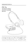
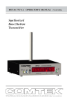
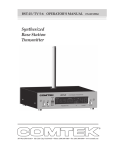
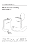
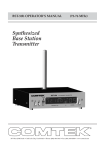
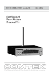
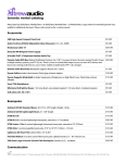
OPERATOR’S MANUAL
(76-88 MHz)
PR-216 / TV 5-6
High Performance
Personal Receiver
357 West 2700 South • Salt Lake City, Utah 84115 • Phone: (800) 496-3463 • Fax: (801) 484-6906 • http://www.comtek.com
INTRODUCTION
PR-216 / TV 5-6
High Performance
Personal Receiver
T
he PR-216/TV 5-6 is a professional
quality, personal monitor receiver
designed to meet the high demands of
the TV, motion picture production, and
entertainment industries.
In the motion picture industry, this
receiver is used by directors and
dignitaries for remote program
monitoring, as well as for talent cueing
and monitoring for boom-operators
and crew members. It is used in TV
production studios and ENG trucks for
director IFB, talent cueing and camera
crews.
The PR-216/TV 5-6 is our most
advanced, high fidelity, personal
monitor receiver incorporating both
advanced digital and analog
technologies. This receiver offers
superior audio performance with
the convenience of synthesized
frequency agility to accommodate
adverse multi-channel operation.
Page 1
PR-216 / TV 5-6 CONTROLS
n AUDIO OUTPUT JACK: This stereo 3.5 mm audio output jack accommodates
any low impedance headphone — either stereo or mono; also, charging input for
rechargeable battery, and auxiliary power input.
o VOLUME CONTROL: This control has 50 dB of range to adjust the audio
output for a comfortable listening level (clockwise for maximum level).
p POWER / RECEIVER STATUS INDICATOR:
The LED test indicator displays three functions:
1. The indicator will illuminate continuously
when unit is “ON” and NO signal is being
received.
2. A steady slow flash indicates the receiver
is receiving a signal on the tuned channel.
3. A rapid flash of the LED indicator and a
subtle beeping signal indicates a low battery.
q ON / OFF SWITCH: This switch turns the
receiver on and off.
r TV 5 OR 6 SWITCH: This switch
determines the band of the receiver.
Set to the left for TV 5 band
(76 MHz-82 MHz). Set to the
right for TV 6 band
(82 MHz-88 MHz).
s CHANNEL SWITCHES:
These rotary switches select the
channel. Channel must be the
same as transmitter’s channel.
(See page 6 for frequency selection chart.)
t BATTERY COMPARTMENT: The battery
compartment features a hinged battery cover and
an alignment system that ensures proper battery
polarity. Battery installation and removal is facilitated by
simply manipulating the rear of the battery.
Page 2
Battery
Cover Latch
PR-216 / TV 5-6 OPERATING INSTRUCTIONS
Setup
a. Check to ensure that the PR-216 receiver’s radio frequency channel is the
same as the associated COMTEK transmitter’s channel.
(Channels are indicated by the rotary switches on the back of the receiver. See page 4.)
b. Open the battery cover on the receiver (see page 8) and insert a new nine
volt alkaline battery (Eveready E522 or equivalent). This type of battery will
offer up to 30 hours of operation. (Replace the battery before every use if the
demand for fail-safe operation outweighs battery cost. The use of carbon batteries is
not recommended.)
NOTE: If a rechargeable battery is to be used, ensure that the
battery has a full charge before use. (See page 9 for battery
charger instructions.)
c. Connect the headphone to the receiver by inserting the headphone plug
into the receptacle on the top of the receiver. The receiver is operating when
the receiver power switch is turned on and the battery status on indicator
illuminates.
NOTE: The headphone cord also functions as part of the
receiver’s antenna system. For optimum performance, this cord
should be fully extended. Coiling or bunching the headphone
cord may reduce the range of the receiver. Also, coil-cord
type headphone cords are not recommended. The receiver
should be carried by the snap-on belt clip (included) or in a
pocket or belt-clip pouch.
d. Set the audio output level control to a comfortable listening volume. This
control is turned clockwise for maximum output level.
Page 3
PR-216 / TV 5-6 OPERATING INSTRUCTIONS
Frequency Selection (TV channels 5 and 6)
The PR-216 personal receiver has the ability to operate on one of 112 preset
channels between 76.200 MHz and 87.4 MHz (TV channel 5 and TV channel 6).
Channels are designated by both frequency and channel
number. Channels which operate in the TV 5
spectrum are prefixed with a 5 (5-50 is 81.100 MHz).
Channels operating in the TV 6 spectrum are prefixed
with a 6 (6-50 is 87.100 MHz). This channel rastering
makes it easy to determine which TV band you are
operating on. If you are using this system in an area
which does not have a TV station operating on channel 5,
you can use the channels in the TV 5 range. If the area does not
have a station on TV 6, you can operate on one of the TV 6 channels.
(NOTE: It is unlawful to operate a transmitter in a band that is already
occupied by a TV station.) After you have determined the channel on
which you are going to operate, position the TV band switch on the back of the
receiver to indicate the TV band you wish to use. Position the two rotary switches
to indicate the channel. The left rotary switch is for tens and the right rotary switch
is for ones. To select channel 6-17 (83.80 MHz), position the TV band switch to the
right, indicating use of the TV 6 band. Position the left rotary switch to point to 1,
and position the right rotary switch to point to 7. Refer to frequency charts on
pages 5 and 6 for preset selectable frequencies.
Multiple Channel Operation
Simultaneous operation of more than two channels
TANT
IMPOR
requires frequency coordination to avoid intermodulation
interference. This interference could result in poor or
unusable performance. When multiple transmitters are broadcasting, the RF
signals will “mix” together generating additional signals. If these
product frequencies are too close to a frequency which you are using,
you will experience this type of interference. This condition is common to
all radio receivers to some extent. This interference produces whistle
and whine type sounds and/or reductions of range. To avoid this type
of interference, you should select frequencies from one of the standard
groups (see frequency group charts on page 5), or you can use COMTEK’s
frequency selection guide software to determine appropriate frequencies.
Contact COMTEK to obtain a free copy of the frequency selection software
or download it off the web at www.comtek.com/software.htm.
Page 4
PR-216
PR-216
TV CHANNEL 5
FREQUENCY CHART
TV CHANNEL 6
FREQUENCY CHART
CHANNEL
5-1
5-2
5-3
5-4
5-5
5-6
5-7
5-8
5-9
5-10
5-11
5-12
5-13
5-14
5-15
5-16
5-17
5-18
5-19
5-20
5-21
5-22
5-23
5-24
5-25
5-26
5-27
5-28
5-29
5-30
5-31
5-32
5-33
5-34
5-35
5-36
5-37
5-38
5-39
5-40
5-41
5-42
5-43
5-44
5-45
5-46
5-47
5-48
5-49
5-50
5-51
5-52
5-53
5-54
5-55
5-56
5-57
5-58
5-59
FREQUENCY
76.200
76.300
76.400
76.500
76.600
76.700
76.800
76.900
77.000
77.100
77.200
77.300
77.400
77.500
77.600
77.700
77.800
77.900
78.000
78.100
78.200
78.300
78.400
78.500
78.600
78.700
78.800
78.900
79.000
79.100
79.200
79.300
79.400
79.500
79.600
79.700
79.800
79.900
80.000
80.100
80.200
80.300
80.400
80.500
80.600
80.700
80.800
80.900
81.000
81.100
81.200
81.300
81.400
81.500
81.600
81.700
81.800
81.900
82.000
MHz
MHz
MHz
MHz
MHz
MHz
MHz
MHz
MHz
MHz
MHz
MHz
MHz
MHz
MHz
MHz
MHz
MHz
MHz
MHz
MHz
MHz
MHz
MHz
MHz
MHz
MHz
MHz
MHz
MHz
MHz
MHz
MHz
MHz
MHz
MHz
MHz
MHz
MHz
MHz
MHz
MHz
MHz
MHz
MHz
MHz
MHz
MHz
MHz
MHz
MHz
MHz
MHz
MHz
MHz
MHz
MHz
MHz
MHz
Page 5
CHANNEL
FREQUENCY
6-0
6-1
6-2
6-3
6-4
6-5
6-6
6-7
6-8
6-9
6-10
6-11
6-12
6-13
6-14
6-15
6-16
6-17
6-18
6-19
6-20
6-21
6-22
6-23
6-24
6-25
6-26
6-27
6-28
6-29
6-30
6-31
6-32
6-33
6-34
6-35
6-36
6-37
6-38
6-39
6-40
6-41
6-42
6-43
6-44
6-45
6-46
6-47
6-48
6-49
6-50
6-51
6-52
6-53
82.100 MHz
82.200 MHz
82.300 MHz
82.400 MHz
82.500 MHz
82.600 MHz
82.700 MHz
82.800 MHz
82.900 MHz
83.000 MHz
83.100 MHz
83.200 MHz
83.300 MHz
83.400 MHz
83.500 MHz
83.600 MHz
83.700 MHz
83.800 MHz
83.900 MHz
84.000 MHz
84.100 MHz
84.200 MHz
84.300 MHz
84.400 MHz
84.500 MHz
84.600 MHz
84.700 MHz
84.800 MHz
84.900 MHz
85.000 MHz
85.100 MHz
85.200 MHz
85.300 MHz
85.400 MHz
85.500 MHz
85.600 MHz
85.700 MHz
85.800 MHz
85.900 MHz
86.000 MHz
86.100 MHz
86.200 MHz
86.300 MHz
86.400 MHz
86.500 MHz
86.600 MHz
86.700 MHz
86.800 MHz
86.900 MHz
87.000 MHz
87.100 MHz
87.200 MHz
87.300 MHz
87.400 MHz
PR-216
PR-216
TV CHANNEL 5
FREQUENCY GROUPS
TV CHANNEL 6
FREQUENCY GROUPS
GROUP ONE
GROUP ONE
CHANNEL
FREQUENCY
CHANNEL
5-3
5-6
5-10
5-15
5-21
5-34
5-42
5-56
74.400 MHz
76.700 MHz
77.100 MHz
77.600 MHz
78.200 MHz
79.500 MHz
80.300 MHz
81.700 MHz
6-4
6-7
6-9
6-13
6-20
6-30
6-38
6-50
GROUP TWO
CHANNEL
5-5
5-7
5-13
5-33
5-38
5-47
5-54
5-57
CHANNEL
6-2
6-5
6-28
6-34
6-42
6-44
6-49
6-53
MHz
MHz
MHz
MHz
MHz
MHz
MHz
MHz
GROUP THREE
CHANNEL
5-2
5-8
5-11
5-16
5-18
5-29
5-41
5-58
MHz
MHz
MHz
MHz
MHz
MHz
MHz
MHz
FREQUENCY
82.300
82.600
84.900
85.500
86.300
86.500
87.000
87.400
MHz
MHz
MHz
MHz
MHz
MHz
MHz
MHz
GROUP THREE
CHANNEL
FREQUENCY
76.300
76.900
77.200
77.700
77.900
79.000
80.200
81.900
82.500
82.800
83.000
83.400
84.100
85.100
85.900
87.100
GROUP TWO
FREQUENCY
76.600
76.800
77.400
79.400
79.900
80.800
81.500
81.800
FREQUENCY
6-1
6-3
6-6
6-10
6-16
6-24
6-36
6-52
MHz
MHz
MHz
MHz
MHz
MHz
MHz
MHz
Page 6
FREQUENCY
82.200
82.400
82.700
83.100
83.700
84.500
85.700
87.300
MHz
MHz
MHz
MHz
MHz
MHz
MHz
MHz
PR-216 / TV 5-6 OPERATING INSTRUCTIONS
Monitoring Capabilities
Because each monitoring application requires a
different headphone or transducer to best
satisfy each listening need, the PR-216 can
source a strong audio signal (+16 dBu) to
either stereo or mono headphones with
an impedance as low as 16 ohm.
A hearing-aid type button receiver may
be used with impedances as high as
2 k ohm and still produce a strong
audio signal.
The PR-216 is ideal for use with the
COMTEK NTC-102 neckloop
transductor and wireless IR-230
miniature universal-fit ear canal
inductor receiver or hearing aids
having a “T” switch.
Can be used with consumer or
professional headphones.
Can be used with
hearing aid button
receiver for assistive
listening or acoustic
ear tube for IFB
application.
Can be used to
drive neckloop for
use with IR-230
inductor receiver or
hearing aids.
Page 7
PR-216 / TV 5-6 OPERATING INSTRUCTIONS
Low Battery Indicator
The LED on the receiver is a multi-function indicator which includes low
battery detection. When the receiver is first turned on, the indicator will
illuminate continuously indicating that the unit is “ON” and NO signal is
being received. When the receiver is receiving a signal on the tuned
channel, the LED will show a steady slow
flash indicating reception. A rapid flash
on the LED indicator and a subtle beeping
signal through the headphone indicates
a low battery. Replace battery as soon as
possible with a new alkaline battery or
charge the rechargeable battery, as
performance of the receiver will be
Battery indicator LED
unpredictable and may vary from audio
distortion to complete failure to operate.
Battery Removal / Replacement
Pull back battery door latch and allow
battery cover door to spring open. To
remove battery, simply manipulate the
bottom of battery out of the
compartment and remove.
To insert battery, face
battery with negative
terminal in line with large hole in
battery compartment, press battery
into compartment and close battery door until
it snaps shut. Note: It is not possible to put
battery in backwards.
Page 8
PR-216 / TV 5-6 OPERATING INSTRUCTIONS
Battery Charging
1. Make sure that a seven cell 9 volt Ni-MH rechargeable
battery is used with a minimum of 150 mAh capacity.
(Alkaline batteries must not be charged.)
TANT
IMPOR
2. Make sure the PR-216 is turned OFF.
3. Note that the red charging indicator on the charger is ON when the PR-216
is plugged into the charger through the audio output jack.
4. When using the NBC 9-2C charger allow the battery to charge for 12 hours
for a full charge. Unit must then be unplugged. When using the
NBC 9-3-1 digital fast charger the charger will automatically end the
charge cycle and the red LED will change to green. With this charger
the unit may be left in the charger until the unit is used.
5. Periodically open the battery compartment on stored COMTEK units to
check for battery leakage. If a battery is leaking, it must be discarded,
and the battery compartment must be cleaned or returned to COMTEK’s
service department for repairs.
NBC 9-2C
12-hour charger
NBC 9-3-1
digital fast charger
Page 9
PR-216 / TV 5-6 SNAP ON BELT CLIP
STEP 2:
Belt clip installation
Rotate belt clip down onto case.
Apply pressure on both sides of
clip, snapping clip retainers into
slots.
Clip retainer
STEP 1:
Hook belt clip
retaining lip over
front case ridge.
Retainer slot
Belt clip removal indent
Belt clip removal
Flex out and pull down
with your thumb or twist
out with a large coin
(quarter) to unsnap belt
clip from case.
Page 10
PR-216 / TV 5-6 OPTIONAL ACCESSORIES
Optional Accessories
1. NBC 9-2C Dual 12-hour 9V only battery charger
2. NH9-150 Rechargeable Ni-MH battery
3. P1 Universal pouch
4. BC-216 Snap-on belt clip
(supplied with PR-216)
5. ET-4 SM-N Button receiver with acoustic ear tube
6. LS-3 High efficiency headphones
7. SM-N Button receiver earphone assembly
8. NTC-102 Neckloop transductor
(for use with inductor receiver IR230)
9. NBC 9-3-1 Digital single fast charger
10. NBC 9-3-12 Digital 12-station fast charger
Page 11
PR-216 / TV 5-6 SPECIFICATIONS
Audio Output:
Headset output +16 dBu
(low impedance)
RF Sensitivity:RF Sensitivity:
0.3 µV for 12 dB SINAD
Connector:
3.5 mm stereo/mono input used for:
• Headphone cord antenna to receiver
• Audio output to headphone
• Battery charger input
• Auxiliary power input
Indicators:
Three function LED
• Power
• Battery status
• R.F. signal ON and OFF
Adjacent Channel Rejection:
65 dB 50 kHz off channel
Spurious Rejection:
60 dB (image excluded)
Ultimate Quieting:
Better than 95 dB
Deviation Acceptance:
Up to 10 kHz
Antenna:
Integral with output cable
(no external antenna)
Controls:
• Power On/Off switch
• Volume control (50 dB range)
99-position rotary channel
• selector switches
Current Drain:
15 mA nominal
Power Requirements:
9 volt alkaline battery,
Eveready 522 or equivalent
or 9 volt Ni-MH rechargeable
Audio Frequency Response:
80 Hz to 12 kHz ±3 dB
Harmonic Distortion:
Less than 1% (1 kHz tone 5 kHz
deviation)
FCC Compliance:
Complies with Part 15
of FCC rules
Operating Radio Frequency:
• 76 to 88 MHz
• Frequency synthesized
Dimensions:
1 1/16" x 2 1/2" x 3 1/4"
(27 mm x 57 mm x 83 mm)
Frequency Stability:
0.002% frequency synthesized
crystal controlled
NOTE: Specifications subject to
change without notice
Page 12
357 West 2700 South • Salt Lake City, Utah 84115 • Phone: (800) 496-3463 • Fax: (801) 484-6906 • http://www.comtek.com