1
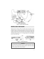
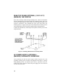
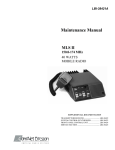
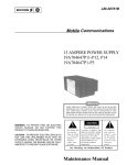
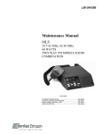
LBI-31694C Installation Manual MLS II Mobile Radio TABLE OF CONTENTS UNPACKING AND CHECKING EQUIPMENT ..........................3 PLANNING THE INSTALLATION.............................................3 INSTALLATION EQUIPMENT ..................................................4 RADIOS INSTALLED IN VEHICLES POWERED BY LIQUEFIED (LP) GAS ..............................................................5 RUNNING CABLES ..................................................................5 POWER CABLE ..............................................................................5 IGNITION SWITCH CONTROL.................................................6 INSTALLING THE RADIO ........................................................7 MOBILE MICROPHONE .................................................................8 DESK MICROPHONES (OPTIONAL) (OBSOLETE) ......................8 HOOKSWITCH ...............................................................................9 EXTERNAL SPEAKER (OPTIONAL) (OBSOLETE) .......................9 DESK TOP STAND (OPTIONAL) (OBSOLETE) ..........................10 AC POWER SUPPLY (OPTIONAL) ..............................................10 ANTENNA (OPTIONAL)................................................................11 PLACING THE TWO-WAY RADIO IN OPERATION ....................11 This manual is published by Com-Net Ericsson Critical Radio Systems, Inc., without any warranty. Improvements and changes to this manual necessitated by typographical errors, inaccuracies of current information, or improvements to programs and/or equipment, may be made by Com-Net Ericsson Critical Radio Systems, Inc., at any time and without notice. Such changes will be incorporated into new editions of this manual. No part of this manual may be reproduced or transmitted in any form or by any means, electronic or mechanical, including photocopying and recording, for any purpose, without the express written permission of Com-Net Ericsson Critical Radio Systems, Inc. Copyright © 1987-2001 Com-Net Ericsson Critical Radio Systems, Inc. All rights reserved. 2 UNPACKING AND CHECKING EQUIPMENT Carefully unpack the radio. It is recommended that you identify the items ordered and check them off in the boxes below before discarding the packing material. If any damage has occurred to the equipment during shipment, file a claim with the carrier immediately. • Mobile Radio 19A704991 • Power Control Cable JRC/6ZCFD00166 • Microphone 19B801398Pl • Antenna, Cable, and RF Connector (Optional) • Microphone Hookswitch JRC/MPBP02430 • External Speaker (Optional) 19C850550G6 (OBSOLETE) • Mounting Hardware Kit JRC/MPXP01777 • Mounting Bracket JRC/MPBX15589 • Desk Top Stand (Optional) 19A138051G8 (OBSOLETE) It is suggested that you take advantage of the experience of one of the many authorized Service Centers located throughout the United States by having them install your two-way radio and make the final adjustments. WARNING! INTERFERENCE WITH VEHICULAR ELECTRONICS – Electronic fuel injection systems, electronic anti-skid braking systems, electronic cruise control systems, etc., are typical of the types of electronic devices which may be prone to malfunction due to lack of protection from radio frequency energy present when transmitting. If the vehicle contains such equipment, consult the dealer for the make of the vehicle and enlist his aid in determining if such electronic circuits will perform normally when the radio is transmitting. PLANNING THE INSTALLATION The accompanying illustrations should help you plan your installation. Before starting, plan your installation carefully so that it will be: • Safe for the operator and passengers in the vehicle, • Convenient for the operator to use, • Neat, 3 • Easy for the serviceman to service, • Out of the way of auto mechanics, • Out of the way of passengers, and • Protected from damage by water. Figure 1 – Typical Console/Hump or Dash Mount INSTALLATION EQUIPMENT The equipment required for installing the radio includes: • An electric drill for drilling mounting holes • Drills and circle cutters (see sizes below) • A soldering iron for the antenna cable Phillips and PoziDriv screwdrivers and a 7mm hex head driver for mounting screws DRILL SIZES • • No. 27 (9/64-inch) Drill for No. 10 Self-Tapping Screws • No. 31 (1/8 inch) Drill for No. 8 Self-Tapping Screws • No. 36 (7/64 inch) for No. 6 Self-Tapping Screws • 3/4-Inch Punch or Holesaw for 800 MHz Antenna (optional) • 5/8-Inch Punch or Holesaw for rubber grommet POZIDRIV Trademark of Phillips International Co. 4 RADIOS INSTALLED IN VEHICLES POWERED BY LIQUEFIED (LP) GAS WARNING Radio installations in vehicles powered by liquefied petroleum gas must conform to the following requirements. Radio installations in vehicles powered by liquefied petroleum gas with the LPgas container in the trunk or other sealed-off space within the interior of the vehicle must conform to the National Fire Protection Association Standard NFPA 58 that requires that: • The space containing radio equipment shall be isolated by a seal from the space containing the LP-gas container and its fittings. • Outside filling connections shall be used for the LP-gas container. • The LP-gas container space shall be vented to the outside of the vehicle. RUNNING CABLES To assure the feasibility of the cable routings you plan to use, it is suggested that you run the cables before mounting the radio. Be sure to leave some slack in each cable going to the radio so that the radio may be pulled out for servicing with the power applied. Try to route the cables away from locations where they will be exposed to heat (exhaust pipes, mufflers, tailpipes, etc.), battery acid, sharp edges, or mechanical damage or where they will be a nuisance to automobile mechanics, the driver, or passengers. Keep wiring away from electronic computer modules, other electronic modules, and ignition circuits to help prevent interference to these components and radio equipment. In addition, try to utilize existing holes in the firewall and trunk wall and the channels above or beneath the doors. You may also use the channels through door and window columns, where they are convenient for running cables, unless you plan to install rigid or flexible conduit in which to run the cables. POWER CABLE The Power Cable is supplied for negative ground systems only. It consists of a fused red lead, a black lead, and a fused yellow lead (ignition switch control). To install the Power Cable, run the red and black leads to the vehicle battery and the yellow lead to the ignition switch. If an existing hole is not conveniently located on the driver’s side firewall for the passage of the Power Cable through 5 the firewall, drill a 5/8 inch hole and insert the rubber grommet provided. If the battery is located on the passenger side of the vehicle, the battery leads should cross the vehicle in front of the engine. All attempts should be made to maintain as much distance as possible between the radio power lead and any vehicle electronic modules and wiring. Be sure to keep these leads mounted so they cannot snag on any moving part of the engine. Connect the red lead to the positive (+) battery terminal and the black lead to the negative (-) battery terminal. Always locate the fuse as close to the battery as possible. Coil up the surplus cable and secure it out of the way with the retaining strap provided. Be sure to leave some slack in the cables going to the radio so that it may be pulled out for servicing with the power applied. IGNITION SWITCH CONTROL With ignition switch control, the transmitter and receiver operate only with ignition switch in the Accessory or On position. Connect the yellow fused lead to the ignition switch terminal. Then remove the jumper between A+ and the ignition lead on the system power cable plug (see Figure 2). If the ignition switch control is not used, cut and tape the end of the yellow lead to prevent shorts and do not cut the jumper between A+ and the ignition lead on the system power cable. NOTE With some accessory points, the voltage only drops when the ignition switch is in the START position. A connection point should be used where the voltage is completely off when the ignition switch is in the START position. If electrical noise is excessive at the accessory block, install alternator noise filter option MLPDlA. CAUTION Certain problems may be encountered when accessory equipment is connected to the ignition or accessory lines of the vehicle, where these lines may have large filter capacitors or a leakage path is present. If the radio does not turn off within a reasonable amount of time after the ignition is turned off, first try a different accessory or ignition sense pick up point in the vehicle. Many vehicles have more than one circuit that is switched by the ignition switch, and one may be available that does not have large filter capacitors or a leakage path present. If a different pickup point cannot be found, try adding a 470-ohm, 1-watt resistor from the ignition sense pickup point to ground. This will discharge the capacitor(s) or reduce the leakage voltage to a low value. Current drain through this resistor will be minimal (less than 0.03A) when the ignition is switched on. 6 Figure 2 - System Cable Interconnect INSTALLING THE RADIO Mount the radio so that the controls are within reach of the operator. Use the mounting bracket as a template to locate the holes and mount the radio as shown in Figure 4. (Figure 3 provides dimensional data.) Be sure to leave enough room at the rear of the radio for cable connections. Before attaching the radio in the mounting brackets, connect the antenna plug, systems plug, and microphone. Torque radio mounting bolts to 1.58 - 2.14 Newton Meters (14-19 inch pounds). Do not exceed torque rating. Figure 3 - Mounting Dimensions WARNING For passenger safety, mount the radio securely so that the unit will not break loose in the event of a collision. This is especially important in station wagons, vans, and similar type installations where a loose radio could be extremely dangerous to the vehicle occupants. 7 Figure 4 - Typical Mounting Bracket Installation CAUTION Be careful to avoid damaging some vital part (fuel tank, transmission housing, etc.) of the vehicle when drilling mounting holes. Always check to see how far the mounting screws will extend below the mounting surface before installing. MOBILE MICROPHONE Mount the microphone where it will be within easy reach of the operator, but will not interfere with safe operation of the vehicle. After the microphone bracket is mounted, connect the microphone plug into the microphone jack on the rear of the radio and connect the strain relief to the terminal, shown in Figure 5. DESK MICROPHONES (OPTIONAL) (OBSOLETE) Desk microphones are available for use with the MLS II radios (options MLMC1L or MLMC1R). 8 Figure 5 - Microphone HOOKSWITCH After determining the mounting location for the microphone hookswitch, mount the hookswitch as indicated in Figure 6. For added strength, a plate is provided to go on the back side of the mounting surface. After mounting the hookswitch, connect one wire to pin 7 of the microphone plug and one wire to ground as shown in Figure 6. Figure 6 - Hookswitch Mounting EXTERNAL SPEAKER (OPTIONAL) (OBSOLETE) The speaker should be mounted where it will direct sound to the operator, but not interfere with his vision or provide a hazard to passengers in case of an accident. The speaker may be mounted on the lower edge of the instrument panel, on the firewall, above the windshield in some trucks, or behind the built in speaker grille in some vehicles. Use the mounting bracket as a template for locating the mounting holes and mount the speaker bracket as shown in Figure 7. Connect external speaker wires to microphone plug J701 pins 1 and 6. Figure 7 - Speaker Mounting 9 DESK TOP STAND (OPTIONAL) (OBSOLETE) (MLMA1K) 19A138051G8 Place radio in desktop stand and align mounting holes. Insert the lockwashers and four M4x8mm hex head bolts through the mounting bracket and secure radio. Before tightening bolts, position radio to the desired upward angle for the operator’s convenience. After mounting the radio, press radio down onto mounting surface to engage suction cups. The desktop stand is normally used in station applications and is used with the standard mobile mounting bracket. Complete the installation by connecting the microphones, antenna, power cable, and ground cable. Figure 8 - Mounting Mobile Bracket to Desktop Stand AC POWER SUPPLY (OPTIONAL) (MLPS5K) 19A704647P2 120/240 VAC After positioning the radio and power supply, install the ground wire. This grounding will help protect operators and equipment from injury or damage during lightning storms. An eight-foot power cable is provided to allow for remote power supply location. Connect the power supply jack to the radio and AC line cord to AC source. 10 ANTENNA (OPTIONAL) (MLAN1A) HB/UHF 19B209568P1 (MLAN1C) LOW BAND 7491074P1 Installation instructions for the antenna are packaged with the antenna. The antenna must be installed in accordance with good engineering practice for optimum results. A permanent mount type of antenna should be located in the center of the roof or the center of rear deck. Glass mounted antennas should be kept as high as possible in the center of the rear window. Some states have laws restricting vision-obstructing items from the windows. Be aware of local laws before installing glass mount antennas. Try to route the cable away from locations where it will be exposed to heat, sharp edges, or mechanical damage, and where it will be out of the way of the driver, passengers, or vehicles mechanics. Wherever possible, existing holes in the trunk wall, and the channels above or beneath doors and window columns should be utilized. Avoid routing the antenna cable near any electronic modules or along side any vehicle wiring. Connect the antenna cable to the type N connector on the radio. CAUTION In station applications, the radio will not operate properly with the antenna mounted directly on the back of the radio. Always mount the antenna at least five feet from the radio. PLACING THE TWO-WAY RADIO IN OPERATION After completing the installation of the two-way radio, the following final operations should be performed: FOR U.S. INSTALLATIONS Have a certified electronics technician make the final adjustments. Instructions for making these adjustments are included in the maintenance manual for the radio. These include: Transmitter: Measure forward and reflected power and adjust antenna length for optimum ratio. Set the transmitter to rated power output. Measure the frequency and modulation and record these measurements for future reference. Vehicle: Check to see if any electrical noise suppression is needed. 11 Complete the Registration Card provided, and return it to an authorized representative or distributor. Give the Operator’s Manual to the person who is going to operate the radio or place the manual in the vehicle FOR INTERNATIONAL INSTALLATIONS Maintain records consistent with those applicable under the regulations of the country where the equipment is installed. Complete the Registration Card provided, and return it to an authorized representative or distributor. 12 NOTES 13 NOTES 14 NOTES 15 Com-Net Ericsson Critical Radio Systems, Inc. P.O. Box 2000 Lynchburg, Virginia 24501 1-800-528-7711 (Outside USA, 804-385-2400) www.com-netericsson.com Printed in U.S.A.