1
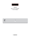
Ayre VX-5
Owner’s Manual
Stereo Power Amplifier
Table of
Contents
Welcome to
Ayre . . . . . . . . . . . . . . . . . . . . . . . 2
Connections and
Installation . . . . . . . . . . . . . . . . . . . . 3
Controls and
Operation . . . . . . . . . . . . . . . . . . . . . 7
Optimization and
Customization . . . . . . . . . . . . . . . . . . 9
Numbers and
Specifications . . . . . . . . . . . . . . . . . . 13
In Case of
Trouble . . . . . . . . . . . . . . . . . . . . . 14
Statement of
Warranty . . . . . . . . . . . . . . . . . . . . 17
A Place for
Notes . . . . . . . . . . . . . . . . . . . . . . 20
Welcome to
Ayre
To our North American
customers, please be sure to
mail your warranty
registration card and
photocopy of your original
sales receipt within 30 days
in order to extend the
warranty to five years.
Your Ayre VX-5 offers a significant advance in the
musical performance of high-fidelity equipment.
The warmth and immediacy of a live performance
are apparent from the first listening. The
combination of superb resolution and a natural,
relaxed quality will draw you into the music, time
and time again.
This level of performance has been implemented
using the highest level of workmanship and
materials. You can be assured that the Ayre VX-5
will provide you a lifetime of musical enjoyment.
2
Connections and
Installation
The Ayre VX-5 is easy to use. The following
guidelines will ensure that the installation goes
smoothly.
Location
Do not stack the Ayre VX-5
directly with other
components, as this may
restrict the air flow or induce
hum into the audio circuitry.
A good location for your power amplifier is in an
open-backed cabinet or on a shelf. The VX-5
produces a moderate amount of heat during
operation. Be sure to provide at least three inches
(75 mm) of air space above the amplifier.
An adequate supply of air flow will
avoid overheating the amplifier.
.Inputs
When you have a choice, a
balanced connection will offer
slightly higher sound quality
than a single-ended
connection.
The Ayre VX-5 offers one pair of balanced inputs
and one pair of single-ended inputs. Balanced
connections are made via three-pin XLR connectors,
while single-ended connections are made with RCA
connectors.
3
Above each channel’s input connectors is a small
toggle switch. Be sure to set the switch to the
correct setting for the input you have chose to use.
The input configuration switch does not protrude
far from the rear panel. This is to avoid
accidentally setting it to the wrong position. If
necessary use a toothpick (or similar object) to
select the switch position.
Loudspeaker Outputs
The heavy-duty output
terminals of the Ayre VX-5
work best with speaker cables
equipped with spade lugs.
The Ayre VX-5 drives the loudspeakers with
balanced outputs. Since none of the output
terminals are grounded, connecting any of them to
ground may result in damage to the amplifier.
Do not connect the loudspeaker
outputs to any speaker switch-box,
accessory, or test equipment that has a
common ground connection.
Two sets of speaker terminals are provided for
each channel. This allows for easier use of
multi-wired (e.g., bi-wired) connections. There is
no difference between the pairs of outputs.
4
AC Power
The VX-5 may be plugged directly into an
unswitched wall outlet. Although proprietary RFI
(radio-frequency interference) filtering is built into
the amplifier, in some situations an AC power-line
filter (such as those offered by Ayre) may provide
additional sonic benefits.
AyreLink Ports
The AyreLink communication system provides a
convenient way to control your audio system. There
are two AyreLink ports on the rear panel of the
VX-5 stereo amplifier. Each port has four contacts
and contains both an input and an output. Both
ports function identically and may be used
interchangeably.
AyreLink connections are made with commonly
available two-line telephone line cords using
modular (RJ-11) connectors. (These are the cords
that connect the telephone set to the wall in many
countries.) They are readily available in different
lengths and various colors at most electronics stores.
Be sure to use two-line telephone
cords to make AyreLink connections.
These can be identified by the four
gold contacts on each connector.
Single-line cords with only two gold
contacts will not function in this
application.
5
The linked components may be
joined in any convenient
order.
The linked components should be connected in
daisy-chain fashion, connecting each component to
another until all of the linked components have
been connected.
When connecting the linked
components to form a chain, be careful
not to connect the two ends of the
chain. Closing the chain to form a loop
will cause the AyreLink system not to
function.
Break-In
100 to 500 hours of music
played through the system will
ensure full break-in.
Due to the manufacturing processes used for the
wires, capacitors, and circuit board materials, a
break-in period is necessary for the amplifier to
reach its full sonic potential.
Each input uses a different physical path on the
input circuit board. Therefore a separate break-in
period is required for each input.
6
Controls and
Operation
In addition to the normal controls on the front
panel, the Ayre VX-5 may also be controlled via
other AyreLink-equipped components.
On/Off (1/0)
The main power switch for the VX-5 is a rocker at
the top center of the rear panel. This switch
disconnects the unit completely from the AC power.
When the amplifier is turned “off” none of the
auxiliary functions (e.g., the AyreLink system
communication) are operable. After the unit is
turned on, it may take perhaps 30 minutes or so to
fully warm up and sound its best.
Mute/Low-Power Consumption
The front-panel button on the VX-5 serves two
functions—mute, and control of the low-power
consumption mode.
7
Mute
A short press of the front-panel button provides an
easy way to temporarily mute the output of the
VX-5. Pressing the button a second time restores
the output.
When the mute function is activated, the
front-panel LED will glow green.
Low-Power Consumption Mode
Press and hold the front-panel button for three
seconds to enter the low-power consumption mode.
The audio will shut off, yet the auxiliary functions
remain active. This mode is indicated by
illuminating the green LED ring in the button.
A long press of the front-panel button will place
all AyreLinked components in your system into
low-power consumption mode.
The warm-up time is minimized by applying power
to the audio circuitry. To reduce power
consumption when not listening to music, all bias
current is removed from the output stage.
8
Optimization and
Customization
The VX-5 power amplifier is configured from the
factory for flexible operation in most audio systems.
However, in certain installations it may be desirable
to change the factory default settings or create an
alternate control connection.
Display Brightness
Normally the brightness of the status LED is
controlled by other linked components connected to
the VX-5 via the AyreLink communications port.
However if there are no other AyreLink components
available, the brightness level may be set while the
unit is in the configuration mode.
To enter the configuration mode, turn the amplifier
“Off” with the rear-panel power switch for at least
one minute. Then press and hold the front-panel
button while switching the power back “On”. The
status LED will flash violet to indicate the amplifier
is in configuration mode.
The unit will remain in configuration mode for ten
seconds. During that time, pressing the front-panel
9
button will change the default setting for the
brightness of the status LED as noted below:
One press – Low brightness
Two presses – Medium brightness
Three presses – High brightness
After the ten-second configuration period has
elapsed, the status LED will revert to green (“Mute”
mode).
If no button presses are detected during the ten
second period, the unit will revert to the factory
default setting (high brightness).
Changes to the default settings will also be
transmitted via the AyreLink communication
system to other linked components.
Trigger Control
A trigger control allows one component to control
the low-power consumption mode of another
component. If there are no AyreLink source
components available to control the operation of the
VX-5 amplifier, it may be convenient to use the
trigger control from a source component.
The trigger signal from a source component will
directly control the VX-5 amplifier. The VX-5 can
then in turn control amplifiers linked by the
AyreLink communications system. Connect the
AyreLink ports of your components in a daisy-chain
fashion as described in the chapter “Connections and
Installation” with the VX-5 at one end of the chain.
10
The unused AyreLink port on the amplifier is then
used as a trigger input.
Rear view of VX-5 amplifier.
An adapter cable must be fabricated to connect the
trigger output of the control component to the
AyreLink port of the VX-5 amplifier. The easiest
way to do this is to remove the modular (RJ-11)
connector from one end of a two-line telephone line
cord. (This is the type of cord that connects the
telephone set to the wall. A two-line cord will have
four gold contacts on each connector.) Then attach
the connector appropriate for the component with
the trigger output. Please refer to the owner’s
manual of that source component for details.
The trigger voltage should be between
+5 and +12 volts DC for proper
operation. The current draw of the
trigger input on the AyreLink port is
less than 5 mA.
There are two signaling methods that may be used;
level and pulse. The VX-5 automatically senses
which type of trigger signal is being sent and
responds accordingly.
11
A positive-going pulse of greater than 250 msec is
treated as a level-sensitive trigger. Shorter pulses
are treated as a pulse-sensitive trigger. The
minimum detectable pulse length is 200 µsec.
During level-sensitive operation, applying a voltage
to the trigger input will set the amplifier to the
“Operate” mode. When the applied voltage drops to
zero, the unit reverts to the low-power consumption
mode.
In the pulse-sensitive mode, a positive-going pulse
will toggle the amplifier between the low-power
consumption and “Operate” states, duplicating the
action of the right-hand front-panel button when it
is held for three seconds.
The front-panel button remains operative when
the trigger input is used. Therefore, using the
front-panel button will put the amplifier out of
“sync” with the trigger control device. When
used with level-sensitive trigger operation, the
next trigger action will automatically restore
“sync”. However when using pulse-sensitive
trigger operation, “sync” can only be restored by
pressing the front-panel button a second time.
12
Numbers and
Specifications
Power Output
Input Impedance
XLR Input Polarity
Gain
175 watts per channel continuous into 8 ohms
350 watts per channel continuous into 4 ohms
1 MΩ – unbalanced inputs
2 MΩ – balanced inputs (1 MΩ per phase)
Pin 1 = Ground
Pin 2 = Non-inverting (Positive)
Pin 3 = Inverting (Negative)
26 dB
Frequency Response
DC - 250 kHz
Power Consumption
35 watts in low-current consumption mode
325 watts in operating mode, no signal
Dimensions
Weight
17-¼" W x 18-¾" D x 4-¾" H
44 cm x 48 cm x 12 cm
52 pounds
24 kg
13
In Case of
Trouble
The Ayre VX-5 provides comprehensive protection
for both your amplifier and loudspeakers, including
faults that may occur in your source components.
Overheating
If the unit is operated with insufficient ventilation,
the internal temperature may become too high,
triggering the thermal protection. In this case the
amplifier will mute, the bias current to the output
stage will be removed, the front-panel LED will
glow orange, and the front-panel mute/low-power
consumption button will be inoperative.
If connected to an AyreLink-equipped
preamplifier, a message indicating the amplifier
has overheated will be displayed.
If overheating occurs, be sure
to correct the cause before
continuing to use the
amplifier.
14
Once the unit has cooled, the LED ring in the
pushbutton will glow green, but the front-panel
LED will remain orange so that the cause of the
error is known. To restore the unit to the normal
operation mode, simply press the front-panel
button.
Rail Fuses
Eight internal power supply fuses protect both the
loudspeakers from excessive current and the
amplifier from short-circuits. If any of these fuses
blow, the amplifier will not operate and the
front-panel LED will flash red.
If connected to an AyreLink-equipped
preamplifier, a message indicating the amplifier
fuse has blown will be displayed.
The amplifier must be completely disconnected
from the AC power to replace the fuses.
Do not remove the amplifier cover.
Hazardous voltages may exist inside
the unit. Please refer fuse replacement
to a qualified service technician.
AC Line Voltage
If the AC line voltage drops below 85% of normal
(brown-out), the front-panel LED will glow violet
and the unit will not operate.
If connected to an AyreLink-equipped
preamplifier, a message indicating the AC line
voltage is too low will be displayed.
When the AC line voltage returns to normal, the
LED ring in the pushbutton will glow green, but
the front-panel LED will remain violet, so that the
cause of the error is known. Press the front-panel
button to return the unit to the operate mode.
15
DC Offset
The Ayre VX-5 incorporates a circuit to detect the
presence of DC at the output terminals which could
be harmful to the loudspeaker. In this situation, the
front-panel LED will glow red, the input will be
muted, the bias will be removed from the output
stage, and the amplifier will not operate.
If connected to an AyreLink-equipped
preamplifier, a message indicating the amplifier
has DC at the output will be displayed.
If the DC offset was coming from a faulty source
component, when the amplifier input mutes the
source of the fault will be removed. The LED ring in
the pushbutton will glow green, but the front-panel
LED will remain red, so that the cause of the error is
known. If the fault is internal to the unit, the LED
ring in the push-button will not glow green.
If the fault was due to a source component,
disconnect it from your system. Then press the
front-panel button to return the VX-5 to the
normal operate mode and select a different source
component. If the system operates properly in this
case, take the faulty source component to an
authorized dealer or service center.
If there are any unusual noises coming
from the loudspeaker, turn the
rear-panel AC power switch to “Off/0”
immediately. Please return the unit to
your authorized dealer or service
center.
16
Statement of
Warranty
North American Warranty
Your Ayre VX-5 power amplifier is warranted
against defects in materials and workmanship for a
period of ninety days from the date of original
purchase. This ninety-day coverage is automatic
upon acceptance of delivery and no registration is
required.
Additionally you have the option, at no cost, to
extend the warranty for a period of five years from
the date of purchase by returning the completed
Warranty Registration Card and a photocopy of
your original purchase receipt in the enclosed
postage-paid envelope to Ayre within thirty days of
product delivery. This optional warranty is only
available within the thirty-day registration period.
17
North American Warranty Statement
1. If any defects are found in the materials or
workmanship of this Ayre product within the
warranty period, the unit will be repaired or
replaced by Ayre Acoustics, Inc. (Ayre) or its
authorized agent.
2. Purchaser must return the product, packed in the
original shipping carton, freight prepaid to:
Ayre Acoustics, Inc.
2300-B Central Avenue
Boulder, Colorado 80301
or to Ayre’s authorized agent. The product must be
accompanied by a written description of the defect
and a photocopy of your original purchase receipt.
Ayre will not be responsible for any shipping
damage and strongly recommends the purchase of
shipping insurance. Ayre reserves the right to
inspect any product that is the subject of any
warranty claim prior to repairing or replacing it.
Final determination of warranty coverage lies solely
with Ayre.
Out-of-warranty claims will be billed for labor,
materials, return freight, and insurance as required.
Any product for which a warranty claim is accepted
will be returned to the purchaser and the cost of
shipping and insurance will be factory prepaid
within the boundaries of the USA. Units to be
shipped outside of the USA will be shipped freight
collect only.
18
4. Ayre strives to manufacture the finest possible
equipment, and therefore reserves the right to make
improvements on its products, without necessarily
assuming any obligation to retrofit such changes
upon its previously manufactured models.
5. The above warranty is the sole warranty given by
Ayre, and is in lieu of all other warranties. All
implied warranties, including warranties of
merchantability or fitness for any particular purpose
shall be strictly limited to the duration of the above
warranty. Ayre shall have no further obligation of
any kind, whether express or implied. Further, Ayre
shall in no event be obligated for any incidental or
consequential damages as a result of any defect or
any warranty claim, whether express or implied.
6. Ayre does not authorize any third party,
including any dealer or sales representative, to
assume any liability of Ayre or make any warranty
for Ayre. The unit must not have been altered or
improperly serviced. The serial number on the unit
must not have been altered or removed.
7. The remaining period of this warranty is only
transferable to subsequent purchasers if the product
is resold by an authorized Ayre dealer.
International Warranty
Warranty terms outside of North America may
vary. Please contact the authorized Ayre distributor
in your country of purchase for the terms of
warranty and also the service itself.
19
A Place for
Notes
20
Serial Number:
________________________________________
Purchase Date:
________________________________________
Dealer:
________________________________________
Salesperson:
________________________________________
Rev. 1.0
Ayre Acoustics, Inc.
2300-B Central Avenue
Boulder, Colorado 80301
www.ayre.com
+1-303-442-7300