Download Ayre Acoustics V-6x Stereo Amplifier User Manual
Transcript
Ayre V-6x
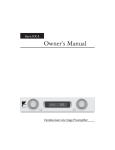
Owner’s Manual
A y r e
V-6x
Power Amplifier
Table of
Contents
Welcome to
Ayre . . . . . . . . . . . . . . . . . . . . . . . 2
Connections and
Installation . . . . . . . . . . . . . . . . . . . . 3
Controls and
Operation . . . . . . . . . . . . . . . . . . . . . 7
Numbers and
Specifications . . . . . . . . . . . . . . . . . . 10
In Case of
Trouble . . . . . . . . . . . . . . . . . . . . . 11
Statement of
Warranty . . . . . . . . . . . . . . . . . . . . 14
A Place for
Notes . . . . . . . . . . . . . . . . . . . . . . 17
Welcome to
Ayre
Please send in your warranty
registration card so we can
stay in contact with you.
Your Ayre V-6x offers a significant advance in the
musical performance of high-fidelity equipment.
The warmth and immediacy of a live performance
are apparent from the first listening. The
combination of superb resolution and a natural,
relaxed quality will draw you into the music, time
and time again.
This level of performance has been implemented
using the highest level of workmanship and
materials. You can be assured that the Ayre V-6x
will provide you a lifetime of musical enjoyment.
2
Connections and
Installation
The Ayre V-6x is easy to hook up and use. The
following guidelines will ensure that the installation
goes smoothly.
Location
Do not stack the Ayre V-6x
directly with other components,
as this may restrict the air
flow or induce hum into the
audio circuitry.
A good location for your power amplifier is on the
floor between your loudspeakers, or in an
open-backed cabinet, or on a shelf. The Ayre V-6x
produces a moderate amount of heat during
operation. Be sure to provide at least three inches
(75 mm) of air space above the amplifier.
It is important to maintain an adequate
supply of air flow to avoid overheating
the amplifier.
AC Power
The best sound quality is normally achieved when
the V-6x is plugged directly into an unswitched
wall outlet, without using any power strips or power
line conditioners.
3
Inputs
When you have a choice, a
balanced connection will
usually offer slightly higher
sound quality.
The power amplifier can be driven by a
surround-sound processor or preamplifier. There are
two sets of input connectors for each installed
channel of the Ayre V-6x. The RCA connectors
accept signals from unbalanced sources, while the
XLR connectors are for balanced sources.
Only one set of inputs
(balanced or unbalanced) may
be connected at a time.
A small toggle switch near the input connectors
selects either the balanced or unbalanced inputs.
Note that the input selector switch for one channel
will be in the “up” position, while the other
channel’s input selector switch will be in the
“down” position.
Using the incorrect position on
the input selector switches will
not harm the equipment, and
the amplifier may even seem to
operate normally. However,
some sonic degradation occurs
in this situation.
Selecting “Unbal” connects the inverting input to
ground through an isolation resistor. Therefore, the
incorrect setting of this switch forces a balanced
source to operate in unbalanced mode. Conversely, if
the selector is set to “Bal” while using an
unbalanced source, the unused inverting input is
susceptible to hum pick up and radio-frequency
interference.
Pass-Through Outputs
The pass-through output
connector is wired in parallel
with the input connector.
4
Each channel features a pass-through output,
supplied via an XLR connector. This allows
multiple channels to be driven with a single source
and is especially useful for subwoofers, passive bi- or
tri-amplification, or distributed sound systems.
Simply use a balanced cable to connect the
pass-through output of one channel to the XLR
V-6 Power Amplifier
Unbal
Input Sel
Bal
¡Attention! — Balanced Outputs
Do Not Connect Output Terminals to Ground
S.N.
Unbal
Pass-Through
Output
Input Sel
Bal
Unbal
Pass-Through
Output
Input Sel
Bal
Pass-Through
Output
Trigger In/Out
Fuse -
+ Fuse
Fuse -
+ Fuse
Fuse -
+ Fuse
Volts
50/60 Hertz
1800 W Max
Fuse +
- Fuse
Fuse +
- Fuse
Fuse +
- Fuse
Pass-Through
Output
Bal
Input Sel
Pass-Through
Output
Unbal
Bal
Input Sel
Pass-Through
Output
Unbal
A y r e
Bal
Input Sel
Unbal
Boulder, Colorado USA
input of another channel on the same amplifier, or of
another amplifier with true balanced inputs.
The pass-through output does
not convert unbalanced sources
to a true balanced signal.
If you wish to drive an unbalanced amplifier from
the pass-through outputs, you will need to use
XLR-to-RCA adapters. These should be configured
so that pin 1 of the XLR is connected to the shell of
the RCA connector, and pin 2 of the XLR is
connected to the center pin of the RCA connector.
Loudspeaker Outputs
The heavy-duty output
terminals of the Ayre V-6x
work best with speaker cables
using spade lugs.
The Ayre V-6x drives the loudspeakers with
balanced outputs. Since none of the output
terminals are grounded, connecting any of them to
ground may result in damage to the amplifier.
D o n o t c o n n e c t th e l o u d s p e a k e r
outputs to any speaker switch-box,
accessory, or test equipment that has a
common ground connection.
5
Controls and
Operation
The Ayre V-6x has a front panel control for normal
stand-alone operation. The amplifier may also be
controlled via a “trigger” input in a home-theater.
Power Switches
The master power switch on
the rear panel also
incorporates a circuit breaker.
There are two power switches on the Ayre V-6x.
The master power switch on the rear panel is
normally intended to be left on at all times. The
front-panel switch selects between the “Standby”
and “Operate” modes.
When the master power switch is first turned on,
the front panel indicator light will glow red for
approximately one second. During this time, the
unit is in “Warm-Up” mode and the front-panel
switch is inoperable.
Red = Warm-Up
Green = Standby
Blue = Operate
6
After the circuitry has stabilized, the indicator light
will change to green, indicating that the unit is in
“Standby” mode and is ready for operation. When
the listener presses the front-panel switch, the unit
is in “Operate” mode and the indicator light glows
blue.
In the green “Standby” mode the output stage is
turned off, while the input circuitry remains
powered. This allows the unit to warm up quickly
for optimal sonic performance, while reducing the
power consumption from 60 watts per installed
channel to 10 watts total.
Trigger Input
Use a 1/8" mini-phone plug
with a positive voltage of
between +5 and +12 VDC
at the tip to operate the trigger
input.
A trigger input is provided on the rear panel of the
V-6x to allow for remote switching between the
green “Standby” and blue “Operate” modes. The
two trigger input jacks are wired in parallel. Either
jack can act as an input or a pass-through output to
allow for “daisy-chaining” of multiple devices.
The unit is shipped from the factory in the
level-sensitive mode, which is compatible with most
equipment. During level-sensitive operation,
applying a voltage to the trigger input will force the
amplifier to the “Operate” mode. In this state, the
front panel switch is inoperative. When the applied
voltage drops to zero, the unit reverts to “Standby”
and the front panel switch may be used to manually
control the unit.
Some equipment instead utilizes pulses as a trigger
signal. The V-6x can also accommodate these units.
To change trigger modes, turn the rear panel switch
“Off” for about 30 seconds to discharge the internal
voltages. Then press and hold the front panel switch
while turning the rear panel switch “On”. The status
LED will rapidly flash red (about 10 Hz) to indicate
that the pulse-sensitive mode has been selected.
7
Repeating this procedure will revert the unit back
to the level-sensitive mode, as indicated by the
status LED slowly flashing red (about 1 Hz).
In the pulse-sensitive mode, a positive-going pulse
edge will toggle the amplifier between the
“Standby” and “Operate” states, duplicating the
action of the front-panel switch. In this mode the
front panel switch is always operative. However,
operating the unit with the front panel switch may
put the unit out of “synch” with the control device.
If this should occur, simply press the front panel
switch to restore “synch”.
Channel Configuration
Each channel of the V-6x is a self-contained module
(except for the power supply). If you wish to add
channels to your amplifier after purchase, additional
modules may easily be installed by your authorized
Ayre dealer.
The V-6x will hold a maximum of six channels.
There are three independent power supplies
installed. One power supply feeds the two left-hand
slots, another feeds the two center slots, and another
feeds the two right-hand slots.
Break-In
100 to 500 hours of music
played through the system will
ensure full break-in.
8
Due to the manufacturing processes used for the
wires and capacitors, a break-in period is necessary
for the amplifier to reach its full sonic potential.
Numbers and
Specifications
Power Output
150 watts per channel continuous into 8 ohms
300 watts per channel continuous into 4 ohms
Input Impedance
100 kΩ – unbalanced inputs
200 kΩ – balanced inputs (100 kΩ per phase)
XLR Input Polarity
Gain
Pin 1 = Ground
Pin 2 = Non-inverting (Positive)
Pin 3 = Inverting (Negative)
26 dB
Frequency Response
DC - 200 kHz
Power Consumption
10 watts in standby mode
60 watts per installed channel in operating mode,
(no signal)
Dimensions
Weight
18" W x 19" D x 7-¾" H
46 cm x 48 cm x 20 cm
80 pounds (36 kg)
plus 6.5 pounds (3 kg) per installed channel
9
In Case of
Trouble
The Ayre V-6x provides comprehensive protection
for both the amplifier and your loudspeakers,
including faults that may occur in your source
components.
Overheating
Sensors located on each audio
module will shut the amplifer
off if the heatsink temperature
reaches 175° F (80° C).
If the unit is operated at high playback levels with
insufficient ventilation, the internal temperature
may become too high, triggering the thermal
protection circuitry. In this case, the amplifier will
shut down, the front panel status LED will display
both the red and green elements simultaneously,
and the front panel switch will be inoperative.
If overheating occurs, be sure
to correct the cause before
continuing to use the
amplifier.
Once the unit has cooled, the red LED element will
go out, leaving the unit in the green “Standby”
condition. To restore the unit to the blue “Operate”
mode, simply press the front panel button.
10
Rail Fuses
Indicator LEDs on the rear of
the unit will glow red when
one of the fuses blows. Please
refer fuse replacement to a
qualified service technician.
Internal fuses on the power supply rails of each
channel protect the loudspeakers from excessive
current, as well as the amplifier from short-circuits.
If one of these rail fuses blows, that channel will fail
to operate, although the front panel LED will
typically continue to glow blue.
Do not remove the amplifier cover.
Hazardous voltages may exist inside the
unit.
Use of rail fuses other than a 5 x 20 mm
fast-acting 10 ampere unit may damage
the unit and void the warranty.
AC Line Voltage
If the AC line voltage drops below 80% of normal
(brown-out), the unit will revert to the red
“Warm-Up” mode with the outputs muted. After
the voltage returns to normal, the initial warm-up
cycle will begin again and the unit will then revert
to the green “Standby” mode. Press the front panel
button to return the unit to the blue “Operate”
mode.
DC Offset
The Ayre V-6x incorporates a circuit to detect the
presence of DC at the output terminals. In this
situation, the amplifier reverts to the red
11
“Warm-Up” mode, and power is immediately
removed from the output stage.
After correcting the suspected fault condition, a
press of the front panel button is required to return
the unit to the green “Standby” condition. A second
press of the button will restore the unit to the blue
“Operate” mode. If the fault is still present when the
front panel switch is pressed the second time, the
unit will immediately revert to the red “Warm-Up”
mode.
12
Statement of
Warranty
Please take a moment to fill
out and return the enclosed
warranty registration card.
Your Ayre V-6x power amplifier is warranted
against defects in workmanship and materials for a
period of five years from the date of purchase. This
warranty is transferable to subsequent purchasers
within the original five-year period. All warranty
claims must be made through an authorized Ayre
dealer or distributor.
Warranty Statement
1. Ayre Acoustics, Inc. (Ayre) warrants the materials
and workmanship of this product for a period of five
years from date of first purchase. If any defects are
found in the materials or workmanship of this Ayre
product within the warranty period, the unit will be
repaired or replaced by Ayre or its authorized agent.
2. Purchaser must return the product, packed in the
original shipping carton, freight prepaid to:
Ayre Acoustics, Inc.
2300-B Central Avenue
Boulder, Colorado 80301
13
or to Ayre’s authorized agent.
3. Ayre reserves the right to inspect any product
that is the subject of any warranty claim prior to
repairing or replacing it. Final determination of
warranty coverage lies solely with Ayre.
Out-of-warranty claims will be billed for labor,
materials, return freight, and insurance as required.
Any product for which a warranty claim is accepted
will be returned to the purchaser and the cost of
shipping and insurance will be factory prepaid
within the boundaries of the USA. Units to be
shipped outside of the USA will be shipped freight
collect only.
4. Ayre strives to manufacture the finest possible
equipment, and therefore reserves the right to make
improvements on its products, without necessarily
assuming an obligation to retrofit such changes
upon its previously manufactured models.
5. The above warranty is the sole warranty given by
Ayre, and is in lieu of all other warranties. All
implied warranties, including warranties of
merchantability or fitness for any particular purpose
shall be strictly limited in duration to five years
from the date of original purchase, and upon
expiration of the warranty period (five years), Ayre
shall have no further obligation of any kind, whether
express or implied. Further, Ayre shall in no event
be obligated for any incidental or consequential
damages as a result of any defect or any warranty
claim, whether express or implied.
14
6. Ayre does not authorize any third party,
including any dealer or sales representative to
assume any liability of Ayre or make any warranty
for Ayre. The unit must not have been altered or
improperly serviced. The serial number on the unit
must not have been altered or removed.
7. Warranty registration cards must be completed
and mailed to Ayre within 30 days of purchase. Ayre
may, at its option, require from the purchaser valid
proof of purchase (dated copy or photocopy of
dealer’s original invoice).
15
A Place for
Notes
16
Rev. 1.1
Ayre Acoustics, Inc.
2300-B Central Avenue
Boulder, Colorado 80301
www.ayre.com
+1-303-442-7300


