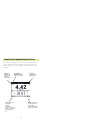
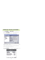
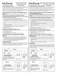
1
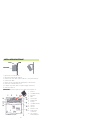
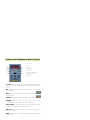
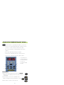
Power Focus
Quick Guide
SAFETY INSTRUCTIONS
When using electric products, basic precautions
should be followed:
❑ THIS EQUIPMENT MUST BE EARTH GROUNDED.
❑ Always disconnect the equipment from the mains,
by pulling the plug, before opening it for installation,
service etc.
❑ Do not use this product near water.
SCOPE
GETTING ST
AR
TED
STAR
ARTED
– Installation check list
– Installation procedure
– PF Compact Interface
– PF Graph Interface
– ToolsTalk PF Interface
3
BASIC PROGRAMMING
– Pset with PF Compact
– Pset with Graph
– Pset with ToolsTalk PF
13
CONFIGURA
TION
CONFIGURATION
– System
– I/O set up
– Communication
– Identifier
19
ADV
ANCED PROGRAMMING
ADVANCED
– Multistage
– Job
– Cell set up
– Synchronization
26
OTHERS
– Monitoring
– Statistics
– Service
– Event code list
32
2
INST
ALLA
TION CHECK LIST
INSTALLA
ALLATION
Power Focus is Atlas Copco’s latest generation of control and
monitoring systems for electrical tools. The fastening system
consists of:
oller
– A Power Focus contr
controller
oller. Three different hardware units are
available. Only the user interface differs between the models.
PF Compact
PF Graph
PF Colour
– A RBU
RBU, Rapid Backup Unit enabling a special level of
functionality (Bronze, Silver, Gold and DS).
– And of course a cable and a tool
tool. The Tensor S tool is
available in different configurations and torque ranges.
3
INST
ALLA
TION PROCEDURE
INSTALLA
ALLATION
Lock
Wall
Controller
1)
2)
3)
4)
5)
6)
7)
8)
Open the lock mechanism.
Open the Controller by pulling it.
Connect the tool cable, power cable etc. (see picture below)
Connect the RBU.
Check the GFI (Ground Fault Interruptor) is switched on.
Close the Controller and lock it.
Connect the power cable to a power supply (115/230 V).
Turn the power on.
IMPOR
TANT! Whenever replacing a tool, always turn the power off.
IMPORT
1.
2.
3.
4.
5.
6.
7.
8.
9.
10.
11.
12.
13.
4
Printer
Serial#2 (RS232)
Ethernet
RBU
Tool output
Digital input
Relays
Serial#1 (RS232)
I/O-bus
I/O-bus
Remote start
Main power
connector
GFI, Ground
Fault Interruptor
POWER FOCUS 3000/3100 COMP
ACT DISPLA
Y
COMPACT
DISPLAY
1
5
2
6
3
4
7
8
1.
2.
3.
4.
5.
6.
7.
8.
n x OK
OK
NOK
JOB OK
ALARM
PROG CONTROL
AUTO SET
STAT
1. n x OK lights up when the number of approved rundowns
corresponds to the number (batch size) programmed into Power
Focus.
2. OK indicates when the result of the rundown is within the
specified limits.
3. NOK lights up when the result of the rundown falls outside the
specified limits.
4. JOB OK light indicates when the result of the Job is complete.
5. A L A R M lights up when alarm message needs to be
acknowledged. Can also flash as service indicator.
og. Contr
ol. A steady green shows that keypad is unlocked.
6. Pr
Prog.
Control.
If locked, Q-mark and Enter can still be used.
7. Auto Set light indicates when the Auto Set programming
function is active.
AT lights up when the calculated values fall outside statistical
8. ST
STA
control limits.
5
POWER FOCUS 3000/3100 COMP
ACT KEYP
AD
COMPACT
KEYPAD
Question Mark – by pushing this button, you can see:
– Power Focus model alternating with software version
(G=Gold, S=Silver, B=Bronze and DS=DS RBU).
– SW version program code alternating with version
number.
– Motor type alternating with type number.
– Current Pset alternating with the current Pset ID.
– Current Pset alternating with the current Job ID.
1
5
3
2
4
1.
2.
3.
4.
5.
6.
Plus Button (+)
Minus Button (-)
Function Button
Auto Set
Question Mark
Enter
6
Selecting Pset
1) Press the Function button four times and F4/Pset
alternates in the display if the Pset Select Source
is Keyboard.
2) Press Enter to access the available Psets.
Browse existing Psets by pressing the +/- keys.
3) Press Enter to select a Pset and exit.
6
/
POWER FOCUS 3000/3100 GRAPH FRONT P
ANEL
PANEL
The Power Focus Graph offers an LCD with
extensive information and a full keypad
allowing full programming.
14
14
1
9
2
10
3
11
4
12
8
5
6
13
7
1.
2.
3.
4.
5.
6.
Soft KEYS
RESULT
CHANButton
PSet
PRINT
Question
mark KEY
7. CANCEL
KEY
8. PROG
9. ARROW
KEYS
10.KEYS with
numbers and
letters
11. CI
12. Enter
13. O K
14. Indicator
lights
The indicator lights of the Power Focus Graph are
similar to the Compact.
Press the Prog key to enter programming mode/
programming tree.
Press the Result key to exit programming.
The CHAN keys are used to select channels in
a programmed Cell.
The Ar
Arrrow keys allow you to move the cursor around
the programming tree.
The Number keys can be used both for numbers and
letters by pressing them several times.
The Print key allows you to print a report. The printer
must be connected to the parallel port on the back of
the controller.
7
POWER FOCUS 3000/3100 GRAPH DISPLA
Y
DISPLAY
The Power Focus display monitors results and programming. It
can be configured to show information from any Power Focus
within a Cell. This is only an example, all selection fields can be
configured.
Channel
number: The
number of the
monitored
channel (tool)
Parameterset /
Multistage number
which is just active
View Pull-up menu
for switching
between:
Last Results
Statistics, Stat Chart
Trace, Job, Sync, All
results and Event
log
Number of
tightenings and
(batch size)
Browse: pushing the
soft key allows the
user to switch
function for the lower
right view in runtime
8
TOOLST
ALK POWER FOCUS
TOOLSTALK
ToolsTalk is a very convenient way for programming and monitoring
Power Focus from a PC. Users can communicate with the Power
Focus via the serial port (RS232) as well as over the Ethernet
Ethernet.
If you are familiar with Microsoft Windows®, you will soon be
comfortable with the ToolsTalk interface. The figure below shows:
–
–
–
–
the
the
the
the
Menu row (1),
Selection panel (2),
Toolbar (3) and
PF Map (4).
1
2
3
4
9
CONNECTING TOOLST
ALK SERIALL
Y
TOOLSTALK
SERIALLY
1) There are two serial ports (RS 232). Make sure that you
connect your PC to the correct one marked with a (2) and
placed on the CC-card.
2) Also make sure that the serial cable is connected to the
correct serial com port on the PC. The Com port settings
can be set in Settings.
3)
2)
3) It is important to use the same baud rate settings in
ToolsTalk and in PF. Default baud rate is set to 9600 bit/s. To
change the baudrate on the ToolsTalk side, use Settings
Settings.
And on the Power Focus side, use Config
Config.
4) You are now ready to connect with a double click on the
connect button, placed on the toolbar.
10
CONNECTING TOOLST
ALK VIA ETHERNET
TOOLSTALK
1) Set an IP address and Subnet mask to the Power Focus
you wish to connect to.
With the PF Compact
Compact, connect serially ToolsTalk to the
controller and go under Config – Communication:
– Set the IP address of the connected Power Focus to a unique
number within the network.
– Set the Subnet mask according to network partitioning.
– Store and Restart the Power Focus.
With the PF Graph
Graph, you can also use ToolsTalk serially or the
Keypad in Prog – Config – Remote Communication.
11
CONNECTING TOOLST
ALK VIA ETHERNET
TOOLSTALK
2) Set IP address and Subnet mask to your own PC under
Start / Settings / Local Area Network connection/ Internet
Protocol (TCP/IP) Properties.
2)
Then in ToolsTalk under Options/Settings/Communications/
Ethernet set-up, you can:
3) Select the type of connected Power Focus (Netmaster,
Cellmaster or Controller).
ess of the PF you
oller IP addr
4) Set the Port number and Contr
Controller
address
wish to connect to.
4)
3)
5) You are now ready to connect to the selected PF with a
double click in the PF Map or on the connect button.
12
PSET PROGRAMMING IN PF COMP
ACT
COMPACT
The PF compact keypad allows an Autoset
Programming. The PF will recognise joint
stiffness and adjust the tool for
maximum performance for that
particular joint:
1) Press the AUTOSET button once and
ASEt/Ft appears on the display.
2) Choose final torque target by pressing +/buttons.
/
3) Press the ENTER button once to activate
the Autoset function.
4) The Graph LED, lights up.
5) Make 5-8 tightenings until the Graph LED
lights goes down.
Optimum performance has been found and the system is
ready for production.
Changing Final T
ar
get value
Tar
arget
1) Press the Function button once and F1/Ft alternates
in the display
2) Press Enter to select the new Final Target value. Change the
value by pressing the +/– keys
/
/
3) Press Enter to save and exit
Setting Batch count
1) Press the Function button five times and F5/batS alternates
in the display, indicating that a Pset is selected. Otherwise
F5/---- is displayed.
2) Press Enter to access the Batch Size value.
Change the Batch Size value by pressing
the +/- keys.
3) Press Enter to save and exit.
13
/
QUICK REFERENCE GUIDE
This Pset example is a help when programming with the PF
Graph or ToolsTalk.
Tor
que Contr
ol / Angle Monitoring
orque
Control
ightening
Tightening
Two Stage T
Torque
P123 Final angle
P122 Final angle min
P124 Final angle max
P114 Final tq max
P113 Final Target
Acceptance window
P112 Final tq min
P120 Start final angle
P115 Cycle complete
P110 Cycle start
Angle
Time
P142 Soft start time
P141 End time
P132 Step 2 speed
P130 Soft
start speed
P136 Step 2 ramp
P135 Step 1 ramp
P131 Step 1 speed
Tool speed
P1xx Programming
Open new Pset
P13x Speed/Ramp
P130 Soft start speed
P131 Step 1 speed
P132 Step 2 speed
P135 Step 1 ramp
P136 Step 2 ramp
P10x Contr
ol Strategy
Control
P100 Tq con/Ang mon
P101 Two stage
P14x T
ime
Time
P141 End time
P142 Soft start time
P144 Cycle abort timer
P11x T
or
que
Tor
orque
P110 Cycle start
P111 First target
P112 Final tq min
P113 Final target
P114 Final tq max
P115 Cycle complete
14
P15x Batch
P150 Batch count
P151 Batch size
P12x Angle
P120 Start final angle
P121 Measure angle to
- Peak tq
- Angle peak
- Cycle complete
P122 Final angle min
P124 Final angle max
PSET PROGRAMMING IN PF GRAPH
Navigate through the menus with the
arrow buttons on the front panel and
confirm selections with the Enter
button.
1) Press the PROG button and the
programming window will appear.
Then, Select Pset – Programming – Control.
2) Select Control Strategy
You can choose between:
– Torque Control
– Torque Control / Angle
Monitoring is defaut prog.
– Torque Control / Angle Control
(Tq con / Ang con [AND]/[OR])
– Angle Control /
Torque Monitoring
– Reverse Angle
– Rotate spindle forward/reverse
– Click wrench
ightening strategies
3) Select T
Tightening
You can choose between:
– One stage
– Two stage
– Quick Step
– Ergoramp
Two Stage is default prog. The tool operates at high speed during
the first stage and at lower speed during the second stage. The
tool stops for about 50 ms between stages to reduce joint
relaxation.
15
PSET PROGRAMMING IN PF GRAPH
4) Go back one level and select
To rrque.
que.
Set the Torque parameters
and Store.
Go back one level and select
Angle.
Set the Angle parameters and
Store.
5) Continue the programming by
setting in the same manner:
Speed and Ramp
Step 1 Speed is the speed
used during the rundown.
When First Target is reached,
the tool slows down to Step 2
Speed to tighten the second
stage. To finish the tightening
the tool goes into Zoom Step
Speed for operator comfort
and minimization of overshoot.
Time
Soft Start time facilitates
screw engagement by turning
at a very low speed during the
soft start time.
Batch count
Enables you to control the
number of tightenings. You can
also lock the tool at Batch OK.
6) Press Store to save the Pset.
16
PSET PROGRAMMING IN TOOLST
ALK
TOOLSTALK
1) Right click on Pset in PF
Map and select create
new Pset.
2) The Create New Pset
window pops up.
Name (optional) the Pset
and click OK.
3) The programming window appears. Select the
following and click store.
– Control Strategy
– Tightening Strategy
– Rundown angle
– Zoom step
– PF 2000 compatible
Please refer to the Graph
programming for explanation of the different parameters.
17
PSET PROGRAMMING IN TOOLST
ALK
TOOLSTALK
que or Angle in the
4) Click on Tor
orque
menu tree and set the Torque
and Angle parameters.
Hint! Display limits for each
parameter by holding the
cursor in respective parameter
box.
5) Continue the programming by
setting Speed and Ramp
Ramp, Time
and Batch Count parameters
in the same manner.
6) Click Store to save the Pset.
QUICK PROGRAMMING
You only need to set the following
parameters:
– Control Strategy
– Joint Angle
– Final Target
All other parameters are calculated and set automatically by
Power Focus.
18
CONFIGURA
TION
CONFIGURATION
The configuration set-up contains the configuration parameters
which are unique for each Power Focus unit. It contains four
subgroups:
1
2
3
4
1. The System set-up contains basic Power Focus features such
as name, language and the appearance of the Power Focus
Graph display.
2. I/O Setup – Apart from the internal I/O ports it is also possible
to connect up to 15 external I/O devices to the Power Focus
I/O bus.
3. Communication – Ethernet and Serial communication links,
ToolsTalk and database applications such as ToolsNet, etc. IP
addresses and baud rates etc are set-up in this window.
o t o c o l s – This window contains the settings for each
4. P rro
communication protocol.
19
SOCKET SELECTOR SETUP
The selector is an accessory that can guide the operator through
a JOB sequence with LEDs. When a socket is lifted, the
corresponding Pset will be selected. The selector is available in 4
and 8 positions.
Selector
4 positions
1) Hardware Setup: Connect the selector via I/O bus to the
Power Focus. Make sure that the I/O bus is terminated.
e Setup: Go in ToolsTalk under Configuration and I/O
2) Softwar
Software
Setup and select Selector Pset under appropriate I/O. The device
number on the hexagonal switch in the back of the socket tray
should have the same number as the device number where the
tray is set up in ToolsTalk.
3) Click on Set and drag the Psets that you have created before
in the desired positions of the socket tray.
4) Store. Then go back to Other I/Os and set the Pset select
Source to Selector.
20
RE-ALARM & I/O EXP
ANDER SETUP
EXPANDER
The RE-alarm gives status information to users using lights and/or
audible signals. It is connected to the Power Focus on the I/O-bus.
REA larm
RE-A
Detailed setup
setup: please refer to the Selector as it is very similar.
It is possible to configure the information you want to see.
Config.
of the 4
alarms
The I/O Expander enables the connection of several inputs and
relays when more than those built-in are required. There are 8
inputs and 8 relays with the same functionality as the four built-in
I/Os. Each input and relay can be configured individually.
I/O Expander
Detailed setup
setup: please refer to the Selector as it is very similar.
21
OTHER I/O SETUP
Other inputs and outputs to the Power Focus are set-up in this
branch, most notably are the Tool start select source, Job
select source and Pset select source.
Tool star
startt select source can be:
– Tool trigger
– Digital Inputs
– Fieldbus
– Sync Start
Job select source can be:
– Off
– Digital Inputs
– Ethernet Serial
– Identifier
– Fieldbus
– PF Keyboard
Pset select source
source:
– Off
– Selector
– Digital Inputs
– Ethernet Serial
– Identifier
– Fieldbus
– PF Keyboard
The ”Other I/O Setup” can often be the problem source for
tr
ouble shooting if the Power Focus behaves incor
trouble
incorrr ectly
ectly..
22
COMMUNICA
TION / PROTOCOL
COMMUNICATION
Power Focus
communicates by both
Ethernet and Serial
communication links
and can tie in with
ToolsTalk and database
applications such as
ToolsNet, etc. I P
addresses and baud
rates etc are set-up in
this window.
Remote com
The IP address configuration of the Power Focus is set-up in this
branch. This is a prerequisite if you want to communicate with
the Power Focus via Ethernet or set up a cell (see cell programming).
ToolsNet set-up
The ToolsNet communication is turned on
and configured in this
branch. Make sure that
the Power Focus is
set-up in accordance
with IP address and
port number of the
ToolsNet ser
ver
server
ver..
Multicast set-up
Multicasting of tightening results is turned-on and configured in
this branch. The multicasting must be turned on in order for the
Factory Overview Software to work.
23
IDENTIFIER SETUP
With Power Focus it is possible to use a barcode (typically the VIN
Number) to select Jobs or Psets.
1) Start by connecting ToolsTalk and the Identifier (Barcode reader)
to the Power Focus.
2) In ToolsTalk click on Identifier in the PF Map.
Set Identifier input source and click on Set Significant No.
2)
24
IDENTIFIER SETUP
3) Select the positions where the significant information is located
in the barcode. 1 – 10 numbers can be selected (it is not
necessary to set them in a row).
3)
4) Click on Set Identifier Setup.
Enter a string in the Add Identifier string field and click Add.
5) Once all strings are entered, associate them with a Pset,
Multistage or Job by double clicking in the corresponding cell
in the matrix.
4)
5)
25
MUL
TIST
AGE PROGRAMMING IN TOOLST
ALK
MULTIST
TISTAGE
TOOLSTALK
The Multistage feature allows you to dynamically link up to eight
(8) parameters in several steps to perform a sequence of operations. It is used for joints with high relaxation.
1) Create the different
Psets separately.
2) Right click on Multistage in the PF Map
and select Create
New
Multistage ,
choose ID, Name and
click OK.
3) Click Add to open a
window where you
can select Psets to
be included in the
Multistage.
4) Edit the Multistage
Properties and Store
your programming.
26
JOB PROGRAMMING
This is a typical application for
a Job: an object with bolts that
require different torque values
and number of tightenings:
1. Four bolts that require
torque X.
2. Three bolts that require
torque Y.
3. One bolt that requires torque
Z.
You do the programming like this:
1) Right click on Job in the PF Map and select Create New.
2) The Job window appears where you will find a list of all the
available Psets and Multistages.
3) Select the desired Psets and Multistages and add them to the
Edit Job list by clicking either Manual select or Auto select.
4) Set the batch size.
5) Select and set Job options parameters.
Note! Forced job must be selected if Auto Select is used.
27
CELL SETUP PROGRAMMING
The Cell and Net concept is part of the Silver and the Gold software
versions. A Cell consists of one Cell Master and a maximum of 19
Cell Members. Here is an example with 3 Cell members.
Cell Members
Cell Master
Cell Member
Sw it c h
1) Connect the different Cell members with an Ethernet cable via
a switch.
2) Configure Password and Name for Cell master:
– Set Channel ID to a unique number within the cell [1-20].
– Set Cell ID to a unique number within the network.
Click Store to save the settings.
28
CELL SETUP PROGRAMMING
3) Complete Config-Communication for the Cell master:
ess
– IP addr
address
ess, Subnet mask and Default router.
– Define a Cell Master by setting Cellmaster IP address equal
to the IP address of the same controller.
– Click Store to save the settings.
– Restart the Power Focus!
4) Repeat a similar programming for cell members but change
the channel ID and set Cell Master IP address in the
appropriate field.
Now you are ready among others to program a Cell Job where
several Power Focus units are involved. Cell Jobs run in the same
efer
ence as the main controller.
way as ordinary jobs with a Job rrefer
eference
29
SYNCHRONISA
TION PROGRAMMING
SYNCHRONISATION
With the Gold RBU version, you have the possibility to create a
Sync Group and synchronise 2 to 10 spindles to perform the same
task simultaneously. This is an example with 4 synchronized Power
Focus units.
Hardware setup
1) Connect all Sync Members and the Sync Reference via the I/Obus. Do not forget to terminate the I/O bus with terminators.
4
3
2
Sync Master
Back pannel
+
+
+ I/O Bus T
Ter
erminators
er
minators
2) Configure the 4-pin remote start connector
on remote start for the sync members and
according to the selected start signal input on
the Sync Reference.
30
SYNCHRONISA
TION PROGRAMMING
SYNCHRONISATION
Software Setup
1) Make sure that all Power Focus units in the synchronised
group are part of the same Cell (see cell programming).
2) Decide which units should act as Sync Reference and Sync
Members according to HW setup.
3) For the Sync members
members:
– Set Sync reference IP address in the appropriate field.
– Set Tool start select source to Sync start.
– Configure the 4-pin connector on the back panel for
remote start.
– Re-start the Sync Member.
– Repeat step 1-4 for all Sync Members.
4) For the Sync reference
reference:
–
–
–
–
Set Sync reference IP address equal to own IP address.
Create the Sync Group List and set other Sync options.
Re-start Sync Reference.
Pset programming, and I/O-setup is done only on the Sync
Reference.
31
MONITORING IN TOOLST
ALK
TOOLSTALK
ToolsTalk provides a number of monitors designed to present
extensive information about various functions of Power Focus.
Among others are:
Operator Monitor
Detailed information
about the tightening
operation is presented.
Get all results
Power Focus can store up to 5000 individual tightening results.
With the Get All Results option, the user is able to retrieve and
view these.
By choosing Save To File the results are saved into a text-file. The
user can also choose to open and view the results in Microsoft
Excel® by selecting Open In Excel.
32
TRACES / ST
ATISTICS
STA
These are three different ways to activate the traces
traces:
1) Select Window in Main Row and then click on Activate->Trace.
2) Use the PF map. Double-click on Trace.
3) Use Trace icon in Toolbar. Click on the icon.
Statistics
The statistic setup can be found under Pset – Statistic
Programming. There you are able among others to program
statistical alarms like SPC, etc.
33
SERVICE SETUP
Under Diagnostic – Configuration – Tool service, this window shows
the service status of the tool.
Here you can see information about last service date and the
number of tightenings after service. By turning the Service
indicator alarm On, the Power Focus will automatically alert the
user when the service interval has expired.
34
EVENT CODES
Event code
Group
Description
E000-E099
0
Rundown failures
E100-E199
1
Event-related errors
E200-E299
2
User input error
E300-E399
3
Statistical errors
E400-E499
4
Communication errors
E500-E599
5
Hardware errors TOOL
E600-E699
6
Hardware errors DC3000/MC3000
E700-E799
7
Hardware errors
E800-E899
8
Software errors
E900-E999
9
Errors MMI3000
Event
Code
Event Text
Acknowledge
Explanation
E000-E099: Rundown errors
E001
Torque LO
-
Start button was probably released
to early. Let the tool «finish» the
tightening.
E002
Torque HI
-
The programming is probably bad.
Make sure that you have some
movement on the socket in the
second stage.
E003
Torque measurement
possibly invalid
-
E004
Angle1 LO
-
E005
Angle1 HI
-
Check the programming or the joint
E006
Angle2 LO
-
Check the programming or the joint
E007
Angle2 HI
-
Check the programming or the joint
Check the programming or the joint
E100-E199: Event-related errors
E101
Pset invalid (check sum error)
E102
Rundown prohibited due to
Lock on Reject
Yes
-
This error code is displayed after a
NOK tightening when the function
Lock on Reject is activated. In this
case the tool is disabled, the tool
can be unlocked with a digital input
or with the tool ring.
E103
Forward direction prohibited
via digital input
-
The forward direction is prohibited
via the digital input.
35
E104
Reverse direction
prohibited
-
The reverse direction is prohibited via digital
input or in Job mode. The reverse direction
is prohibited in job mode when Lock at Job
Done is selected or batch mode is configured
to NOK+OK.
E105
Reverse direction
prohibited via
ToolsTalk
-
The reverse direction is prohibited via Tools
Talk.
E106
Rundown prohibited
due to active
CycleHold
-
The tool is locked due to Cycle hold.
E107
Rundown prohibited
due to Line Control,
batch not enabled
-
A job using Line Control is selected. The job
does not start until Line Control Start signal
is received.
E108
Rundown prohibited
due to keypad usage
-
E109
Pset revision not
supported by this SW
-
E110
Configuration
revision not
supported by this SW
-
E111
MC Rundown timeout
-
E112
Rehit
E113
Current limit reached
– Rundown aborted
Yes
E114
OpenEnd Reference
position not found
Yes
E115
Direction uncertain
-
E116
SelfTap max torque
reached – Rundown
aborted
-
E120
MC Motortuning
failure
Yes
Motor tuning failed. The trigger could have
been released before the end of the motor
tuning or the tool has a defect.
E121
OpenEnd tuning
failure
Yes
This error indicates that the open end
tuning command has not been successfully
performed. Either the command was aborted
by the operator or the command could not be
performed for any other reason.
E126
Multistage aborted
-
This error indicates that the current running
multistage has not been performed entirely
(the drive has been shut off or the tool trigger
was released before the end).
The rundown was not terminated before the
drive time out (2 minutes).
The current limit has been reached; the drive
is disabled.
36
E127
PVT shut off
-
This error indicates that the drive was shut off in the
Self-tap or prevail phase of the rundown.
E128
Trigger lost
-
When the function Trigger lost is activated in the
Pset, this error indicates that the trigger of the tool
was released before final target.
E129
Torque lower
than target
-
When the function torque lower than target is
activated in the Pset, this error indicates that the
torque result is below final target. The torque status
is NOK even if the torque result was larger than final
torque min.
E130
Post view torque
shut off
E131
Tool
Disconnected
This error indicates that the tool is not connected
Yes to the controller or that the tool cable has been
damaged.
E132
Wrong tool start
input setting
1) Check if the remote start wiring in the PF is
correctly set in accordance to the settings in the
Yes Configuration parameters (C220).
2) Check if the tool trigger is constantly pressed or if
there is some malfunction in the tool.
E133
Forward direction
prohibited via
ToolsTalk
-
The forward direction is prohibited via Tools Talk.
E134
MC Target input
active at start
attempt
-
The target signal is active in the drive though the
tightening has been acknowledged by the CC-card.
E135
MC No start Ack
from CC
-
No start acknowledgement has been received by the
MC drive from the CC-card (timeout 32s)
E136
Rundown
prohibited due to
batch locked
-
This error is displayed if the function lock at batch
OK is enabled and when the batch is completed. The
tool can only be unlocked via a digital input.
E137
Rundown
prohibited via
field bus
-
The rundown is prohibited via field bus.
E138
Wrong tool start
input source
-
It is only possible to start the tool from the selected
tool start select source.
E139
Rundown
prohibited via
Open protocol
-
The rundown is prohibited via Open protocol.
E140
Insert user ID
card to release
tool
-
The tool is locked, the user must insert his ID card in
the card reader to release the tool.
E141
MC Current
Monitoring
torque deviation
Post view torque conditions were not fulfilled.
Yes
37
E142
MC SyncroTorque
diffstop
-
E150
Job client does
not respond
-
When running a Cell Job, this error is displayed by
the job master when one of the job members does
not respond.
E151
Job in OFF mode
-
It is not possible to select a new job, the PF3000 is
in Job Off mode.
E152
PF locked in job
mode
-
This error appears when in a forced cell job an
attempt is made to tighten with a controller which
is not currently active or when a controller has
performed all tightenings.
E153
Not Ok to select
new job
-
A job is currently running, it is not possible to
select a new job until the first is finished in some
way (completed or aborted). This message is also
displayed if a job is selected on a job member.
E154
Remote job
running
-
When running a Cell Job, this is displayed by the
job members when a cell job is selected on the
job master.
E155
Remote job
aborted
-
When running a Cell Job, This is displayed by the
job members when a cell job is aborted.
E156
Job members lost
-
When running a Cell Job, this is displayed by the
master when it has lost contact with one of its job
member.
E157
Job reference lost
-
When running a Cell Job, this is displayed by the
job members when they have lost contact with
their Job Master.
E158
Invalid Job ID
-
When the selected job does not exist.
E159
No Pset In
Selected Job
-
When the selected job does not contain any Pset.
E160
Job select source
not valid
-
Attempt to select a Job with the wrong input
source.
E161
Line Control
Alert 1
-
The line control has been activated, and the first
control alert limit has been reached.
E162
Line Control
Alert 2
-
The line control has been activated, and the
second control alert limit has been reached.
E180
Euchner Ident
System only
supports Siemens
3964R protocol
-
The protocol settings for the serial COM port 1
is not set to 3964R, it is not possible to use the
Euchner Ident System with this configuration.
E181
Not possible to
read ID card
-
It was not possible to read the ID card inserted in
the Euchner system.
38
E200-E299: User input error
E201
First target > Final
target
-
E202
Final target > Tool
max torque
-
E203
First target < XX % of
tool max torque
-
E204
Final target < YY % of
tool max torque
-
E205
Pset not open
-
E206
Pset number invalid
-
An attempt was made to do a tightening with
the wrong Pset within a job.
E207
Wrong Pset Select
Source
-
Attempt to select Pset from a source not
specified in the Cset.
E208
Not Ok to select new
Pset
-
It is not allowed to select new Pset when the
already selected Pset is auto selected by Job.
E233
Final target range
error
-
This error code is displayed when an attempt is
made to tighten with a final target out of range
(larger than tool max torque or 9999).
E234
Start final angle
range error
-
This error code is displayed when an attempt
is made to tighten with a start final angle out
of range.
E235
Target angle range
error
-
E236
Configuration set
inconsistent
E237
Strategy
Configuration error
-
No valid control strategy was chosen for the
stored Pset.
E238
Not possible to run a
multistage with a click
wrench Pset
-
An attempt was made to perform a multistage
tightening containing at least one Pset with a
click wrench strategy.
E240
Password Incorrect
Input Source
-
The password is entered from an invalid source
according to the configuration.
E241
Password Access
Denied
-
E242
Password Locked
Out
-
Yes
This error code is displayed if one device on the
IO bus has the right ID but the wrong type (for
example a selector is connected and a re-alarm
is configured).
39
E250
Maxtime
for first
tightening run
out (job)
-
This message is displayed and the job is terminated
if the first tightening is not performed within the
specified time.
E251
Maxtime to
complete job
run out
-
This message is displayed and the job is terminated if
the job is not completed within the specified time.
E300-E399: Statistical errors
E333
Not allowed
subscription
-
The requested statistic subscription is not allowed.
For example it is not allowed to set an angle statistic
subscription for a Pset using only the torque control
strategy.
E334
No statistic
available for
this Pset
-
The Pset strategy is not suitable to calculate statistics
(no strategy is chosen, DS control)
E335
Not enough
data
-
No enough data were available to calculate the
statistic control limits.
E336
Mem alloc fail
-
It was not possible to allocate enough memory for
the statistic subscription.
E340
Xucl tq
-
The last subgroup mean torque value is larger than
the upper control limit.
E341
Xlcl tq
-
The last subgroup mean torque value is lower than
the lower control limit.
E342
Rucl tq
-
The last subgroup range torque value is larger than
the upper control limit.
E343
Rlcl tq
-
The last subgroup range torque value is lower than
the lower control limit.
E344
Cp tq
-
The torque Cp is lower than 2.
E345
Cpk tq
-
The torque Cpk is lower than 1,33.
E354
2sigma x tq
-
Trend deviation alarm, the last subgroup torque
average is outside Xtq-bar-bar – 2 sigma.
E355
2sigma r tq
-
Trend deviation alarm, the last subgroup torque
range average is outside Rtq-bar-bar – 2 sigma.
E360
Xucl ang
-
The last subgroup mean angle value is larger than
the upper control limit.
E361
Xlcl ang
-
The last subgroup mean angle value is lower than the
lower control limit.
40
E362
Rucl ang
-
The last subgroup range angle value is larger than
the upper control limit.
E363
Rlcl ang
-
The last subgroup range angle value is lower than the
lower control limit.
E364
Cp ang
-
The angle Cp is lower than 2.
E365
Cpk ang
-
The angle Cpk is lower than 1,33.
E366
7inc x ang
-
Trend deviation alarm, the subgroup angle mean
value has increased 7 times consecutively.
E367
7dec x ang
-
Trend deviation alarm, the subgroup angle mean
value has decreased 7 times consecutively.
E368
7inc r ang
-
Trend deviation alarm, the subgroup angle range
value has increased 7 times consecutively.
E369
7dec r ang
-
Trend deviation alarm, the subgroup angle mean
value has decreased 7 times consecutively.
E370
7above x ang
-
Trend deviation alarm, the subgroup angle mean
value has been above the average mean value
of the average of the last ten subgroups 7 times
consecutively.
E371
7below x ang
-
Trend deviation alarm, the subgroup angle mean
value has been below the average mean value
of the average of the last ten subgroups 7 times
consecutively.
E372
7above r ang
-
Trend deviation alarm, the subgroup angle range
value has been above the average range value
of the average of the last ten subgroups 7 times
consecutively.
E373
7below r ang
-
Trend deviation alarm, the subgroup angle range
value has been below the average range value
of the average of the last ten subgroups 7 times
consecutively.
E374
2sigma x ang
-
Trend deviation alarm, the last subgroup angle
average is outside Xang-bar-bar – 2 sigma.
E375
2sigma r ang
-
Trend deviation alarm, the last subgroup angle range
average is outside Rang-bar-bar – 2 sigma.
41
E400-E499: Communication errors
E401
Duplicate device IDs on
IO bus
Yes
E402
IO bus restarted
Yes
The IO bus has been restarted.
E403
IO device not
responding
Yes
The I/O device is not properly connected or
the ID of the device is not the same as the
one configured.
E404
Selector is not
connected or not
responding
Yes
The selector is not properly connected or the
ID of the selector is not the same as the one
configured.
E405
IO Expander is not
connected or not
responding
Yes
The I/O expander is not properly connected
or the ID of the I/O expander is not the same
as the one configured.
E406
RE-alarm is not
connected or not
responding
Yes
The Remote alarm is not properly connected
or the ID of the Remote alarm is not the same
as the one configured.
E408
Multiple devices of
same type on IO bus
-
E409
Multiple selectors on
IO bus
-
E410
No selector found and
Pset source is IO bus
-
E411
Rotary selector has
ID <> 1
-
E412
IO expander has ID
<> 2
-
E413
RE Alarm has ID <> 3
-
E414
Remote display has
ID <> 4
-
E415
4socket selector has
ID <> 5
-
E416
8socket selector has
ID <> 6
-
E433
No RBU present
E434
RBU Timeout
Yes
RBU did not respond to command from PF.
E438
RBU file mismatch
Yes
A file with incorrect name or size was
returned to a read request.
E439
RBU signal mismatch
Yes
An unexpected signal received by the RBU
Manager in Idle status.
E440
RBU no files
Yes
Yes
Two IO devices with the same ID are present
on the I/O bus.
No RBU detected at start-up or RBU found
missing at runtime.
42
E441
RBU no answer
Yes
E442
RBU no such file
Yes
E443
RBU full
Yes
E444
RBU packet rejected
Yes
E445
RBU corrupt
Yes
E446
RBU read error
Yes
E447
RBU write error
Yes
E448
RBU delete error
Yes
E449
RBU flush error
Yes
E450
RBU list error
Yes
E451
RBU Update Failed
Yes
E460
FieldBus Type Mailbox
Message Fault
-
E461
FieldBus Type Gen Com
Fault
-
E462
FieldBus Mailbox
Message Fault
-
E463
FieldBus Gen Com
Fault
-
E464
FieldBus Hardware
Fault
Yes
The FieldBus module is broken and has to be
replaced.
E465
FieldBus Dip switch
Error
-
The software tries to configure the value of
node address or baudrate, But the address
switch on the FieldBus module is not in the
right position to enable software setting. Set
switches in the right position, then turn on
the power.
E466
FieldBus Offline
-
E467
FieldBus Configuration
Fault
-
E468
FieldBus Hardware
Mismatch
-
E469
FieldBus Init Error
-
E470
FieldBus PCP error
-
RBU responds with an answer not matching
the last request. This is probably due to
duplicates sent when the PF does not
acknowledge packages.
RBU Erase failed.
One of the database processes failed to
synchronise the NVRAM with the RBU.
The FieldBus went from Online to Offline.
This is just a warning.
The FieldBus module installed in PF 3000 is
not the same FieldBus type as configured
with TTPF. Change FieldBus module or
configuration to get a match.
43
E480
Channel ID not valid
Yes
The channel ID configured is not within
the limits permitted. The channel ID must
configured between 1 and 20.
E481
Cell member
registration failed
Yes
The cell member registration failed because
one cell member is already registered with the
same channel ID.
E490
Cell ID not valid
Yes
The cell ID configured is not within the
limits permitted. The cell ID must configured
between 1 and 999.
E491
Net member
registration failed
E492
Software version
not compatible with
net-cell
-
Yes
The net member registration failed because
one net member is already registered with the
same cell ID.
It is not possible to build a net with two
different revisions of the software.
E500-E599: Hardware errors TOOL
E501
Tool overheated
-
E502
Tool service interval
expired
-
The tool is too hot. The drive is disabled.
E511
Tool-PF3000 size
mismatch
Yes
Mismatch between the tool and the controller
(for example S4/S7 tool connected to a S9
controller).
E512
Tool revision not
supported by this
drive SW
Yes
The tool is not supported by the drive (drive
version too old).
E513
Tool EEPROM
corrupt – service tool
Yes
E514
Tool EEPROM
corrupt – Motortune
Yes
E515
Tool commutation
sensor error
Yes
Commutation sensor failure.
E516
Rotor magnet
remains out of range
Yes
Rotor magnet remains out of range.
E517
Tool maxtorque or
Gear Ratio out of
range
Yes
E518
Tool normalisation
out of range
-
E534
Illegal data error
(Current monitoring)
Yes
44
E535
Torque transducer
error
Yes
Cables to transducer cut off or shorted.
E536
No transducer (sensor)
Yes
Cables to transducer cut off or shorted.
E537
Calibration not OK,
offset outside limits
Yes
Calibration limits out of bounds.
E538
Calibration not OK,
CalVal outside limits
Yes
Calibration value outside limits.
E539
Calibration not OK,
Offset changed > 5%
of max value since last
calibration
-
Calibration not OK, Offset changed > 5% of
max value since last calibration.
E540
Calibration not OK,
CalVal changed > 5%
of max value since last
calibration
-
Calibration not OK, calibration value
changed > 5% of max value since last
calibration.
E541
Other calibration error
Yes
E600-E699: Hardware errors DC3000/MC3000
E601
Dcbus LO at start of
rundown
Yes
DC voltage too low
E602
Dcbus HI during
rundown
Yes
DC voltage too high
E603
DC3000 overheated
E604
24V output error
E605
Dcbus HI at start of
rundown
-
E611
DC3000 EEPROM
corrupt (csum error)
Yes
E612
MC3000 EEPROM
corrupt (csum error)
Yes
E613
Config1 EEPROM
corrupt (csum error)
Yes
E614
FirmWare corrupt (csum
error etc)
Yes
E615
Option definition HW/
SW mismatch
Yes
E616
Current measurement
offset error
Yes
Yes
The drive is too hot, drive disabled
24 V output disabled (overload or short
circuit)
Firmware corrupt (check sum error)
45
E617
Current measurement
gain error
Yes
E633
SW mismatch CC <->
MC: Too old MC SW
Yes
E634
SW mismatch CC <->
MC: Too old CC SW
Yes
E700-E799: Hardware errors
E700
PF started
-
This error code is only visible in the error log
and used when the PF3000 is started.
E800-E899: Software errors
E801
Database incompatible
with PF software
Yes
E802
NVRAM range check
error
Yes
E803
NVRAM size check error
Yes
E804
Database is corrupt
Yes
Yes
This error is displayed after start-up
when the RBU is missing, or when the
RBU revision cannot be supported by the
controller (e.g bronze RBU on a graph unit),
or when the RBU license file is missing or
cannot be read by the boot code.
E805
(PF Model unknown)
E806
Failed to read from
NVRAM
-
E807
Failed to write to
NVRAM
-
E811
DPRAM range check
error
Yes
E821
No calibration ACC from
control
Yes
Tightening initialisation phase failed.
Hardware failure.
E822
No Job ACC from
control
Yes
Tightening initialisation phase failed.
Hardware failure.
E823
No calibration result
Yes
No calibration was received from the drive
during the tightening initialisation phase
(timeout 100 ms).
E824
Cycle abort timeout
-
E831
Autoset wrong angle
-
No tightening result was received from the
drive before the Cycle abort timeout. The
Cycle Abort timer is configurable in the Pset.
Auto set could not be executed, the angle
results of the tightening performed were
null.
46
E832
Autoset small angle
-
Auto set could not be executed, the angle
results of the tightening performed were
too small (lower than 15 degrees).
E833
Autoset tight NOK
result
-
The Auto set could not be executed, four
NOK tightenings were performed.
E834
Autoset rejected Pset
in CCW direction
-
The Auto set was not allowed by the
PF3000 for this Pset because the Pset was
configured in the CCW direction. Auto set is
only permitted on CW Pset.
E840
Feature Not Available
In Software Revision
E851
Connection with Tools
Net server lost
E855
Connection fatal error
E856
Router unreachable
The router programmed in the
configuration setting could not be reached.
Check the network configuration and in
particularly the sub net mask and the
default router.
E857
Reboot needed before
changes take effect
The configuration changes will not take
effect before a system reboot.
E858
IP address already
in use
Yes
E859
IP address collision
-
Another system attempts to use the same IP
address as this PF3000.
E860
Memory Allocation
Error
-
It was not possible to allocate enough
memory to allow the Tools Net process to set
a result subscription.
E862
Ethernet overload Error
E863
IP Port already in use
This error is displayed if when attempt
is made to run multistage with a bronze
version, or handle a Pset with a Pset ID
larger than the max number of Pset (larger
than 64 in a bronze version or larger than
250 in a silver or gold version).
-
The connection with the Tools Net server
was lost, the PF3000 is trying to reconnect.
The Tools Net server might be down or it
might be an Ethernet cable problem.
The IP address of this PF3000 is already in
use by another system.
The Ethernet driver of the PF3000 is
switched off due to an overloaded network.
Yes
An attempt was made to bind a TCP or UDP
socket to a port already in use. For instance,
a customer protocol might be using the
same port as ToolsTalk.
47
2005:1
9833 1431 01
This quick guide is based on PF 3000 E3 Manual
www
.atlascopco.com
www.atlascopco.com