1
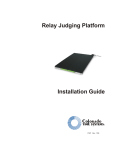
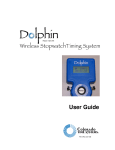
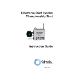
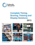
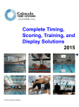
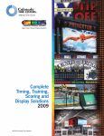
Water Polo Shot Clocks
(SCs)
User Guide
F732 Rev. 0804
Colorado Time Systems
Corporate Office
1551 East 11th Street
Loveland, CO 80537 USA
Sales : 800-279-0111 or +1 970-667-1000
Service: 800-287-0653 x256 or +1 970-667-1000 x256
Service Fax: 970-667-1032
Web: www.coloradotime.com
Email: [email protected]
Part Number F732, Rev. 0804
©2004 Colorado Time Systems. All rights reserved.
Table of Contents
1 Introduction
Receiving your Equipment . . . . . . . . . . . . . . . . . . . . . .1-1
2 Setup & Operation
Installation . . . . . . . . . . . . . . . . . . . . . . . . . . . . . . . . . . .2-1
Installing the Portable Stands . . . . . . . . . . . . .2-2
Installing the Speakers . . . . . . . . . . . . . . . . . . .2-2
Attaching the Data Cable . . . . . . . . . . . . . . . . .2-3
Operating your Shot Clocks . . . . . . . . . . . . . . . . . . . . .2-4
3 Maintenance
Battery Maintenance . . . . . . . . . . . . . . . . . . . . . . . . . . .3-1
Internal Battery ON/OFF . . . . . . . . . . . . . . . .3-1
Battery Recharging . . . . . . . . . . . . . . . . . . . . . .3-1
Digit Maintenance . . . . . . . . . . . . . . . . . . . . . . . . . . . . .3-2
i
ii
1
Introduction
Dear Customer:
Thank you for purchasing Colorado Time Systems’ water polo shot clocks.
The shot clocks are compact and a very rugged accessory for your water
polo program, designed to deliver years of trouble-free service.
Please follow the instructions in this booklet to ensure proper installation
of your shot clocks and follow the operating instructions to ensure reliable
performance for years to come. If you should experience any difficulty
installing or using your shot clocks, please call Colorado Time Systems’
Customer Service Department at 970-667-1000 ext. 256.
Receiving Your Equipment
When you receive your Colorado Time Systems’ equipment, follow these
steps:
1) Open all shipping boxes.
2) Check all concealed damage immediately upon receipt of equipment.
Report any damage directly to the freight carrier.
3) Use the list below to take an inventory of all items you received. If you
believe one or more parts to be missing, contact our Customer Service
Department immediately.
•
•
•
•
Shot clocks (2)
Speakers (2)
Portable stands (2 sets)
Data cable set with Y-connector
Note: We recommend that you save all shipping boxes and packing material. You are responsible for damage to your equipment if an item is returned
improperly packed.
1-1
1-2
2
Setup & Operation
Installation
Caution: Before beginning the installation process, ensure that your shot
clocks are not plugged in to an electrical source. Turn off your shot clocks,
setting the ON/OFF switch on the printed circuit board to the OFF position.
See Figure A for the location of the ON/OFF switch.
Before beginning, notice that the weather shield on each shot clock is
attached at the right end with a small hook-and-loop patch. Pull the
weather shield out slightly before attempting to slide it to the left to
expose the printed circuit board.
Figure A - Shot clock circuit board components
2-1
Installing the
Portable Stands
Insert the portable stands into the slots at the bottom of each shot clock as
shown in Figure B.
Figure B - Installing portable stands and speaker
Installing the
Speakers
To install the speaker, slide the speaker mounting bracket into the slots in
the top channel of the shot clock as shown in Figure B above. Next, slide
the weather shield to the left to access the printed circuit board. Route the
speaker cable through the opening in the back of the shot clock. Plug the
speaker cable connector into the connector labeled Speaker on the printed circuit board. Repeat the process for the other shot clock.
Note: Do not slide the weather shield back over the shot clocks until you
have finished all cabling steps.
2-2
Attaching the
Data Cable
Locate the data cable set included with your shot clocks. Route the shorter
of the two cables through the opening in the back of the shot clock. Plug
the connector on the cable into one of the Data Cable Jacks on the
printed circuit board. See Figure A for the location of these jacks.
Route this cable to the Y-connector included in this kit. Insert the connector from the shot clock cable into one of the Y-connector jacks. Insert your
scoreboard cable into the other jack on the Y-connector. Insert the other
end of the Y-connector to the Scoreboard connector on the rear panel of
your sports timer as shown in Figure C.
Note: Make sure your sports timer is OFF before attaching the shot
clock/scoreboard data cable.
Figure C - Shot clock cabling diagram
To attach the other shot clock, locate the longer data cable included with
your shot clocks. Route it through the opening in the back of your first
shot clock. Plug its connector into the open Data Cable Jack on your
first shot clock. Next, route the cable to the second shot clock. Slide the
weather shield on the second shot clock back to expose the printed circuit
board. Route the data cable from the first shot clock through the opening
in the back of the second shot clock. Plug the cable connector into one of
the open Data Cable Jacks on the printed circuit board. Refer to Figure
C for a cabling diagram.
Slide the weather shield(s) back into place and press on the right edge to
engage the hook-and-loop fastener to hold the weather shield in place.
This completes the cabling connections.
2-3
Operating your Shot Clocks
Your sports timer program controls the shot clocks. No special operator
intervention is needed. Refer to your Water Polo Software User Guide
for complete instructions.
2-4
3
Maintenance
Battery Maintenance
Internal Battery
ON/OFF
For safety reasons, the shot clock has been designed to operate on internal
battery power only. The AC line cord on the shot clock is only for
recharging the batteries. DO NOT operate the shot clock on AC
power in a swimming pool environment.
The battery power ON/OFF switch is located on the printed circuit board
of the shot clock. See Figure A for the location of the switch. When your
shot clock is not in use, or when you are attaching or removing data
cables, set this switch to the OFF position. If the power switch remains on,
the battery will discharge even if the shot clock is not being used.
When you are ready to use your shot clock, set the battery power switch to
the ON position.
Battery
Recharging
The shot clock is designed to operate 6 to 8 hours on a single charge.
Operating time may vary depending on the condition of the battery,
environmental conditions, and operating habits.
Each time you use your shot clock(s), recharge the battery fully afterward.
If the battery is allowed to discharge completely, permanent damage to the
battery may result. To recharge the battery, remove the shot clock from
the pool area, set the battery power switch on the shot clock printed circuit board to the OFF position, and plug the AC power cord into a standard 115VAC wall outlet. Allow the battery to charge for approximately 12
hours. The shot clock circuitry prevents overcharging.
3-1
Digit Maintenance
Caution: Before attempting any digit maintenance, turn off your shot clocks
as explained under the Installation section of this user guide.
The digits on your shot clocks are designed to provide years of trouble-free
operation. However, if one or more digit segments do not operate reliably,
remove the weather shield as explained earlier in this user guide and carefully move the problem segments back and forth by hand several times to
confirm that no foreign matter has caused the digit bearings to jam.
Remove any foreign matter from the digit bearings using compressed air
or a clean, dry cloth.
Note: Never apply lubricants of any kind to the digit bearings.
3-2