1
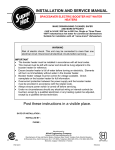
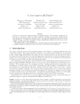
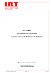
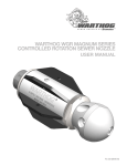
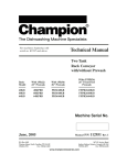
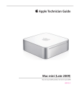
MODEL J
Electric Booster Heater
For Use In Commercial Kitchens And Restaurants
To Supply 180°F Sanitizing Rinse Water
Features
■ Heavy Duty Construction
� All stainless steel tank construction does not require an
internal lining
� ASME Section VIII stamped construction provides for
extended tank life
� Exterior surfaces including the jacket, base and front cover
are all brushed stainless steel for improved appearance and
longevity
■ Advanced Design
� Advanced electronic temperature control with digital display
confirms at a glance proper operation and temperature
setting
� Visual indication of exact set point temperature as well as
fault conditions provides instant feedback
� Electronic leak detection system notifies user in the event of
an internal water leak
� Factory packaged resettable circuit breakers for internal
over current protection save time and money compared to
one shot fuses
� A bronze body (not cast iron) pressure reducing valve is
factory supplied with each booster.
� Designed for ease of service, no electrical component
needs to be removed to replace any other part
Model J
� Screw plug elements with O-ring gasket reduce leakage
problems associated with less reliable and more difficult to
service flange type heating elements.
■
Reliable
� Overall dimensions and connection locations are compatible
with other popular brands to facilitate direct replacement
without modification to the existing plumbing.
� Environmentally friendly CFC/HCFC free closed cell foam
insulation minimizes tank heat loss for maximum operating
efficiency and reduced operating costs
� Full ten (10) year (non pro-rated) tank warranty
ASME
UM
ANSI/NSF 5
ISO 9001:2008
ISO
A Long Lasting Booster Heater
The Hubbell J Model is the longest lasting booster heater
available because it utilizes a heavy duty ASME Section
VIII designed, constructed and stamped all stainless steel
tank which does not require an internal tank lining. Other
manufacturers use a non ASME steel tank with an internal
lining which is easily eroded in high temperature water and
eventually leaves the bare steel tank exposed to the corrosive
effects of water. Once this occurs it is only a short time before
a steel tank will begin to rust, leak, and need replacement.
Hubbell did not stop at improving just the tank design. For
improved appearance and longevity the Hubbell booster
comes standard with a brushed stainless steel outer jacket
and base which is impervious to the corrosive effects of water
and looks great in your kitchen. The Hubbell booster is also
equipped as standard with the advanced functionality of an
electronic temperature controller to provide accurate, reliable
and energy efficient operation while simplifying service work.
The Hubbell booster’s closed cell foam insulation also improves
operating efficiency and reduces the cost of operation. When
you specify and install a Hubbell booster heater, you will have
confidence in knowing that the owner will be provided with a
long lasting and trouble-free source for 180°F water.
The Hubbell Booster: A Leap Ahead
Why Install A
Hubbell Booster Water Heater?
1 Improved Longevity
The Hubbell booster heater is designed to
provide many years of operation. The tank
is all stainless steel construction and is
designed, constructed and stamped in strict
conformance to ASME Section VIII.
2 Lower Operating Costs
The Hubbell booster tank is encapsulated
in environmentally friendly CFC/HCFC free
closed cell foam insulation to minimize
stand-by heat loss. This high quality insulation
reduces heat loss compared to fiberglass type
insulation found in other brands. The result
is that an average Hubbell booster heater
owner can expect to save over 1,400 KW/Hrs
compared to other brands.
3 Reduced Service and Maintenance Costs
Hubbell has greatly simplified booster heater service
and maintenance through numerous advancements in
booster design and controls. The Hubbell controller is
a major step forward with improved ease of use and
service. The digital display provides the owner and
technician with an exact set point temperature as well
as visual error indication. Because the controller can
be set to the exact desired temperature in degrees
– there is no more hotter/colder calibration. It also
includes a leak detection system to notify the user
in the event of an internal leak. For further ease of
service and maintenance, all controls are mounted
such that when a component is removed for service
no other component needs to be removed, and all
sensing functions have been consolidated into one
probe, which can be replaced without draining the
tank. The heating element and sensing probe are
straight thread screw types that utilize an O-ring to
minimize leakage problems as is common with flat
gaskets and NPT connections.
Model J6 Shown
All sensing functions
are integrated into
one probe
Brushed stainless steel
exterior increases life
and looks great
Electronic control
module integrates
all control functions
into one component
Resettable circuit
breakers (on units
over 120 amps)
replace one-shot
fuses
Closed cell foam
insulation lowers
operating costs
ASME stamped all
stainless steel tank
for extended life
Single point power
connection
Leak detection
system notifies
the user if water is
detected inside the
control area
Screw plug
elements
simplify service
Digital display
provides visual
set point and
fault conditions
Note: All components are removable without disturbing any other component
2
Operator controls
are easily accessible
including ON/OFF,
Reset, and Temperature
Adjustment
Model Number Selection Chart With Amperage
Base
Model
J3
J4
J6
J16
J16
with
1-1/2”
inlet
outlet
KW
Rating
Storage
Capacity
Full Model Number Listed by Voltage and Phase
120 V
208 V
240 V
Amperage Draw by Voltage and Phase
480 V
480 V
600 V
120 V
208 V
240 V
480 V 600 V
1Φ
1Φ
3Φ
1Φ
3Φ
3Φ
1Φ
3Φ
1Φ
1Φ
3Φ
1Φ
3Φ
3Φ
3Φ
2.9
J32.9A
—
—
—
—
—
—
—
24
—
—
—
—
—
—
5.7
J35.7A
—
—
—
—
—
—
—
48
—
—
—
—
—
—
—
J39.9RS
J39.9R
—
—
—
—
—
—
48
28
—
—
—
—
10.4
—
J310.4RS
J310.4R
—
—
—
—
—
—
50
29
—
—
—
—
11.4
—
—
—
J311.4S
J311.4T
J311.4T4
—
J311.4T6
—
—
—
48
27
14
11
—
J411RS
J411R
—
—
—
—
—
—
54
31
—
—
—
—
—
—
—
J411RS
J411R
J415T4
—
—
—
—
—
63
36
18
—
27
—
—
J427R
—
J427T
J427T4
—
—
—
—
75
—
65
33
—
1
J61A
—
—
—
—
—
—
—
8
—
—
—
—
—
—
1.5
J61.5A
—
—
—
—
—
—
—
13
—
—
—
—
—
—
2
J62A
—
—
—
—
—
—
—
17
—
—
—
—
—
—
3
J63A
—
—
—
—
—
—
—
25
—
—
—
—
—
—
4
—
J64RS
—
J64S
—
—
J64T4S
—
—
19
—
17
—
—
—
5
—
J65RS
—
J65S
—
—
J65T4S
—
—
24
—
21
—
—
—
6
—
J66RS
J66R
J66S
J66T
J66T4
—
J66T6
—
29
17
25
14
7
6
7
—
J67RS
J67R
J67S
J67T
J67T4
—
J67T6
—
34
19
29
17
8
7
9
—
J69RS
J69R
J69S
J69T
J69T4
—
J69T6
—
43
25
38
22
11
9
10.5
—
J610RS
J610R
J610S
J610T
J610T4
—
J610T6
—
50
29
44
25
13
10
—
J612RS
J612R
J612S
J612T
J612T4
—
J612T6
—
58
33
50
29
14
12
—
J613RS
J613R
J613S
J613T
J613T4
—
J613T6
—
65
38
56
33
16
13
15
—
J615RS
J615R
J615S
J615T
J615T4
—
J615T6
—
72
42
63
36
18
14
18
—
J618RS
J618R
J618S
J618T
J618T4
—
J618T6
—
87
50
75
43
22
17
24
—
J624RS
J624R
J624S
J624T
J624T4
—
J624T6
—
115
67
100
58
29
23
27
—
J627RS
J627R
J627S
J627T
J627T4
—
J627T6
—
130
75
113
65
33
26
30
—
J630RS
J630R
J630S
J630T
J630T4
—
J630T6
—
144
83
125
72
36
29
36
—
J636RS
J636R
J636S
J636T
J636T4
—
J636T6
—
173
100
150
87
43
35
39
—
J639RS
J639R
J639S
J639T
J639T4
—
J639T6
—
188
108
163
94
47
38
40.5
—
J640RS
J640R
J6040S
J640T
J640T6
—
J640T6
—
195
113
169
98
49
39
45
—
—
J645R
J645S
J645T
J645T4
—
J645T6
—
—
125
188
108
54
43
54
—
—
J654R
—
J654T
J654T4
—
J654T6
—
—
150
—
130
65
52
58.5
—
—
J658R
—
J658T
J658T4
—
J658T6
—
—
163
—
141
70
56
1
J161A
—
—
—
—
—
—
—
8
—
—
—
—
—
—
1.5
J161.5A
—
—
—
—
—
—
—
13
—
—
—
—
—
—
2
J162A
—
—
—
—
—
—
—
17
—
—
—
—
—
—
3
J163A
—
—
—
—
—
—
—
25
—
—
—
—
—
—
4
—
J164RS
—
J164S
—
—
J164T4S
—
—
19
—
17
—
—
—
5
—
J165RS
—
J165S
—
—
J165T4S
—
—
24
—
21
—
—
—
6
—
J166RS
J166R
J166S
J166T
J166T4
—
J166T6
—
29
17
25
14
7
6
7
—
J167RS
J167R
J167S
J167T
J167T4
—
J167T6
—
34
19
29
17
8
7
9
—
J169RS
J169R
J169S
J169T
J169T4
—
J169T6
—
43
25
38
22
11
9
10.5
—
J1610RS
J1610R
J1610S
J1610T
J1610T4
—
J1610T6
—
50
29
44
25
13
10
—
J1612RS
J1612R
J1612S
J1612T
J1612T4
—
J1612T6
—
58
33
50
29
14
12
—
J1613RS
J1613R
J1613S
J1613T
J1613T4
—
J1613T6
—
65
38
56
33
16
13
15
—
J1615RS
J1615R
J1615S
J1615T
J1615T4
—
J1615T6
—
72
42
63
36
18
14
18
—
J1618RS
J1618R
J1618S
J1618T
J1618T4
—
J1618T6
—
87
50
75
43
22
17
24
—
J1624RS
J1624R
J1624S
J1624T
J1624T4
—
J1624T6
—
115
67
100
58
29
23
27
—
J1627RS
J1627R
J1627S
J1627T
J1627T4
—
J1627T6
—
130
75
113
65
33
26
30
—
J1630RS
J1630R
J1630S
J1630T
J1630T4
—
J1630T6
—
144
83
125
72
36
29
36
—
J1636RS
J1636R
J1636S
J1636T
J1636T4
—
J1636T6
—
173
100
150
87
43
35
39
—
J1639RS
J1639R
J1639S
J1639T
J1639T4
—
J1639T6
—
188
108
163
94
47
38
40.5
—
J1640RS
J1640R
J1640S
J1640T
J1640T4
—
J1640T6
—
195
113
169
98
49
39
45
—
—
J1645R
J1645S
J1645T
J1645T4
—
J1645T6
—
—
125
188
108
54
43
54
—
—
J1654R
—
J1654T
J1654T4
—
J1654T6
—
—
150
—
130
65
52
58.5
—
—
J1658R
—
J1658T
J1658T4
—
J1658T6
—
—
163
—
141
70
56
64
—
—
J1664R
—
—
—
—
—
—
—
178
—
—
—
—
68
—
—
—
—
J1668T
J1668T4
—
J1668T6
—
—
—
—
164
82
66
9.9
3
Gallons
11.3
15
4
Gallons
12
13.5
6
Gallons
12
13.5
81
16
Gallons
16
Gallons
—
—
J1681R
—
J1681T
J1681T4
—
—
—
—
225
—
195
98
—
86
—
—
J1686R
—
—
—
—
J1686T6
—
—
239
—
—
—
83
88
—
—
—
—
J1688T
J1688T4
—
—
—
—
—
—
212
106
—
Notes:
1.The 6, 7, and 9KW models in 208 and 240 volt can be field converted
from either 1 phase to 3 phase or from 3 phase to 1 phase
2.All 3 phase units are factory wired as a balanced 3 phase unit.
3.Models are also available in 380, 415, 440 and 575 volt.
Please consult factory for exact KW selection in these voltages.
3
Recovery Ratings 1-58.5 kW
KW Rating
Recovery Rate in GPH at °F Temperature Rise (∆T)
20° ∆T
30° ∆T
40° ∆T
60° ∆T
70° ∆T
80° ∆T
110° ∆T
140° ∆T
1
1.5
2
3
4
5
6
7
9
10.5
12
13.5
15
18
24
27
30
36
39
40.5
45
54
58.5
20
31
41
61
82
102
123
143
184
215
246
276
307
368
491
553
614
737
798
829
921
1105
1198
14
20
27
41
55
68
82
96
123
143
164
184
205
246
328
368
409
491
532
553
614
737
798
10
15
20
31
41
51
61
72
92
107
123
138
154
184
246
276
307
368
399
415
461
553
599
7
10
14
20
27
34
41
48
61
72
82
92
102
123
164
184
205
246
266
276
307
368
399
6
9
12
18
23
29
35
41
53
61
70
79
88
105
140
158
175
211
228
237
263
316
342
5
8
10
15
20
26
31
36
46
54
61
69
77
92
123
138
154
184
200
207
230
276
299
4
6
7
11
15
19
22
26
33
39
45
50
56
67
89
100
112
134
145
151
167
201
218
3
4
6
9
12
15
18
20
26
31
35
39
44
53
70
79
88
105
114
118
132
158
171
64
68
81
86
88
1310
1392
1658
1761
1802
873
928
1105
1174
1201
328
348
415
440
450
238
253
301
320
328
187
199
237
252
257
Recovery Ratings 64-88 kW
655
696
829
880
901
437
464
553
587
601
374
398
474
503
515
Formulas To Solve For:
Recovery
GPH x Electrical
OF ∆T x 0.00244 = KW
KW x 410 ÷ GPH = F ∆T
O
KW x 410 ÷ F ∆T = GPH
Note:1 KW will heat 4.1 GPH at a 100OF ∆T
O
KW x 1000 ÷ 1.73 = Amps 3 Phase Φ
Volts
KW x 1000 = Amps 1 Phase Φ
Volts
Metric Conversion
Liters x 0.2641 = Gallons
°F = (°C x 1.8) + 32
kPa x 0.1456 = psi
Gallons x 3.79 = Liters
°C = (°F - 32) x 0.556
Lbs x 0.4536 = Kg
Gallons x 0.003785 = m3
psi x 0.06896 = Bar
Kg x 2.2 = Lbs
m3 x 264.2 = Gallons
Bar x 14.5 = psi
Watts/Sq.Cm. x 6.4 = Watts/Sq.In.
1°F ∆T = 1.8°F ∆T
psi x 6.86 = kPa
Watts/Sq.In. x 0.155 = Watts/Sq.Cm.
Voltage De-Rating Factors
Rated Voltage Applied Voltage
600
600
480
480
240
240
4
575
550
460
440
230
220
KW De-Rating Factor
92%
84%
92%
84%
92%
84%
When the actual supply voltage (applied voltage) is different
than the booster design voltage (rate voltage) the resulting KW
output will be affected. Please see the chart for typical voltage
de-rating factors, or use the following formula:
Applied Votage2 x Rated KW = KW output at applied voltage
Rated Voltage2
Model J6 - (1 to 18 kW) Dimensions
13"
2"
21"
7 7/8"
13 3/4"
9 1/2"
Shipping Weight: 95 lbs.
25" Approx.
6 1/2"
Outlet 3/4"
MNPT
2 1/4"
Inlet 3/4"
MNPT
6"
2 1/2"
1 1/2"
Relief
Valve
10"
Rear View
14 1/8"
5 3/8"
Left Side View
2 1/2"
Knockouts: Left Side And Bottom
3/4" X 1" X 1-1/4"
3"
Bottom View
Model J6 - (24 to 58.5 kW) Dimensions
18"
11 1/2"
2"
3"
2"
29 1/8" Approx.
Outlet
3/4"
MNPT
24"
12"
7 7/8"
6"
Shipping Weight: 110 lbs.
Relief
Valve
1 1/2"
Inlet
3/4" MNPT
15"
Rear View
3 1/4"
17"
5 5/8"
Left Side View
3 1/4"
Knockouts: Left Side - (1) 1-1/2" X 2"
Bottom - (2) 1/2" and (1) 1-1/2" x 2"
3 1/4"
2 1/2"
1 1/2"
Bottom View
Model J16 - (1 to 58.5 kW) Dimensions
3 1/2"
2 5/8"
Front
3"
9 3/4"
Relief
Valve
3/4" MNPT
Inlet
3/4" MNPT
Outlet
Nipple
23"
25 3/8"
16 1/2"
9 3/4"
Shipping Weight: 160 lbs.
2"
2"
6"
2"
23 1/2"
2 5/8"
Bottom View
Right Side View
Knockouts: Left Side - 1-1/2" X 2"
Bottom - 1-1/2" X 2" and 3/4" X 1" X 1-1/4"
5
Model J16 - (64 to 88 kW) Dimensions
3 1/2"
2 5/8"
1 1/2" MNPT
Outlet
Front
3"
1" NPT
Relief
Valve
9 3/4"
1 1/2"
MNPT
Inlet
25 3/8"
23"
16 1/2"
9 3/4"
Shipping Weight: 195 lbs.
2"
23 1/2"
6"
1 1/2" MNPT
Inlet
2 5/8"
Bottom View
Right Side View
Knockouts: Left Side - 1-1/2" X 2"
Bottom - 1-1/2" X 2" and 3/4" X 1" X 1-1/4"
Model J3 - (2.9 to 11.4 kW) Dimensions
13 1/4"
3/8"
12 1/2"
Relief
Valve 9"
3/8"
3"
11 3/4"
5 1/2"
4 7/8"
5 7/8"
13"
4 1/2"
6"
Front View
Shipping Weight: 46 lbs.
Note: Shown with optional legs
Ø 5/16" Mounting
Holes (4 Places)
Top View
3/4" FNPT Outlet
1/2" (0.84) KO
4 1/4"
1 1/4" 1 1/2"
3/4" FNPT Inlet
1/2"
1" x 3/4" x 1/2"
knockout
Bottom View
Model J4 - (11.3 to 27 kW) Dimensions
26 3/4" (Approx.)
23 1/16"
20 5/8"
10 13/16"
3/4"
6"
3 17/32"
3 3/4"
1 1/2" x 1" x 3/4"
Knockout
Right Side View
1 1/2" x 1" x
3/4" Knockout
3 17/32"
Bottom View
6
1 1/8"
2 3/4"
Relief
Valve
Inlet 3/4"
MNPT
(4) 3/8" Holes
(Both Sides)
for LH or RH
Mounting
5 13/32"
6" 11 7/16"
7"
1 9/16"
Shipping Weight: 80 lbs.
Note: Shown with optional legs
Outlet 3/4" 2 1/4"
MNPT
2 15/16"
Rear View
Typical Installation Diagrams
Typical J6 Plumbing Connections
(Rear View)
Temperature/
Pressure Gauge
(Optional)
Water Treatment
Brass Pressure
T&P Relief Valve
System
Reducing Valve with
(Optional)
Built-In Bypass
Shock
Absorber
(Optional)
3/4" Dielectric
Union
Temperature/
Pressure Gauge
Outlet
Gate
Valve
(Not Supplied)
T&P Relief Valve Piping
(Air Gap Must Conform To Code)
Inlet
3/4" Dielectric
Union
Drain Valve
(Not Supplied)
Typical J16
Plumbing
Connections
(Front View)
T&P Relief Valve
Temperature/
Pressure
Gauge
Water
Treatment
System
(Optional)
Gate Valve
(Not Supplied)
T&P Relief Valve Piping
(Air Gap Must Conform To Code)
Brass
Pressure
Reducing
Valve with
Built-In
Bypass
Temperature/
Pressure Gauge
(Optional)
Shock
Absorber
(Optional)
Outlet
Inlet
3/4" Dielectric
Drain Valve
Union (Optional) (Not Supplied)
3/4" Dielectric
Union
Plumbing Notes:
1.Dielectric unions as supplied must be installed in the inlet and outlet piping to prevent electrolysis.
2.No check valve may be installed in the supply line to the booster.
3.All shut off valves must be gate or ball valves - not globe valves.
4.The brass pressure reducing valve with built-in bypass is adjustable from 25 to 75 psi.
5.To minimize heat loss and maximize efficiency, hot water piping should be insulated.
7
Typical Installation Diagrams
Typical J4 Plumbing
Connections
(Rear View, shown
with optional legs)
Brass Pressure
Reducing
Water Treatment
Valve with
System
Built-In Bypass
(Optional)
(Optional)
Temperature/
Pressure Gauge
(Optional)
T&P Relief Valve
Temperature/
Pressure Gauge
(Optional)
3/4" Dielectric
Union
(Optional)
Shock
Absorber
(Optional)
Outlet
Gate
Valve
(Not Supplied)
T&P Relief Valve Piping
(Air Gap Must Conform To Code)
Inlet
3/4" Dielectric
Union (Optional)
Drain Valve
(Not Supplied)
Legs (Optional)
Temperature/
Pressure Gauge
(Optional)
Typical J3 Plumbing
Connections
Shock
Absorber
(Optional)
Outlet
(Front View, shown
with optional legs)
3/4" Dielectric
Union (Optional)
T&P Relief Valve
Temperature/
Pressure
Gauge
(Optional) Brass
Pressure
Water
Reducing
Treatment
Valve with
System
Built-In
(Optional)
Bypass
(Optional)
Gate Valve
T&P Relief Valve Piping
(Air Gap Must Conform To Code)
(Not Supplied)
Legs (Optional)
Inlet
3/4" Dielectric
Union (Optional)
Drain Valve
(Not Supplied)
Plumbing Notes:
1.Dielectric unions are recommended for installation in the inlet and outlet piping to prevent electrolysis.
2.No check valve may be installed in the supply line to the booster.
3.All shut off valves must be gate or ball valves - not globe valves.
4.The brass pressure reducing valve with built-in bypass is adjustable from 25 to 75 psi.
5.To minimize heat loss and maximize efficiency, hot water piping should be insulated.
8
J Model Standard Accessories
J6 and J16 Boosters
J4 Boosters
� T&P Relief Valve
� Brass pressure reducing valve
� (4) NSF approved plastic legs
� (1) Combination temperature
J3 Boosters
with built-in bypass
and pressure gauge
� (2) Dielectric Unions
� T&P Relief Valve
� Side mounting bracket for securing
booster to left or right hand side of
dish machine
� T&P Relief Valve
� 24 volt booster heater interlock adapter
Note: Any and all optional accessories for a Hubbell booster heater must be called out in the written specifications.
A model number in and of itself does not reflect any optional accessoties selected.
Optional Accessories
7.Water Treatment System: Provide superior
1.Slide Brackets: Available for the J6 model
mineral scale prevention and corrosion control
by feeding a special blend of scale control
compounds into the hot water stream before
the booster. The in-line system to include a
clear cartridge housing to allow an operator to
view the cartridge and determine when it needs
replacement without the need to open the
system.
only, these brackets allow for mounting the
booster heater under a counter. See slide
bracket diagram for details.
2.Shock Absorber: Reduce the harmful
pressures resulting from quick closing
dishwasher solenoid valves by installing a
shock absorber between the booster and the
dishwasher.
8.Alternative Voltages: Hubbell booster heaters
3.Tamper Resistant Package: For prison
are available in alternate voltages including 380,
415, 440 and 575 volt. Please contact factory
for kW selection.
and other secure facilities a tamper resistant
package is available with all hardware tamper
resistant type. Includes standard plastic legs
unless otherwise specified.
9.Low Temperature Interlock: This device
4.Protective Cover: Keep your Hubbell booster
free from dirt, debris, chemicals and excessive
water with this removable form fitted protective
cover. Velcro fasteners make it easily installed
and simple to remove when service is required.
Clear window allows visibility of Hubbell booster
digital display.
5.Alternate Legs: Please specify type: Nickel
plated die cast, stainless steel, stainless steel
with flanged base for floor mounting.
6.24 Volt Heater Interlock Adapter: An optional
plug adapter that interlocks the heater via a
24-Volt signal through the J1 connector on the
control board (standard on the J3).
is built into the booster and monitors water
temperature and will trip an SPDT relay when
water temperature drops below a set point
(150 - 180°F) thereby preventing final rinse from
activating.
10.Remote Alarm Adapter: This device installs
into the Hubbell controller and provides
remote alarm capability to indicate a reset fault
condition. Common/N.O./N.C. rated 220 VDC,
250 VAC, 2 amp max.
11.Remote Control Panel: This device allows
you to install the booster in one location and
have complete control of it (on/off, temperature
adjustment, reset and temperature indication)
from another location (200 feet maximum).
Remote control panel is 5" x 2" x 3" and
NEMA 4 rated.
J6 Slide Bracket Detail
“A” Dimension
4 To 18 Kw: 17"
24 To 58.5 Kw: 22"
A
Weld Slide Rail To
Bottom Of Dishtable
Attach Slide Bracket
Angle To Heater Jacket
9
Water Quality Requirements
Recommended water hardness is 4 to 6 grains of hardness per gallon (GPG). Water hardness
above 6 GPG should be treated by a water conditioner (water softener or in-line treatment). Water
hardness below 4 GPG also requires treatment to reduce potential corrosion. Excessive GPG will
result in higher operating and maintenance costs and will reduce product longevity.
Chlorides must not exceed 50 parts per million (ppm). Excessive chlorides will result in metallic
corrosion and will reduce product longevity.
Water treatment has been shown to reduce costs associated with deliming the booster as well
as reducing metallic corrosion. Product failure caused by these conditions is not covered under
warranty. See warranty for complete details.
Booster
Sizing
a Low
Temp
Dishmachine
Booster
Sizing
for afor
Low
Temp
Dishmachine
Chemical low-temp dishwashers are most
effective when supplied with 140°F hot water. This
water temperature may not be available due to an
undersized primary water heater or local safety
code. Hubbell J model boosters can operate as
a pre-heater for chemical low-temp dishwashers
to provide an adequate supply of 140°F hot water
for proper operation. For temperatures other than
the factory setting of 185°F, simply set the digital
display to your desired temperature.
To properly size a Hubbell booster heater for
low temp use:
1.Determine the required temperature rise; the
difference in temperature between your supply
water temperature to your booster and your
desired hot water temperature out of the booster.
2.Determine the water usage gallons per hour (GPH)
by consulting the dishwasher data plate, literature
or NSF listing.
3.Select the appropriate kW based on 1 and 2 above
using either the formula below or the Recovery
Rating Chart on page 4.
Booster Sizing Formula
Formula to Determine KW:
Required Variables:
A . Water usage in GPH
GPH x
B. Supply water temp in °F
C. Desired water temp in °F
D. Calculate the ∆T (temp rise)
by subtracting C - B in °F
10
°F ∆T x 0.00244 = KW
Booster Heater Dishwasher Sizing Chart
40 °F Rise
Dishwasher
Model Number
ADAMATION
CSL-1390, CA-2, CA-3, CA-4, SLAP 44
CA, CA-1
6 Gallon
16 Gallon
70 °F Rise
6 Gallon
16 Gallon
Model J6 Model J16 Model J6
Model J16
40 °F Rise
Dishwasher
Model Number
INSINGER
J639
J654
J1639
J1654
(2) J636
(2) J645
(2) J1636
(2) J1645
ALVEY
FLC-10, SL-2S
J166
FLC-12, CL-1, CL-1Turntable, SA-5A
J167
FL-2S
J169
KS-70, KS70M SB
J169
SL-2D
J1613
FLC-36
J1615
KS-88
J1618
KS-70-N, KS-88-N
J1639
AMERICAN DISH SERVICE
HT-25
J67
J167
J612
ACD-44, ADC-66
J612
J1612
J624
BLAKESLEE
UC-21
J66
J166
J612
D-8
J69
J169
J613
Series “R” & “ F” -CC, -EE, -LL, -MM,
J613
J1613
J624
-LLL, -MMM, -PCC, -PEE, -PLL, -PMM
Series XF-LL, XF-PLL, XF-MM, XF-PMM,
J618
J1618
J630
XF-EEE, XF-LLL, XF-MMM
DD-8
J618
J1618
J630
Series R-L, R-PL, R-M, R-PM, F-L, F-PL,
J636
J1636
J654
F-M, F-PM (single tank)
Series XF-L, XF-PL, XF-M, XF-PM,
(2) J636
(2) J1636
Series XF-PEE, XF-PLL, XF-PMM,
J645
J1645
(2) J630
XF-EEE, XF-LLL, XF-MMM (multi tank)
NOTE: FA (Flight-A-Round) and RA (Rack-A-Round) use comparable “F” listing.
CHAMPION
U-H1, UH-200, UH-200B, U-HB
J64
J166
J66
UL-150
J64
J166
J67
UH-150, UH-150B, UH-100, UH-100B,
J65
J166
J69
DHB-VS
D-H1, D-HB
J66
J166
J612
D-H1T, D-HBT
J67
J167
J612
PP-28
J69
J169
J615
D-H1C, D-H1TC
J69
J169
J618
66 WSPW, 44-WS, 66-WS
J613
J1613
J624
UC-CW6-WS
J624
J1624
J636
US-CW8-WS
J624
J1624
J639
44, 66 PW, 70FFPW, 80HDPW, 54,
76PW, 80FFPW, 90HDPW, 64, 90FFPW,
J624
J1624
J645
100HDPW, 86PW
40-KB, 44-KB-2-2, 40-KFWB, 40-KPRB,
40-KPRB-2-2, 40PRB-2-3, 60-KB,
60-KB-2-2, 60-KFWB, 60-KFWB-2-2,
J630
J1630
J654
60-KPRB, 60-KPRB-2-3, 64KB, 64-KB
Corner, 64-KPRB Corner, 64-KPRB, 64KPRB Corner, 64 Modular, 86 Modular
44-KB, 44-KB Corner, 44-KPRB,
44-KPRB Corner, 54-KB, 54-KB Corner,
J636
J1636
J658
54-KPRB, 54-KPRB Corner, 44 Modular,
66 PW Modular
UC-CW4
J636
J1636
(2) J636
UC-C
J645
J1645
(2) J636
UC** Series 6’ Center
J645
J1645
(2) J639
W-6-WS
J645
J1645
(2) J645
CMA DISH MACHINES
CMA-180
J67
J167
J612
CMA-44H with tank heater, CMA-66H
J636
J1636
J645
HOBART
AM-15F
J64
J166
J66
LXiC, LXiGC, LX-18C, LX-30C, LX-40C
J64
J166
J67
LX-30, SR24, SR24H
J64
J166
J67
LX-18
J65
J166
J69
AM-15, AM-15T
J65
J166
J69
WM-5C
J66
J166
J69
WM-5 (Without Sump Heater)
J67
J167
J612
AM-14T, AM-14F, AM-14TC
J67
J167
J612
AM-14, AM-14C
J69
J169
J612
AM-12, AM-12C*
J69
J169
J618
UW-50
J1615
Opti-Rinse Models: C44A, CRS-66A,
CCS-66A, CPW-80A, C54A, CRS-76A,
CCS-76A, CPW-90A, C64A, CRS-86A,
J615
J1615
J627
CCS-86A, CPW-100A, C88A, CRS-110A,
CCS-110A, CPW-124A
C-54A, CRS-76A, CPW-90A, CCS-76A
J639
J1639
(2) J636
C-44A, CRS-66A, CCS-66A, CPW-80A,
J630
J1630
J654
C-64A, CRS-86A, CCS-86A CPW-100A
C-88A, CRS-110A, CPW-124A, CCSJ636
J1636
J654
110A
Opti-Rinse Models: C44AW, CRS-66AW,
J69
J169
J615
CCS-66AW, CPW-80AW
C-44AW, CRS-66AW, CPW-80AW,
J612
J1612
J624
CCS-66AW
C-44, CRS-66, CPW-80
J636
J1636
J654
C-54, CRS-76, CPW-90
J654
J1654
(2) J639
C-64W, CRS-86W, CPW-100W, C-88W,
J624
J1624
J636
CRS-110W, CPW-124W, CCS-86W
C-64, CRS-86, CPW-100
J645
J1645
(2) J636
FT800W, FT-900W
J624
J1624
J639
FT-600, FT-700
J654
J1654
(2) J639
FT800
J639
J1639
(2) J639
FT-900
J636
J1636
J658
FT800S, FT-900S
J639
J1639
(2) J636
Opti-Rinse Models: FT900-10-FPM,
J624
J1624
J639
FT900-12-FPM, FT900-6-HTS
Opti-Rinse Models: FT900S
J624
J1624
J624
UTW-28, UTW-28C
J1618
NOTE 1. FRC and FR (Fast Rack Series) use comparable “C” line listing.
NOTE 2. Model AM-12 with serial no. 12-067-357 or below and model AM-12C with
serial no. 12-067-537 or below require slightly larger booster heater than listed.
NOTE 3. C models with serial no. 85-1041605 or greater use Opti-Rinse
J169
J1612
J1613
J1615
J1618
J1627
J1630
J1612
J1624
J1612
J1613
J1624
J1630
J1630
J1654
(2) J1630
J166
J167
J169
J1612
J1612
J1615
J1618
J1624
J1636
J1639
J1645
J1654
J1658
(2) J1636
(2) J1636
(2) J1639
(2) J1640
J1612
J1645
J166
J166
J167
J169
J169
J169
J1612
J1612
J1612
J1618
J1624
J1627
(2) J1636
J1654
J1654
J1615
J1624
J1654
(2) J1639
J1636
(2) J1636
J1639
(2) J1639
(2) J1639
J1658
(2) J1636
J1639
J1624
J1636
JACKSON
6 Gallon
16 Gallon
70 °F Rise
6 Gallon
16 Gallon
Model J6 Model J16 Model J6
Model J16
Commander 18-5, 18-5H, Ensign 40-2
Admiral 44-4, 66-4
Speeder 64, 86-3, Century (all)
Trac 321, Trac 321-2/RPW
Trac 878
Clipper (all), R106-2, Super 106-2
Defender
Master (all)
CA-3
DA-3
J66
J624
J624
J627
J624
J627
J636
J636
J166
J1624
J1624
J1627
J1624
J1627
J1636
J1636
J169
(2) J169
J612
J636
J645
J645
J636
J645
J654
J658
J1612
J1639
J1645
J1645
J1636
J1645
J1654
J1658
J1624
(2) J1624
JPX-140, JPX-160, JPX-200, JPX-200/2,
TSC-44, TSC-66
H-24, HZ-24, JP-24, JPX-300H,
JPX-300HN, JPX-300N, M-24BF
JP-24B, JP-24F, JP-24BF
24B Series
10AB, 10APRB
200, Huey 165, Supra-Q2020
100B, 100PRB, 150B, 150PRB
Tempstar SDS
J64
J166
J64
J166
J64
J166
J65
J166
J64
J166
J66
J166
J66
J166
J66
J64
J65
J69
J69
J612
J166
J166
J166
J169
J169
J1612
J66
J166
J612
J1612
10A, 10APRB, 10APRB-M, 10U, 300X,
300XN, ES-18, ES-18HT, E-xxion, TS-57,
Tempstar, Tempstar 300N, Tempstar
300X, Tempstar 300XG, Tempstar GPX
Inferno, Omega HT
J67
J167
J612
J1612
PH-HT, Performer, TempStar HH,
J67
J167
J613
J1613
TempStar HH/GPX, TempStar HH/S
200B
J66
J166
100
J612
J1612
J624
J1624
150
J612
J1612
J618
J1618
TS-44, TS-66
J624
J1624
J636
J1636
AJ-64, AJ-86, AJ-100, JFT, JFT Flight
J624
J1624
J639
J1639
Type, JFT-G, JFT-S
ES-8000, PA-C4, WH-44, WH 66
J624
J1624
J645
J1640
64CE, 86 CERPW
J627
J1627
J639
J1639
AJ-54, AJ-76, AJ-90
J630
J1630
J654
J1654
44CE*, 66 CERPW
J630
J1630
J654
J1654
54CE, 76 CERPW
J636
J1636
(2) J630
(2) J1630
AJ-44, AJ-66, AJ-80, ES-4400, ES-6600
J624
J1624
J645
J1645
(ECOLAB/JACKSON)
NOTE 1: Model 44CE with serial no.1999 or below requires larger booster than listed.
KNIGHT EQUIPMENT
KLE-112-HL
J67
J167
J612
J1612
MEIKO
K-44, K-66, K-80
J624
J1624
J636
J1636
K-54, K-76, K-90, K-64, K-86, K-100
J624
J1624
J645
J1645
METALWASH/INTEDGE
FW4
J612
J1612
J618
J1618
RS-30A, RS-28L
J1615
J1624
RT-74, RT-60, RT-42B, RT-42BC
J1627
J1640
RS-2R
J1630
J1645
STERO
SCT-44-10-LW, SCT-44-LW,
SCT-66S-LW, SCT-76S-LW,
J612
J1612
J624
J1624
SCT-76SC-LW, SCT-90S-LW
SC-1-2-4-LW, SC-1-6-4-LW,
SC-1-6-4-LW, SC-2-4-LW, SC-5-6-4-LW,
J624
J1624
J645
J1645
SC-6-4-LW
SCT-64, SCT-86S, SCT-94S,
J624
J1624
J639
J1639
SCT-94SC
SCT-108S, SCT-108SC, SCT-76,
J627
J1627
J654
J1654
SCT-94SM
SC-6-4, SCT-44, SCT-44-10,
SCT-44-10, SCT-66S, SCT-76S,
J630
J1630
J654
J1654
SCT-90S
SCT-120S, SCT-120SC, SCTJ636
J1636
J658
J1658
120SM, SCT-150SM
STW-110, SC-1-2-7-4, SC-1-6-3-4,
SC-1-6-7-4, SC-2-7-4, SC-5-2-7-4,
J639
J1639
(2) J636
(2) J1639
SC-5-6-3-4, SC-5-6-7-4, SC-6-34, SC-6-7-4
SC-1-2-4, SC-1-6-4, SC 2-4, SCJ645
J1645
(2) J636
(2) J1645
5-2-4, SC-5-6-4
SCT-44-10-SC-1-3-4, SCT-4410-3-4, SCT-44-SC-1-3-4, SCTJ645
J1640
(2) J636
(2) J1636
44-SC-3-4, SCT-54-SC-1-3-4,
SCT-54-SC-3-4, SCT-76S-SC-3-4
STPC (Four Tank)
J624
J1624
J639
J1639
STPCW (Four Tank)
J624
J1624
J645
J1640
STPC
J627
J1627
J654
J1654
STPCW
J636
J1636
(2) J630
(2) J1630
SCBT
J645
J1640
(2) J636
(2) J1636
SF-1RA, SC20-1
J67
J167
J612
J1612
SF-2RA, SF-2DRA, SD-2RA,
J612
J1612
J618
J1618
SDRA, SDRA-PACK
SCT-54, SCT-76SM
J636
J1636
J658
J1658
SCT-76, SCT-80, SCT-94, SCTJ645
J1645
J658
J1658
108, SCT-120
U-31-A, U-31-AC
J1618
J1636
U-31-A2
J645
J1645
(2) J636
(2) J1636
STBUW-14
J658
J1658
(2) J654
(2) J1654
SC-2-3-4, SC-5-2-3-4
J630
J1630
(2) J627
(2) J1627
SC20-2
J612
J1612
J624
J1624
SC-2-8, SC-2-9, SC-1-2-8, SC-5-6-8,
SC-6-8, SC-6-9, SC-1-6-8, SC-5-6-9,
SC-5-2-9, SC-1-6-9, SC-5-2-8
J618
J1618
J636
J1636
This selector chart is based upon 40 degree F and 70 degree F temperature rises,
20psi flow pressure and minimum rinse cycle timer setting in NSF listing.
All booster heaters are rated at 100% of the capacity of the dishwasher as
recommended by the National Sanitation Foundation. Where make-up water for
the wash tank is provided from the final rinse supply, chart recommendations are
based upon this additional demand (not exceeding 2 GPM) as required by NSF.
11
Master Specification: Model J
JOB NAME
CONSULTANT / SPECIFIER
REPRESENTATIVE
DEALER / SERVICE AGENT
Provide a quantity of electric booster water heater(s) Model No. as manufactured by Hubbell. The pressure vessel shall be all stainless steel welded construction and shall bear the ASME
Section VIII stamp. The tank shall be insulated with CFC/HCFC free high efficiency closed cell foam insulation to reduce
standby heat loss. To minimize operating expenses, heat loss shall not exceed 425 btu/hr.
The booster shall be listed and approved in accordance with UL Sanitation (NSF5) and UL1453. All controls shall be
built-in and factory wired. The booster shall include internal resettable circuit breakers in lieu of one-shot power fuses for
over current protection when required. The immersion heating elements shall be high quality screw plug type with O-ring
gasket to ensure leak free long life service. All temperature, hi-limit, and low water operating functions shall be controlled
by an electronic digital display solid state device that shall provide the operator with visual indication of temperature
setting and fault conditions. For ease of service for any replaceable component, the positioning of all components shall
be such that to remove any component does not require the removal of another component.
The entire exterior of the booster heater including the base, jacket and front cover shall be brushed stainless steel for
maximum corrosion resistance, longevity and appearance.
The booster heater shall include an ASME/CSA rated combination temperature and pressure relief valve, 6" adjustable
NSF plastic legs (Optional Specification: slide brackets on J6 model only), bronze body pressure reducing valve with builtin bypass, and one indicating temperature and pressure gauge.
The entire pressure vessel shall be provided with a full ten (10) year Non Pro-Rated tank warranty. The entire booster
heater including all components shall be provided with a one-year warranty including parts and labor.
Sales and Service Network
An extensive network of authorized Hubbell Service Agents, Dealers, and Sales Representatives stand ready
to support the needs of the Food Service Industry and to ensure that Hubbell Customers are provided with the
highest quality in customer case and service.
Access Hubbell’s website for a complete listing of authorized Hubbell Service Agents, Dealers, and Sales
Representatives.
Complete Inventory Ready to Ship
Hubbell is committed to serving the needs of the Food Service Industry, including having the complete line of
Hubbell booster heaters ready to ship the same day when an order is received by the factory by 12:00pm eastern
time. Hubbell’s investment in a state-of-the-art production facility and an extensive on-hand inventory ensures that
our Food Service Customer’s needs are met in a timely fashion.
ISO 9001:2008
ISO
Made in the U.S.A.
Committed to continuous improvement...
Continuing research results in product improvement; therefore specifications are subject to
change without notice. For the most updated information, consult the factory directly.
The Electric Heater Company
■
P.O. Box 288 ■ Stratford, CT 06615-0288 ■ Phone: 203-378-2659
[email protected] ■ www.hubbellheaters.com
■
Fax: 203-378-3593