1
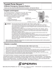
9200 SERIES
USERS MANUAL
9200-0289-001
9200-0289-002
9200-0290-001
LCD Monitor User Guide
150-VFX9-001
Table Of Contents
Section 1 Display Setup
Product Safety Precautions
Included Parts
Connecting Your Display
Section 2 Getting Started
Adjusting the Display
Keyboard Layout & Functions
Section 3 Touch Screen Set up
Introduction to Touch Screens
Touch Screens Provided
Touch Screens and Special Drivers
Section 4 Mounting Istructions
VESA Wall Mounting
Section 5 Trouble Shooting Tips
Section 6 Cleaning and Maintenance
Section 7 Appendices
A - Video Pin Assignments
B - RS-232 Pin Assignments
C - 9200 Specifications
150-VFX9-001
2
1
Section
Display
Setup
Product Safety Precautions
•
•
•
•
•
•
•
•
Do not attempt to service this display yourself. The rear chassis has a seal so that nonqualified personnel will not expose themselves to dangerous voltages or other risks.
To protect from electrical shock, unplug the display power supply from the wall before
moving.
Do not use this display near water
Do not place any heavy objects on the power cords. Damage may cause electrical
shock.
Unplug the power supply from the wall or unit if one of the following conditions exists.
o Power cord or plug is damaged or frayed.
o Liquid is spilled into the display or the display is exposed to rain or water.
o The display does not operate normally when the operating instructions are
followed.
o The display has been dropped or the enclosure has been damaged.
o The display exhibits a distinct change in performance, indicating a need for service.
Ensure that sufficient space is available around the display to provide air circulation for
cooling.
Ensure that the ambient air temperature will not exceed the specified maximum
temperature.
Do not expose the display to direct sunlight or heat.
Included Parts
Open shipping container and lay all components on a flat clean surface.
Your LCD monitor package will consist of the primary components listed below:
• LCD Monitor
• 6 ft Video Cable
• 6 ft AC Power Cord
• 6 ft RS-232 Touch Interface Cable
• Screws for Mounting to VESA Stand or Arm
• Users Manual
Connecting Your Display
1. Connect all cables to the computer first. This includes the VGA cable and Serial RS-232 touch screen
connection.
150-VFX9-001
3
2. After connecting the cables between the LCD monitor and the computer, connect the supplied AC
Power Cord to a suitable power source.
3. The LCD will immediately power up.
4. If your computer is off, turn on your computer or video source.
5. Your display should now operate as a normal computer display.
Note: If for any reason the display goes blank and/or displays “Out of Range” or “No Input Signal” message
on the screen, your computer or video source may be putting out a signal that is incompatible with the LCD
monitor.
Below are the most common reasons a display may not operate correctly:
1. The resolution is to high or low for the LCD or wrong sync signal configuaration is provided.
2. The power source is incorrect, or there is no power. Check if the rear LED is ON or blinking. If the
LED is not lit, check to be sure there is power to the unit.
3. The unit is malfunctioning. If you believe this to be true, disconnect the video cable from the rear
of the LCD and connect to a known good display. If an alternate display operates correctly, and
the video is in a compatible range then contact Aydin Displays, Inc. technical support.
150-VFX9-001
4
2
Getting
Started
Section
Adjusting the Display
The LCD display has an embedded microprocessor in the converter card which is the
electronics that drives the LCD. In most cases the unit will require very little, if any, user
intervention to operate correctly – that is to produce a sharp stable picture. The
microprocessor in the display has the capability to adjust itself to the computer to which it is
attached. If the picture is not satisfactory, the first step is to allow the unit to attempt to adjust
itself to your computer.
The membrane keypad used for adjusting the display is below:
Keyboard Layout & Function
1. With the OSD off, push the Menu button to activate the main OSD menu.
2. Use the Up/Down buttons to move from one function to another. As you move from
one icon to another, the function name changes to reflect the function or group of
functions represented by the icon.
3. Press the Set button once to activate the highlighted function. Use the Up/Down
buttons to select the function.
4. After selecting a function, use the – or + butttons to make necessary adjustments.
The setting bar moves and the numeric value indicator changes to reflect the
adjustment.
NOTE: The numeric value indicator is provided as a point of reference only and has
no reference to a real measurement.
5. Push the Menu button a couple of times to return to the main menu to select another
function or to exit from the OSD.
150-VFX9-001
5
150-VFX9-001
6
150-VFX9-001
7
150-VFX9-001
8
3
Touch Screen
Setup
Section
Introduction to Touch Screens
The 9200-0289-001 and –002 are equipped with an IR (Infrared) Touch System designed to
operate in a DOS environment. This IR screen replaces the old Carroll Touch Systems. The
9200-0290-001 is equipped with a SAW (Surface Acoustical Wave) Touch System OEM
designed for an OEM and equipped with a serial RS-232 interface with special firmware.
Touch Screens Provided
IR
RS-232
9200-0289-001
IR
RS-232
9200-0289-002
SAW
RS-232
9200-0290-001
Touch Screen and Special Drivers
Since these touch systems are for specific DOS based systems, the drivers are embedded in
OEM’s equipment and not supplied by Aydin Displays, Inc.
150-VFX9-001
9
4
Section
Mounting
Instructions
VESA Wall Mounting Procedure
The monitor is a self conatined rugged, industrial aluminum metal enclosure.
The rear of the unit has 4 100mm M4 holes for mounting hardware from a external
arm or stand or special fixture.
If you are using Aydin’s Table Stand P/N 132-7004-001, proceed as follows:
1. Position the monitor on the face, being careful not to scratch the front.
2. Attach the 100mm bracket supplied with stand with M4 x 12 screws kits.
3. Install the arm based on the instructions.
4. Attach the power, video and touch screen cables to the under side of the monitor.
150-VFX9-001
10
150-VFX9-001
11
150-VFX9-001
12
150-VFX9-001
13
5
Section
No picture
Troubleshooting
Tips
The signal cable should be properly connected to the
Display and Computer.
Try disconnecting the video cable from the display and
connecting to another display if available to confirm the
presence of proper video.
Make sure power is connected to the proper AC source.
Make sure the resolution mode is supported by the display
and check display settings of the PC
Confirm that the video cable is not defective.
Image persistence
Image persistence occurs when a ghost of an image remains
on the screen after the screen image has been changed.
Unlike a CRT monitor, an LCD monitor’s image persistence is
not permanent. To erase an image ghost, turn the monitor off
for several hours. What happens is that after extened periods
of operation the liquid crystals “set”. To avoid this condition,
install a screen saver progam on the computer.
Picture quality & image
stability
Check video cable for proper grounding and shielding.
Check the signal source for proper signal.
Check for proper adjustment of the Phase and Frequency
controls.
Check for proper recommended signal timing.
Green LED not lit
150-VFX9-001
Check for proper power and power connections.
14
Display image is not
properly sized
Press the “Select” button to Auto Adjust the display.
Adjust the Vertical and Horizontal size controls via the OSD
(reference OSD Adjustments).
Ensure that a supported mode is selected on the display card
or system being used. Consult the display card or system
manual for proper video.
Image will not adjust
Video timing outside of range.
Use the on-screen menu to adjust the Clock Setting.
Make sure timing is within VESA standard.
Slight distortion in text or
graphics
Not working in native resolution.
Display is present but
“bars” Appear or roll
across screen
Ground loop problem between computer and display.
Vertical shaded bars on
screen image
Horizontal size not properly adjusted. Adjust horizontal size.
Image is not stable
Monitor has incorrect or bad sync signals.
Interference from adjacent equipment.
Check for proper video cable installation.
Replace suspected faulty cable.
Check to ensure that video source is within the display’s
operating range.
150-VFX9-001
15
6
Section
Cleaning &
Maintenance
Cleaning
Occasionally clean the display panel and cabinet with a soft cloth dampened (not soaked)
with a mild (non-abrasive) glass cleaner. Keep turning a fresh side of the cloth toward the
screen surface to avoid scratching it with accumulated grit.
NOTE: The solvent should be applied only to the cloth, NOT directly on the monitor screen.
Do not use paper products as they may scratch the surface. To minimize the risk of abrasion,
allow the screen to air dry. Special care should be taken when cleaning a touch screen or
polycarbonate shield that is installed over the screen. Abrasive and certain chemical cleaners
can damage the surface.
Never use alcoholic or ammoniac cleaners to clean the polycarbonate shield or a touch
screen.
Replacing a Line Cord
To avoid shock and fire hazards, the monitor’s power cord should be replaced if the insulation
becomes broken or if it develops a loose internal connection.
Other Maintenance
Qualified service personnel should perform all maintenance, except for the power cord
replacement described above.
150-VFX9-001
16
7
Appendices
Section
Appendix A – Video Pin Assignments
Pin assignments for the HD15 video connector
Pin 1
Pin 2
Pin 3
Pin 4
Pin 5
Pin 6
Pin 7
Pin 8
Red Video
Green Video
Blue Video
Not Used
Return
Red Video Ground
Green Video Ground
Blue Video Ground
Pin 9
Pin 10
Pin 11
Pin 12
Pin 13
Pin 14
Pin 15
No Connection
Sync Ground
Not Used
Bi-Directional Data
Horizontal Sync
Vertical Sync
Data Clock (SCL)
Appendix B – RS-232 Pin Assignments
Pin assignment for 9 Pin Optional Touch Screen Connector
Pin 1
Pin 2
Pin 3
Pin 4
Pin 5
Pin 6
Pin 7
Pin 8
Pin 9
150-VFX9-001
DCD
RD (Rx)
SD (Tx)
DTR
SG
DSR
RTS
CTS
NC
Data Carrier Detect
Receive Data
Transmit Data
Data Terminal Ready
Signal Ground
Data Set Ready
Request to Send
Clear to Send
No Connection
17
Appendix C – 9200 Specifications
Active Screen Area
Pixel Pitch
Brightness
Contrast
Response Time
Lamp Life
Wide Dimming Range
Max Screen Resolution
PC Video Input
Screen Controls
Video
Native Resolution (Best Picture)
View Angle L / R
View Angle Up / Dn
Input Voltage
Current Draw
Input power
Bezel Finish
Auto Adjust
Infrared Touch (IR)
Surface Acoustical Wave (SAW)
Touch Interface
DVI Interface
PC Video Interface
S-Video
NTSC
Colors
Operating Temp
Storage Temp
Operating Humidity
Storage Humidity
NEMA Front End
150-VFX9-001
16.06” x 12.05”
(408 x 306mm)
.255mm
250 nits typical
350:1
13/12 ms typical
40K
Optional
VGA / UXGA
Separate Sync (5 Wire)
Composite Sync (4 Wire)
Sync On Green (3 Wire)
Front or Rear
NTSC / PAL
UXGA
88 / 88
88 / 88
90-264 VAC Auto-switching
.50a @ 120 VAC
50W
Black Textured
Yes, on Power Up, Manual
9200-0289-001 / 002
9200-0290-001
RS-232
DVI-D Standard (Female)
VGA (HD-15F) (Female)
4 Pin Mini Din (Female)
RCA (Female)
24bit (16.7M)
0-50 C
0-60 C
10% to 80% relative humidity
non-condensing
10% to 95% relative humidity
non-condensing
12
18