1
Body Installation and Chassis Modification Guideline
for the D60-D120 Euro5 Vehicles
TABLE OF CONTENTS:
1.
2.
3.
4.
5.
6.
7.
8.
9.
10.
11.
12.
13.
14.
15.
16.
17.
Applicability of the Body Installer Guideline
1.1.
Vehicle Designation
1.2.
Engine Designation – Table 1
Responsibility
Quality Assurance
Body or Chassis Modification Approval Procedure
Homologation of D60/D120 Euro5 Vehicles Finalised By Body Installer
5.1.
Mandatory Equipment by Body Manufacturer
5.2.
Changes in Equipment Made by Body Manufacturer
Dimensions and Weight
6.1.
Maximum Permissible Axle Load
6.2.
Kerb Weight Distribution for Chassis with a Cabin
6.3.
Maximum Permissible Height of the Centre of Gravity
6.4.
Axle Overload, Single-Side Load
6.5.
Minimum Axle Load
6.6.
Permissible Overhang
6.7.
Axle Load Calculation
Body Installation
7.1.
Basic Body Specifications
7.2.
Mainframe
General Instructions for Chassis Modification
8.1.
Drilling of Openings in the Mainframe
8.2.
Welding on the Mainframe
8.3.
Change in Mainframe Overhang
8.4.
Welding-up of Openings Drilled into the Mainframe
8.5.
Bolted Connections
8.6.
Subframe
Attachment of Various Types of Bodies and Equipment to the Mainframe
9.1.
Attachment with Side Brackets
9.2.
Attachment with External Metal Sheets
9.3.
Rear Underrun Protective Device
9.4.
Lateral Underrun Protective Device
9.5.
Tow Coupling
9.6.
Rear Emergency Tow Points
9.7.
Towing Device with an ISO 50 Coupling Ball
Transmissions and Auxiliary Drives
Cabin Folding Space
Cabin Modification for the Installation of a Sleeper Cabin on the Body
Electrical Equipment
13.1.
Wiring for Interior Lighting of the Body
13.2.
Side Direction Indicators
13.3.
Side and End-Outline Marker Lamps
Trailer Coupling Sockets
14.1.
12N Socket for 24V Installation
14.2.
Double 24N and 24S Sockets for 24V Installation
14.3.
Remote Engine Start/Stop Connection
14.4.
Engine Idle Speed Remote Control
14.5.
Maximum Speed and Reverse Lock Remote Control
Warranty Conditions
Permitted Exceptions
Annexes
17.1.
Basic Dimensions of the Chassis
17.2.
Position of the Lateral Protective Devices
17.3.
Position of the Rear Underrun Protective Device
17.4.
Position of the Side Outline Markers
Bodybuilder´s Guideline AVIA ASHOK LEYLAND MOTORS EURO 4 & 5
3
3
3
3
4
4
5
5
6
8
8
9
10
10
10
11
11
12
12
14
15
16
16
17
17
17
18
19
19
19
21
22
23
23
23
24
25
25
25
25
25
26
27
27
27
27
27
27
28
29
30
30
31
34
35
2
1. Applicability of the Body Installer Guideline
This Body Installer Guideline is to be the manual and technical guide for companies which design and
install bodies for truck chassis and the chassis.
This Guideline applies to the following trucks manufactured by AVIA ASHOK LEYLAND MOTORS s.r.o.
(“AALM”):
Ø AVIA series D60/D120 vehicles with Euro 4 and Euro 5 engines
(these vehicles use identical chassis assemblies);
>
The Guideline applies to new vehicles;
>
The Guideline applies to vehicles which are currently in operation but are subject to additional
work.
1.1. Vehicle Designation
The designation of the vehicles consists of the designation of the type [D]; 2÷3 characters to describe
the maximum permissible total weight of the vehicle [figure x 100 = kg]; and a dash followed by the
designation of the engine HP.
For example, D60-160; D75-185; D90-160; D120-170; D120-185.
1.2. Engine Designation – Table 1
Category
Designation
Manufacturer
ISB4.5E5 160
Euro 5
ISB4.5E5 185
ISB4.5E5 207
Power
160hp / 117kW
Cummins
185hp / 136kW
207hp / 152kW
2. Responsibility
The responsibility for the design, manufacture, and installation of bodies and for the modification of the
chassis is always entirely with the company which manufactures and installs the body or performs any
modifications thereof (manufacturer warranty).
This will also apply if AALM expressly approves such body or modifications. The written approval of the
body or conversion by AALM does not exempt the body manufacturer for its responsibility for the
product. Should the company performing the operation discover, as early as during planning or upon
examining the intention of the customer, user, the company’s personnel, or manufacturer of the vehicle,
any error, the company must notify the relevant person.
The company is also responsible for compliance with the applicable laws and regulations regarding the
assemblies to be modified or added.
The company must also ensure that the safety of operation, safety of transport, maintainability, and
driving properties of the vehicle are not affected by the body installed or by the chassis modifications
performed.
Bodybuilder´s Guideline AVIA ASHOK LEYLAND MOTORS EURO 4 & 5
3
3. Quality Assurance
In order to meet the high quality requirements of our customers and the international legislation
concerning product warranty, it is necessary to monitor quality while performing conversions or
manufacturing or installing bodies. This assumes the existence of a functional quality assurance system.
► We therefore recommend that the body manufacturers put in place and provide evidence of the
existence of a quality management system complying with general requirements and recognised
rules (e.g. one according to the ISO 9000). The evidence of such a qualification may be provided,
for example, by submitting the relevant certificate
If AALM is the customer of the body or modification order, it requires that the implementing company
submit the ISO 9001:2000 certificate.
4. Body or Chassis Modification Approval Procedure
Before commencing any work, the suitable chassis must be selected for the desired body, based on the
implementor’s own experience or upon consulting the chassis manufacturer.
This Guideline must be read and followed in order to select the suitable chassis. Any and all modifications
must be performed in accordance with this Guideline. In addition, the requirements of the act laying
down the conditions for the operation of motor vehicles on roads applicable at the time
and of the relevant implementing regulations applicable to the vehicle of the given category.
The prior approval by AALM of the body or of the chassis modification is not required if the body or
modification is carried out in accordance with this Installer Guideline.
If the desired modifications are not contained in this document, an opinion of the chassis manufacturer
regarding the work must be obtained.
Regarding any references made in this document to the chassis manufacturer, technical solutions,
approvals and any queries regarding the issue of chassis modification and body installation, please
contact
AVIA ASHOK LEYLAND MOTORS s.r.o., Technical Department
Technical Documentation Unit
BERANOVÝCH 140 199 03 PRAGUE - LETŇANY, Czech Republic
(Tel.: 266 142 993, Fax: 266 142 058)
If AALM approves the body or the chassis modification, such an approval will concern, in the
case for bodies:
only the basic compatibility with the relevant chassis and the body interfaces (e.g. in
order to determine the dimensions and attachment of an auxiliary frame);
in the case of chassis:
only the basic design admissibility for the relevant chassis/type of vehicle.
Bodybuilder´s Guideline AVIA ASHOK LEYLAND MOTORS EURO 4 & 5
4
5. Homologation of D60/D120 Euro4/5 Vehicles Finalised By Body Installer
The chassis and cabin have been fully homologated to the extent possible in the relevant stage of
manufacture of the vehicle. If the body manufacturer performs any interventions on any part or assembly
of the vehicle which is subject to homologation according to the regulations of the UN/ECE or EEC, such a
manufacture must apply for an extension in the existing homologation or for a new homologation process
to be performed.
5.1. Mandatory Equipment by Body Manufacturer
The body manufacturer must equip the vehicles as follows:
Vehicles with the K wheelbase:
-
End-outline marker lamps;
- Lateral protection and rear fenders if the chassis and cabin have been supplied without such devices
and fenders provided that the nature of the body does not allow for the vehicle being operated otherwise
- e.g. without lateral protection;
- Two side direction indicator lamps on the body for chassis for the body width of
2,550 mm/2600 mm (for chassis intended for this maximum width, there is no side direction
indicator lamp on the cabin door).
Vehicles with the N, L, E, S, and G wheelbases
-
End-outline marker lamps
- Three side lamps combined with retro-reflectors on each side of the vehicle if the chassis and cabin
have been supplied without lateral protection.
- Lateral protection and rear fenders if the chassis and cabin have been supplied without such devices
and fenders provided that the nature of the body does not allow for the vehicle being operated otherwise
- e.g. without lateral protection;
-
Two side direction indicator lamps on the body for chassis for the body width of
2,550 mm /2600 mm (for chassis intended for this maximum width, there is no side
direction indicator lamp on the cabin door).
Lighting equipment and its positioning on the vehicle
End-outline marker lamps:
Any lamp homologated as an end-outline marker lamp under the most recent version of UN/ECE
Regulation No. 7 or EU Regulation No. 76/758
Positioning:
-
in width: as close to, and no less than from 400 mm from the extreme outer edge of the vehicle
-
in height: at the greatest height compatible with the required width, design, and operation
requirements for the vehicle and symmetry of the lamps
-
200 mm from the end outline marker lamps
-
geometric visibility: - horizontal angle: 80° outward
-
vertical angle: 5° above and 20° below the horizontal
See the requirements of UN/ECE Regulation No. 48-02
Bodybuilder´s Guideline AVIA ASHOK LEYLAND MOTORS EURO 4 & 5
5
Side markers combined with retro-reflectors.
Lamps of a type homologated according to the UN/ECE or EU combined with retro-reflectors
must be used. AALM recommends the following manufacturer:
FER Fahrzeugfabrik GMBH, type: 4204, colour: orange, category: SMI (lamp) + lA (retro-reflector),
homologation marks: E1 00401 and E1 02401,
or VIGNAL type: FE 94DK, colour: orange, category: SMI (lamp) + lA (retro-reflector),
homologation marks: E2 4093
The positioning on the vehicle must comply with Fig. 28
Side Direction Indicator Lamps
The side direction indicator lamps used must be in category 6, homologated according to the most recent
version of UN/ECE Regulation No. 6 or EU Regulation No. 76/759.
Positioning:
-
in height: not less than 500 mm, measured from the lowest point, and not more than 1,500 mm,
measured from the highest point
-
in length: not more than 1,800 mm from the transverse plane which marks the front outline of the
vehicle. If the structure of the vehicle does not permit observance of the minimum angles of visibility,
this distance may be up to 2,500 mm.
-
geometric visibility: - horizontal angle ............... 5° towards the rear
- vertical angle ................ .30° above and 5° below the horizontal
See the requirements of UN/ECE Regulation No. 48-02
Changes in Equipment Made by Body Manufacturer
Lighting and Signalling.
If the manufacturer of the body uses lighting and signalling equipment of a different type, such
equipment must be homologated according to the most recent version of the applicable regulation of the
UN/ECE or EU. Its positioning on the vehicle must comply with the requirements of UN/ECE Regulation
No. 48-02 or EU Directive 91/663. The manufacturer of the body must apply for the extension of the
homologation awarded to the chassis and cabin through AALM - Development and Design Department.
Rear Underrun Protective Device.
The equipment installed by the chassis manufacturer has been homologated according to UN/ECE
Regulation No. 58-01. The body manufacturer must observe all the instructions provided in Section 9.3 of
this Guideline. When a different rear underrun protective device is used, its manufacturer must apply for
homologation according to the applicable international regulation.
Lateral Underrun Protection.
If a chassis without a body has been supplied without homologated lateral protective devices, such lateral
protective devices must be installed by the manufacturer of the body unless the nature of the body
permits operation without the lateral protective devices. Such equipment, homologated in the Czech
Republic according to UN/ECE Regulation No. 73-00, can be additionally ordered from AALM. The basic
dimensions of this equipment are shown in Fig.
The equipment consists of the parts shown in Figures 23÷25.
Number of holders - K, N wheelbase ............................ 2 pieces on each side of the vehicle
- L, E, S, G wheelbase…………………………3 pieces on each side of the vehicle
ATTENTION - the first holder on left side member is according to Fig. 25
- the other holders are according to Fig. 26
Bodybuilder´s Guideline AVIA ASHOK LEYLAND MOTORS EURO 4 & 5
6
The openings for the attachment of such holders have been pre-drilled in the frame side members.
The use of the longitudinal sections of the lateral protective devices differs according to the disc wheels
or tyres used as follows (see Fig. 22):
One longitudinal section on each side of the vehicle is used for vehicles fitted with 215/75R17.5;
225/75R17.5 a 245/70R17.5 tyres;
Two longitudinal sections are used on each side of the vehicle for vehicles fitted with 9.5R17.5;
245/70R19.5 a 265/70R19.5 tyres
The body manufacturer must also observe the instructions provided in Section 9.4 hereof.
When a different lateral protective device is used, the manufacturer must apply for new homologation
according to the applicable international regulation.
The following institutions are authorised to award homologation in accordance with the abovementioned regulations in the Czech Republic:
TŰV SUD Auto CZ s.r.o.
Legislativní divize Novodvorská 994
142 21 Prague 4
Tel.: +420 239 046 911
DEKRA Automobil a.s.
Türkova 1001
149 00 Prague 4
Tel.: +420 267 288 111
6. Dimensions and Weight
The applicable national and international regulations prevail over the technically permissible dimensions
and weight if they restrict such dimensions and weight. The documents of AALM specify the dimensions,
the weight, the position of the centre of gravity for the payload and body (the minimum and maximum
position of the centre of gravity of the body) of a stock vehicle.
These data may differ, depending on the technical scope of the supply of the vehicle. The key factor is
the actual structural condition of the vehicle supplied.
In order to achieve an optimum payload, it is fundamental to weigh the supplied chassis prior to the
commencement of the installation of the body. Calculations can then be used to determine the most
favourable position of the centre of gravity for the payload and for the body, and the optimum length of
the body.
The permissible deviation of the weight of a stock vehicle is ±5 %, depending on the manufacturing
tolerances. All the deviations from the stock condition affect the dimensions and weight to a certain
degree. AALM takes the permitted tolerances into consideration.
Deviations in the dimensions and weight may appear following a change in the equipment, in particular in
the case of the change of the tyres, resulting also in the change in the permissible load values.
Dimensional variations from the stock dimensions, e.g. a change in the centre of gravity of the payload,
may affect the axle load and payload values.
The following instructions must be followed for each body:
► The permissible axle load values must never be exceeded (see Section 6.1).
► The sufficient value of the minimum front axle load must be achieved (see Section 6.5).
► The centre of gravity and the load must not be one-sided (see Section 6.4).
► The permissible rear overhang of the vehicle must not be exceeded (see Section 6.6).
Bodybuilder´s Guideline AVIA ASHOK LEYLAND MOTORS EURO 4 & 5
7
6.1. Maximum Permissible Axle Load
When designing the body, it is necessary to consider that the load on the individual axles must never, i.e.
under no load of the vehicle) exceed the maximum permissible axle load while not exceeding the total
weight specified in Table 2.
D60
D65
D70
D75
D80
D85
D90
D100
D110
D120
5,990
6,490
6,990
7,490
7,990
8,490
9,000
9,990
10 990
11 990
Permissible - F.A. [kg]
3,400
3,400
3,400
3,400
3,400
3,400
3,400
3,500
4,000
4,200
load
4,100
4,450
4,800
5,200
5,200
5,800
6,200
6,600
7,400
8,200
Vehicle
Total
weight [kg]
- R.A. [kg]
Table 2
6.2. Kerb Weight Distribution for Chassis with a Cabin – Table 3
Type
D60/75/80
D85/90/100
D110/120
WB
K
N
L
E
S
G
K
N
L
E
S
G
K
N
L
E
S
G
Kerb weight (kg)
3325
3374
3423
3472
3521
3393
3442
3491
3540
3589
3585
3635
3685
3735
3794
Kerb weight distribution (kg)
front axle
2168
2206
2247
2287
2327
2183
2221
2262
2302
2342
2305
2344
2386
2426
2465
rear axle
1157
1168
1180
1185
1194
1210
1221
1229
1238
1247
1280
1291
1291
1309
1329
Bodybuilder´s Guideline AVIA ASHOK LEYLAND MOTORS EURO 4 & 5
8
6.3. Maximum Permissible Height of the Centre of Gravity – see Table 4
Wheelbase
K
N
L
E
S
G
D60/65
1.50 m
1.60 m
1.65 m
1.70 m
1.70 m
1.70 m
D70/75
1.55 m
1.60 m
1.65 m
1.70 m
1.70 m
1.70 m
D80/90
1.55 m
1.60 m
1.60 m
1.60 m
1.60 m
1.60 m
D100/120
1.55 m
1.60 m
1.60 m
1.60 m
1.60 m
1.60 m
Table 4
ATTENTION!
When installing a type of body enabling the use of the maximum permissible axle load or the maximum
permissible height of the vehicle’s centre of gravity, the manufacturer of the body must inform the party
operating the vehicle about the changed driving properties of the vehicle when these extreme values are
reached. The instantaneous weight of the vehicle must be so distributed as to prevent a drop of the front
axle load under 30% of the instantaneous weight of the vehicle.
6.4. Axle Overload, Single-Side Load
There must be no single-side load on the wheels achieved in designing the body.
The permissible difference in the wheel load for additional checks must not be more than 4%.
For this calculation, the actual axle load rather than the permissible axle load represents
100%.
Formula:
Wheel load difference
AG = 0.04 . Gstat
6.5. Minimum Permissible Front Axle Load
In order to maintain the steerability of the vehicle, the specified minimum load in accordance
with the table below must be applied to the front axle under any load conditions.
Table 5: Minimum front axle load under any load conditions, expressed as the percentage of the
actual weight
Vehicle series
D60/90
D100/120
Separate vehicle
(total weight)
30 %
30 %
Vehicle + fixedtowbar trailer
30 %
30 %
Vehicle + centralaxle trailer
35 %
35 %
The values relate to the actual weight of the vehicle, including any additional load in the rear part of the
vehicle such as:
- Load applied on towing device by a central-axle trailer;
-
Loading crane on the rear of the vehicle;
-
Tail lifts;
-
Mobile fork lift trucks.
6.6. Permissible Overhang
“Overhang” (of the vehicle including the body) means the distance between the centre of the rear axle
and the end of the vehicle. The maximum permissible value of overhang is 65% of the wheelbase. If no
towing device is fitted, the above-mentioned value may be exceeded by 5%. The main requirement is
that the minimum front axle load values specified in Section 6.5 and the requirements specified in Section
6.1 be observed under any operating conditions. For the practical modification of overhang see Section
8.3.
Bodybuilder´s Guideline AVIA ASHOK LEYLAND MOTORS EURO 4 & 5
9
6.7. Axle Load Calculation
When optimising the vehicle and determining the correct sizing of the body, the load on the axles has to
be calculated. The body can only be matched with the truck if the vehicle is weighed prior to
commencing the installation of any body. The weight determined by such weighing is then used in the
axle load calculation.
The text below explains the axle load calculation. The moment theorem is used to distribute the weight
of the assemblies over the rear and front axles. All the distances are referenced to the theoretical centre
of the front axle. For the sake of understandability, the weight in the following formulas used within the
meaning of mass (in [kg]) rather than within the meaning of the force of gravity (in [N]).
The weight difference of the rear axle:
ΔG = weight difference /added weight of the body or other additional load/
a = distance of the point of application of the load from the centre of the front axle
Lt = theoretical wheelbase of the chassis
The weight difference of the front axle:
ΔGP = ΔG - ΔGz
Rounding to the nearest kilogram is fully sufficient. Special attention must be paid to the correct
mathematical sign.
The following convention therefore applies:
Dimensions:
► All the dimensions lying IN FRONT of the theoretical centre of the front axle, have the MINUS (-) sign.
► All the dimensions lying AFTER of the theoretical centre of the front axle, have the PLUS (+) sign.
Weight values:
► All the weights INCREASING THE LOAD on the vehicle has the PLUS (+) sign.
► All the weights LIGHTENING the vehicle have the MINUS (-) sign.
7. Body Installation
For identification purposes, each body must be provided with a name plate containing the full name of
the manufacturer of the body and the serial number. The data on the name plate must be permanently
visible. The body must not unnecessarily increase running resistance and compromise the driving
properties of the vehicle.
The frame must not be deformed before or during the installation. It is advisable to drive the vehicle
forward and back several times in order to remove any torsional stress. During the installation of the
body, the vehicle must be placed on a level assembly area, and the side member flange plates should be
levelled.
The adjustment operations on the vehicle must be repeated after the completion of the installation of the
body (see Chapter 17). This mainly applies to the automatic load sensing valve of the brake system, the
headlamps, etc. The key dimensions must also be checked as far as the rear underrun protective device
and the lateral protection are concerned.
Bodybuilder´s Guideline AVIA ASHOK LEYLAND MOTORS EURO 4 & 5
10
7.1. Basic Body Specifications
The recommended length of the bodies for chassis with a day cabin is shown in Table 6.
Table 6
D60/90
D100/120
K
3 , 80 0 mm
---
N
4 , 25 0 mm
4 , 15 0 mm
L
5 , 10 0 mm
4 , 90 0 mm
E
6 , 10 0 mm
5 , 90 0 mm
S
7 , 10 0 mm
6 , 90 0 mm
G
—
7 , 70 0 mm
The height between the lower plane of the body and the upper plane of the chassis frame over the rear
axle wheels (wheel arch) must be at least 140 mm, and sufficient space must be kept for the wheel
suspension – see Fig. 1.
R - outside radius of the wheel (depending on the tyre used),
for the 225/75R17.5 tyre R=366.1 mm
Fig. 1
> Depending on the chassis version, which are provided with different rear-view mirror holders and the
position of the side direction indicator lamps, the maximum outer width of the body is 2,350 mm (but not
less than 2,150 mm), and 2,550/2,600 mm for isothermal bodies (but not less than 2,350 mm),
respectively. Without the replacement of the parts specified above, the chassis versions do not enable
the installation bodies of a width different from that for which it is intended.
> In the case of a requirement to use a different body width, the chassis manufacturer must be
consulted.
> The recommended maximum outer height of the body (with regard to lateral stability) is 2,200 mm.
> The total length of the body must be so selected that (if the load is equally distributed over the body)
the requirements specified in Sections 6.1 to 6.5 are met, including the recommended distribution of the
load over the individual axles, and that the rear overhang of the body complies with the requirements of
Section 6.6.
> For regular cabins, the distance of the front edge of the body from the front axle must be at least X =
670 mm; for extended sleeper cabins it must be at least X = 1,370 mm; see Fig. 2.
Fig. 2
The gap between the body and the cabin fitted with noise reduction shields must be at least 20 mm.
► On vehicles fitted with CUMMINS engines and a ZF six-speed gearbox, free space must be kept inside
the frame at the distance of 650 mm to 820 mm from axis of the front axle and, in height, between
50 mm above the upper flange plate and 170 mm from the left side member web; and between 820 mm
to 1,000 mm from the axis of the front axle and, in height, between 80 mm above the upper flange plate
and 195 mm from the left side member web.
► The structure of the body in the place of the fuel tank neck must be such as to prevent obstruction
during refuelling.
Bodybuilder´s Guideline AVIA ASHOK LEYLAND MOTORS EURO 4 & 5
11
► In addition to the fuel tank neck, access must also be preserved to the other components installed on
the frame (e.g. the spare wheel, battery casing).
For reference, we state the following:
The following modifications must be performed in order to install a body with the maximum width of
2,550/2,600 mm on a chassis intended for the installation of bodies with the maximum width of
2,350 mm:
► Remove the side direction indicator lamps from the cabin doors and cover the openings with the plug,
Part No. 4 6423 0 005.
► Install homologated side direction indicator lamps on the front part of the body in accordance with
Section 5.1. The wiring is specified in Chapter 13.
► Replace the original rear-view mirror holders with those intended for bodies with the maximum width
of 2,550 mm. The following modifications must be performed in order to install a body with the maximum
width of 2,350 mm on a chassis intended for the installation of bodies with the maximum width of
2,550 mm:
► Remove the plug from the side door and install the side direction indicator lamps in the opening. The
lamps can be purchased from AALM as spare parts.
► Replace the original rear-view mirror holders with those intended for bodies with the maximum width
of 2,350 mm.
The key document for the specification of the parts for the modification of the chassis due to body width
is AALM Guideline A-12/07.
7.2. Mainframe
Wheelbase
K- 2950
N - 3400
L - 3900
E - 4500
S - 5100
G - 5600
Table 7
Type
D60/90
D60/100
D120
D60/100
D120
D60/90
D100/120
D60/120
D120
Side member section
200x60x5
200x60x5
203x62x6.5
200x60x5
203x62x6.5
200x60x5
203x62x6.5
203x62x6.5
203x62x6.5
Side member material
S420MC EN10149 (QStE
S420MC EN10149 (QStE
S460MC EN10149
S420MC EN10149 (QStE
S460MC EN10149
S420MC EN10149 (QStE
S460MC EN10149
S460MC EN10149
S460MC EN10149
420 TM)
420 TM)
420 TM)
420 TM)
Lateral body support
For the lateral support of the body, the mainframes are provided with side plates in the area of the cross
member above the gearbox and at the place of the axis of the rear axle. In the rear part of the frame,
the rear bumper bracket is used for the lateral support. It protrudes over the upper flange plate. This
bracket can also be used to attach the subframe of the body (after matching holes are drilled to those
provided on the bracket.
Bodybuilder´s Guideline AVIA ASHOK LEYLAND MOTORS EURO 4 & 5
12
The mainframes are provided with side mounting brackets, which are riveted onto the frame.
The positioning of the brackets on the vehicle is shown in Figure 4 and Table 8.
Spacing of openings on the brackets and frame width
For profiles with the 200 x 60 x 5 mm section
6.5 mm section
For profiles with the 203 x 62.5 x
Fig.4
Position of the side mounting brackets with regard to the axis of the front axle
WB [mm]
Bracket distance from the axis of the front axle [mm]
Rear overhang
[mm]
1.
2.
3.
4.
5.
6.
7.
K - 2950
N - 3400
1295
1225
1900
2580
3270
1270
1225
1970
2740
3700
L - 3900
1525
1225
1970
2820
4924
E - 4500
1925
1225
1970
2700
3425
5520
6115
S - 5100
2325
1225
1970
2665
3375
4050
6115
6800
G - 5600
2425
1225
1970
2740
3470
4450
6640
7400
Table 8
Note: The side protection holder serves as the first bracket on the left side member.
8. General Instructions for Chassis Modification
The applicable occupational health and safety rules must be observed when performing any modification
of the chassis. The specified work may only be performed by qualified personnel. Please note the
following points when working on the chassis:
> The air and fuel piping is made from the PA 11 and PA 12 plastic, which can resist temperatures of {40 °C to + 110°}. For that reason, the piping must protected against damage. If this cannot be ensured,
the piping must be removed.
> All the brackets and parts attached to the vehicle frame must be perfectly cleaned and primed prior to
their installation.
> After the completion of all the work on the chassis, the top coat of all the parts must be repaired in
order to maintain the corrosion resistance properties of the chassis.
Bodybuilder´s Guideline AVIA ASHOK LEYLAND MOTORS EURO 4 & 5
13
8.1. Drilling of Openings in the Underframe
The following principles must be observed when drilling any openings in the underframe:
> DO NOT drill any openings in the lower and upper flange plates of the side members.
>
Drilling in the web plate is permitted provided that the edge of the bore is at least 20 mm from
the upper/lower flange plate. The maximum diameter of the opening drilled for wiring or air pipes
must be 25 mm (an opening of up to 40 mm may be made in the axis of the section); see Fig. 5.
8.2. Welding on the Underframe
Welding is permitted on the underframe if required for the modification work (e.g. extending the
overhang or reinforcement of the underframe).
• It is never permitted to weld on the brackets and holders of the body or to weld the frame of the body
directly onto the chassis underframe.
• We recommend the use of shielded arc welding (preferably using a mixed gas) using the G4Si1
electrode according to EN 440 or the SG3 according to DIN 8559.
• The battery, the alternator, and the connectors of the ABS and ISBe control units must be
disconnected before welding. The master switch will stay on. The cables will be disconnected from the
battery and then interconnected (“-” with “+”). When reconnecting, it is necessary to respect the polarity
and connect the “+” terminal first.
• Wiring and air ducts around the point of welding must be protected from heat. It is preferable to
remove the wiring and air ducts.
• No welding must be performed if the ambient temperature drops to below +5°C.
• The welding operations must be performed without notching. Weld cracking is not permitted. The
connecting welds on the side members must be performed as multi-layered “V” or “X” welds (see Fig. 6).
Any vertical welds must be made from in the upward direction (see Fig. 7).
Bodybuilder´s Guideline AVIA ASHOK LEYLAND MOTORS EURO 4 & 5
14
8.3. Change in Underframe Overhang
A change in the rear overhang will result in the shift in the centre of gravity of the payload and of the
body, thus also changing the load on the axles. Only a calculation of the axle load can prove whether
these changes are within the permitted range. For that reason, the calculation must be made prior to
commencing any work. When extending the overhang, the section which is being welded on must be
made from a material of a quality identical with or similar to that of the original side member of the
underframe (see Table 7).
Extending the overhang using multiple sections is not permitted. If the extension has been performed,
the side member of the underframe must be shortened to the original length, and it must extended by
inserting a new section having the required length. The cross member between the rear housings of the
laminated springs of the rear axle must always be kept in its place.
The end-crossbar of the frame must also be kept installed on the frame. After the extension of the
overhang is completed, the load on the towing device cannot be higher than the standard load. If the
overhang is shortened, the maximum technically permissible load on the towing device is permitted.
8.4. Welding-up of the Openings Drilled in the Underframe
If a new opening is to be drilled in the underframe and if it interfered with an old opening, such an old
opening must be welded up as follows:
a) Bevel the edges of the opening.
b) Attach a copper plate on the inside of the opening and weld the opening up.
c) For large openings, an insert may be used and welded into the opening.
d) Dress the opening and apply a primer and then a top coat.
8.5. Bolted Connections
Class 8G and higher bolts, clamps, and nuts can be used to attach the body. In order for the bolted
connections of the brackets and holders used for the attachment of bodies to meet its purpose, they have
to be tightened to the specified torque.
Torque for bolts and nuts (8G)
M 8…………………23 Nm
M10…………………45 Nm
M12…………………75 Nm / 120 Nm
M14x1.5…………120 Nm
M16x1.5…………160 Nm
Special M12 self-locking flange bolts in Class 10.9 as well as M12 all-metal self-locking nuts in Class 10
are used on the chassis. The tightening torque is 120 Nm. The reuse of these bolts and nuts is not
recommended. The bolts can be purchased as spare parts. Replacement of riveted parts – the rivet is
replaced with the suitable locking bolt:
M
M
M
M
M
M
12x20
12x25
12x30
12x35
12x40
12x45
442-15201-168-7
442-15201-167-7
442-15201-163-7
442-15201-164-7
442-15201-165-7
442-15201-169-7
8.6. Subframe
The subframe is used to attach a variety of body types to the chassis underframe. These subframes must
be designed with great care in order to perform their function and ensure that they do not contribute to
any damage to the chassis or the body itself. The U-section is the most suitable section for the subframe.
The subframe must always have the same width as the chassis underframe and it must follow the outer
edge of the main frame. The entire surface of the subframe side member must rest on the upper flange
plates of the side members of the main frame.
For the L, E, and S versions of the vehicle, the steel side members of the grid flooring of the body must
be used.
Bodybuilder´s Guideline AVIA ASHOK LEYLAND MOTORS EURO 4 & 5
15
In vehicles with the S wheelbase, the side members of the subframe with the section of at least
80x50x5 mm must be used provided that the subframe is interlocked with the chassis using external
metal sheets according to Section 9.2 below.
The front part of the subframe side members must reach as far forward as possible, and the side
member must be terminated as described in Fig. 8 and Fig. 9.
Fig.8
Fig.9
9. Attachment of Various Types of Bodies and Equipment to the Underframe
9.1. Attachment with Side Brackets
Two brackets are always used in this method of attachment. One bracket is always attached to the
chassis frame and the other on the subframe of the body.
Depending on the nature of the coupling of the brackets, the fixed and the flexible types of connections
are distinguished.
9.1.1
Fixed Coupling
Before the bolts are tightened in the fixed connection, a sufficient gap must be ensured between the
brackets in order for the subframe to fully rest on the chassis frame when tightened. We recommend a
gap of approximately 2 mm between the brackets; see Fig. Obr.10
9.1.2 Flexible coupling
For flexible coupling, which enables a certain degree of movement of the subframe, a rubber element,
a coil spring or a disc spring can be used as the suspension element.
Bodybuilder´s Guideline AVIA ASHOK LEYLAND MOTORS EURO 4 & 5
16
9.2. Attachment with External Metal Sheets
This method of attachment is complementary to the attachment of the body frame using the brackets in
order to absorb the longitudinal as well as lateral forces. It is mainly used to attach the rear part of the
body. We recommend to place these external metal sheets close to the rear axle spring housing so as not
to compromise the flexible mounting of the body in the front part of the vehicle.
The external metal sheet is mostly welded onto the subframe of the body and bolted to the
underframe.
The use of these external metal sheets is necessary on vehicles with the S and G wheelbases if the
subframe side members with a section of below 160x60x5 mm have been used!
For the attachment to the frame, we recommend to use the two openings according to Fig. 14
A - INSTALLATION OF PLATFORM-TYPE BODIES
A fixed coupling using the side brackets according to Section 9.1.1 will be used for the installation of
platform bodies, with the grid flooring also forming the subframe. Lateral support is provided by the
support plates on the frame.
The front part of the tarp must be secured against bellying in order to prevent the tarp from obstructing
the view from the rear-view mirrors.
B - INSTALLATION OF BOX-TYPE BODIES
The side brackets will be used to install box bodies. Flexible mounting will be used in the front part (one
pair of brackets on wheelbase L or two pairs of brackets on wheelbases EL and SL) according to Section
9.1.2., and the rear attachment is also made with side plates to absorb the lateral forces (rear fender
bracket).
C - INSTALLATION OF OTHER BODIES
When installing other bodies (tipper, container carrier, lifting platform, etc.), the design and structure of
such bodies must be considered, with regard to their rigidity.
The attachment can be performed in a manner similar to the installation of the
- platform-type body ………………fixed
- box-type ………………...............flexible
or directly, without the subframe, using special flexible elements The proposed method of attachment
must be submitted to the chassis manufacturer for approval.
D - INSTALLATION OF AUXILIARY EQUIPMENT (LIFTING ARM , HYDRAULIC TAILGATES)
When installing hydraulic tailgates and hydraulic lifting arms, it is necessary to know the details of
the lifting capacity, weight, centre of gravity, and attachment points. The manufacturers of such
equipment must obtain the approval of the installation of such equipment on the chassis from the chassis
manufacturer.
Bodybuilder´s Guideline AVIA ASHOK LEYLAND MOTORS EURO 4 & 5
17
The maximum load carrying capacity of the hydraulic tailgate for versions N and L is 1,000 kg; for version
E it is 800 kg. One of the preconditions is the reinforcement of the chassis underframe with a steel
section according to Table 9 or with another element having the same rigidity. The reinforcement can
also be a subframe of the body, connected to the underframe in accordance with Chapter 9.
Hydraulic tailgate loadcarrying capacity
Vehicle type
WB N 3400 mm
WB L 3900 mm
WB E 4500 mm
WB S 5100 mm
WB G 5600 mm
700 - 800kg
mainframe
w/o brace
mainframe
w/o brace
mainframe
w/o brace
not permitted
not permitted
1.000kg light
aluminium
mainframe
w/o brace
mainframe
w/o brace
not permitted
not permitted
not permitted
1.000kg heavy
/centre of gravity as
far to the rear as
possible
mainframe
w/o brace
brace 70 x 50 x 5
not permitted
not permitted
not permitted
The maximum permitted standard size of the lifting arm is up to 3.5 tm.
Any requirements for the installation of a larger hydraulic arm must be discussed directly with the chassis
manufacturer.
In the case of the installation of the lifting arm, the frame must be reinforced with a support inserted into
the frame in the place of the fixing yokes in order to form an enclosed section.
9.3. Rear Underrun Protective Device
The stock chassis equipped with rear underrun protective devices are homologated according to UN/ECE
Regulation No. 58-01.
The following points must be observed in the design of the body:
- the maximum total permissible overhang, which is 65% of the wheelbase (see Section 6.6);
- the maximum clearance of the lower edge of the rear underrun protective device must be 550 mm
above the ground;
the distance between the rear underrun protective device and the furthest lower edge of the body or
auxiliary equipment must not exceed 350 mm; see Fig. 15
Rear edge of the body or auxiliary
equipment
Fig. 15
This value is based on the result of the homologation tests. It is to ensure that the distance of 400 mm
from the furthest rear edge of the body is not exceeded upon the deformation of the rear underrun
protective device by the specified force.
Bodybuilder´s Guideline AVIA ASHOK LEYLAND MOTORS EURO 4 & 5
18
If the rear underrun protective device is to be modified or if a new one is to be installed, such protection
must comply with the requirements of UN/ECE Regulation 58-01 and must be approved by an authorised
testing institution.
9.4. Lateral Protection
The stock chassis equipped with lateral underrun protective devices are homologated according to
UN/ECE Regulation No. 73-00. The limit distance must be observed in the installation of the body - see
Fig. 16.
If it is impossible to meet the limit values, the body manufacturer must use a different, compliant lateral
underrun protective device and apply for homologation by an authorised testing institution.
Fig. 16
max. 120
Outer surface marking the greatest width of the vehicle
(excl. rear-view mirrors)
The upper edge of the lateral underrun protective device must not
be more than 350 mm below that part of the structure of the
body, cut or contacted by plane R.
Outer surface of the lateral protection.
R - a plane contacting the surface of the tyres
(excluding any bulging close to the ground)
9.5. Tow Coupling
ATTENTION: Until the relevant homologation certificates are issued, the maximum weight of any trailer
towed is 3,500 kg! The information in the following paragraphs is provided with regard to this figure. This
Guideline will be amended following the issue of the relevant certificates!
When installing the tow coupling, the maximum distance of 300 mm between the axis of the pin and the
furthest part of the body must be observed according to Directive 94/20/EC. It is necessary to maintain
the recommended free space around the coupling device for easy handling.
Each tow coupling is provided with a name plate containing the key data, with the value of the reduced
pulling force on the towbar of the trailer (D) being of great importance.
D = 9.81 x (Gv x Gt) / (Gv + Gt) [kN]
Gv = total weight of the vehicle [t]
Gp = total weight of the trailer [t]
The reduced forces (D) on the towbar for the trailers used and approved for AVIA vehicles are shown
in Table 10:
Type
Mireal 1S40V
Ringfeder
Reduced pulling force
(D)
30 kN
30 kN
Towbar pin diameter
40 mm
40 mm
The installation of the coupling must be performed in accordance with the installation manual supplied by
the manufacturer. Before the installation, the rear crossbar of the frame must be reinforced with a brace
Bodybuilder´s Guideline AVIA ASHOK LEYLAND MOTORS EURO 4 & 5
19
(Part No. 442-17558-437-7) according to assembly drawing no. 442-18950-131-7 in Fig. 29. The brace
will be supplied as a part of the 1S40V coupling.
If other brands of coupling devices are to be used (e.g. Rockinger, Ringfeder), the device must have a
pin diameter of 40 mm and must be approved for the reduced pulling force D, which depends on the
weight of the vehicle and of the trailer, and the flange must have the same bolt spacing as the rear cross
member on the chassis. In such a case, the brace must be purchased as a spare part from AALM and the
reinforcement must be performed in accordance with assembly drawing no. 442-18950-131-7 in Fig. 29.
9.6. Rear Emergency Tow Points
Manufacturer
Mireal Michalovce
Rockinger
Ringfeder
1N 32
230B35000 Type SK 30
230C35000 Type SK 30A
6434
Pin diameter
32 mm
32 mm
32 mm
34 mm
9.7. Towing Device with an ISO 50 Coupling Ball
The requirements of Directive 94/20/EC or UN/ECE Regulation No. 55 must be observed when installing a
towing device with an ISO 50 coupling ball. Only such a towing device may be used as has been
approved for installation on the AVIA D60/120 vehicles. Each towing device must be provided with a
plate indicating the key data, based on the durability test according to the prescribed regulation and the
towing device approval number. An installation manual must be supplied by the manufacturer with each
towing device and must be adhered to. A data sheet containing the approval must be supplied with each
towing device. This data sheet is required for the inclusion of the towing device in the Certificate of
Roadworthiness.
9.8. Towing Devices over 3,500 kg
AVIA only permits the installation of towing devices over 3,500 kg if the company which installs the
towing device has obtained the prior approval of such modifications from the Ministry of Transport. When
installing a drawbar in the rear overhang or a low-mounted towing device, the installer must, under any
circumstances, observe the requirements of this body installer guideline. The recommended drawbar is,
for example, the Ringfeder DB35V for installation in the rear overhang, and the low-mounted towing
device kit containing this drawbar.
10. Transmissions and Auxiliary Drives
The drives on the vehicle may be used for a range of equipment placed in the body when certain types of
bodies are installed on the chassis. In order to achieve this, the auxiliary drives installed on the
transmissions must be used; see Table 12. The detailed data regarding the position and type of the
auxiliary drives will be provided by the sales technical support staff.
The auxiliary drives are driven by the gear countershaft; for the ZF 6S850 transmission, the auxiliary
drives are installed on the rear cover. These drives can only be controlled while the vehicle is stationary,
the clutch is off and the engine is running. The running speed while the auxiliary drive is on can only be
adjusted by a Cummins authorised centre (the speed is set at 1,000 rpm by default). Pumps are installed
on the auxiliary drive (N850/10c, NL/1c, NL/4c) in accordance with the coupling dimensions according to
ISO 7653.
Table 12
type of
transmission
ZF 6S850
gear ratios
1
6.72
2
3.68
3
2.15
gear
range
4
1.41
5
1
6
0.79
R
6.03
Bodybuilder´s Guideline AVIA ASHOK LEYLAND MOTORS EURO 4 & 5
8.51
max.
torque
[N/m]
input
850
20
NOTE: The basic versions of the vehicle are not suitable for the integration of a three-phase generator. If
the integration of such a generator is requested, the chassis manufacturer must be consulted.
ATTENTION:
A refrigeration compressor must be installed in compliance with AALM Guideline A-08/02.
The following companies are the holders of the registered copies of the guideline: PEK-servis Kolín
(Thermo King), Carrier -Transicold s.r.o.
These companies are the only ones authorised to install such compressors. If another version is
requested, the chassis manufacturer must be consulted.
Any combination of two compressors on the engine is possible, subject to the following requirements:
1) The specifications of the combination must be entered in the notes section of the vehicle
configurator when the order is placed;
2) If installation is required to be performed on a finished vehicle, the chassis manufacturer must be
consulted regarding the design.
11. Cabin Folding Space
If a part of the body is found over the cabin (e.g. a refrigeration unit), it must be so positioned as to
permit sufficient space for the folding of the cabin; see Fig. 15.
The cabin folding angle is 55°.
Fig. 15
H ----- 2020 ------ *
Bodybuilder´s Guideline AVIA ASHOK LEYLAND MOTORS EURO 4 & 5
21
12.
Cabin Modification for the Installation of a Sleeper Body
The D60/D120 trucks with hydraulic cabin folding can be fitted with a sleeper body, whose
installation has been approved and whose installation manual has been confirmed by the chassis
manufacturer. The installation of the sleeper body and the modifications of the cabin and chassis must
be performed in strict compliance with the installation manual supplied by the chassis manufacturer
together with the sleeper body.
ATTENTION - The same requirements must be met in the installation of a sleeper body on extended
cabins with a berth. In addition, the cabin folding function must use 2 hydraulic cylinders because
of the low bearing capacity of one cylinder. A one-way throttle valve must be installed in the cabin
folding hydraulic circuit before the installation of the sleeper body (the operation is described in the
sleeper body installation manual supplied by the manufacturer of the sleeper body).
13. Electrical Equipment
Welded, pressed or cut-through cable couplers are NOT permitted.
13.1. Wiring for the Interior Lighting of the Body
For the interior lighting of the body, use branch line LP21 (coupler) from frame harness.
The branch line coupler is situated on the left side of the vehicle before the cross member above the
transmission. (“+” is connected to position “1”,
position “2” is connected to the central ground of the chassis.) See Fig. 18
The AMP 967239-1 connectors are a part of the delivery.
NO OTHER CONNECTION of the interior lighting of the body is permitted.
13.2. Side Direction Indicator Lamps
- only for the version with the maximum body width of 2,550 mm
The connectors are located on the left and right sides next to the flywheel housing (LP22; LP23)
Wire material: FLYY85 - 2x0.5 pair wire (or equivalent) or separate FLRY wires covered with a Schlemmer
NW4.5 non-slit tube.
The AMP 1-965 421-1 connectors and the relevant accessories are a part of the delivery.
13.3. Side and End-Outline Marker Lamps
Bodybuilder´s Guideline AVIA ASHOK LEYLAND MOTORS EURO 4 & 5
22
The connectors “BOSL-I, BOSL-II” (left side), “BOSP-I, BOSP--II” (right) or the connector in the box in
the rear part of the frame are intended for the side and end-outline marker lamps.
Option 1 - distribution from the front double-pole connectors
The connectors are situated in the corners above the transmission, crossing through the frame from left
to right, and on the frame cross member above the rear axle.
Diagram:
The respective lengths of sections A, B, and C must be determined depending on the specific
type of body.
Side marker lamps: VALEO FE94PDK (194010) or FES94PDK (194020)
or FET94PDK (194030) wire material: FLYY85 - 2x0.5 pair wire (or equivalent) or separate
FLRY wires covered with a Schlemmer NW4.5 non-slit tube.
The AMP 1-965 421-1 connectors and the relevant accessories are a part of the delivery.
Option 2 - distribution from the rear 16-pole connector. The connector is situated in the box on the left
side member in front of the rear end of the frame.
Diagram:
Fig.20
The length of the individual sections must be determined depending on the specific type of body.
End-outline marker lamps: lamps for two-wire connection, from any manufacturer
homologated as an end-outline marker lamp under the most
recent version of UN/ECE Regulation No. 7 or EU regulation
Wire material: FLYY85 - 2x0.5 pair wire (or equivalent) or separate FLRY wires covered with a Schlemmer
NW4.5 or NW10 non-slit tube. The grommets on the box must be sealed.
Welded, pressed or cut-through cable couplers are NOT permitted.
The AMP 1-964 449-1 connector and the relevant accessories and the grommets are a part of the
delivery.
Options 1 and 2 may be combined.
No other wiring for the outline marker lamps is permitted.
Bodybuilder´s Guideline AVIA ASHOK LEYLAND MOTORS EURO 4 & 5
23
14. Trailer Coupling Sockets
The wiring of the trailer can be connected using the following methods :
14.1. 12N Socket for 24V Installation
(interconnection with the RAM-NAST I connector; position - box in the frame)
RAM-NAST I position 2 - Position 1 of the “left direction indicator lamp” socket
RAM-NAST I position 7 - Position 2 of the “rear fog lamp” socket
GP7 auxiliary grounding in the box - Socket position 3 - GND
RAM-NAST I position 4 - Position 4 of the “right direction indicator lamp” socket
RAM-NAST I position 5 - Position 5 of the “right end-outline marker lamp” socket
RAM-NAST I position 3 - Position 6 of the “stop lamp” socket
RAM-NAST I position 1 - Position 7 of the “left end-outline marker lamp” socket
The following label must be placed next to the socket: “CAUTION - 24V”
14.2. Double 24N and 24S Sockets for 24V Installation
24N main socket (connection to the RAM-NAST I connector; position - box in the frame)
GP7 auxiliary grounding in the box - Socket position 1 – GND
- RAM-NAST I position 1 - Socket position 2 - left end-outline marker lamp
- RAM-NAST I position 2 - Socket position 3 - left direction indicator lamp
- RAM-NAST I position 3 - Socket position 4 - stop lamp
- RAM-NAST I position 4 - Socket position 5 - right direction indicator lamp
- RAM-NAST I position 5 - Socket position 6 - right end-outline marker lamp
- RAM-NAST I position 13 - Socket position 7 - trailer brake failure tell-tale
24S main socket (connection to the RAM-NAST I connector; position - box in the frame)
GP7 auxiliary grounding in the box - Socket position 1 – GND
- Socket position 2 – spare
- RAM-NAST I position 6 - Socket position 3 - reversing lamps
- RAM-NAST I position 8 - Socket position 4 - permanent power by battery (terminal 30)
- Socket position 5 – spare
- RAM-NAST I position 9 - Socket position 6 - ignition box power (terminal 15)
- RAM-NAST I position 7 - Socket position 7 - rear fog lamps
Bodybuilder´s Guideline AVIA ASHOK LEYLAND MOTORS EURO 4 & 5
24
ABS connection socket
5-pole ISO 7638 ABS socket (connected to the CLUS-4 connector on the cabin harness)
CLUS-4 position 1
-
Socket position 1 - Solenoid valve power
CLUS-4 position 2
-
Socket position 2 - ABS electronic circuit power
CLUS-4 position 3
-
Socket position 3 - ABS electronic circuit GND
CLUS-4 position 4
-
Socket position 1 - Solenoid valve GND
CLUS-4 position 1
-
Socket position 1 – ABS-P failure tell-tale
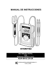
14.3. Remote Engine Start/Stop Connection and Engine Speed Control
This technical instruction describes the connections for engine control from the body - engine start, stop,
and speed control. Start-up is controlled using the START and STOP switches; engine speed is controlled
using the PLUS and MINUS switches. The press button switches are situated on the body. The connection
is made using six wires.
Requirements for remote engine control using switches on the body:
1.
2.
3.
4.
The key is turned into position “I” in the ignition box;
The CC/PTO switch is ON;
The handbrake is activated;
Operating air pressure in the compressed air tanks of both brake circuits.
The following label must be attached next to the switches on the body:
CAUTION!
THE ENGINE CAN BE STARTED FROM
THE BODY ONLY WITH THE HAND
BRAKE ON AND WITH OPERATING
PRESSURE IN THE BRAKE CIRCUIT.
Wiring diagram (for E4 and E5)
“MINUS” SWITCH
WIRE No.
“PLUS”
WIRE No. 430N
“PLUS”
5
“PLUS”
WIRE No. 445NN
5
87A
30
8
87
4
86
ENGINE ECU
C/B
WIRE No.
5
87A
30
2
8
87
4
86
WIRE No.
START
87A
2
8
87
4
86
30
2
85
6
“MINUS”
STOP
85
6
IGNITION BOX
WIRE No. 302AB
85
6
HAND BRAKE TELLWIRE No. 050B
Bodybuilder´s Guideline AVIA ASHOK LEYLAND MOTORS EURO 4 & 5
GND
WIRE No. 9xx
25
1. Connect the relays and control button switches according to the diagram. Insert the relay base in the
slots on the side of the fuse board, lead the wires under the instrument panel to the connection
points. Install the button switches on the body and connect them to the wires.
2. Connection of the remote control wires to the wiring vehicle wiring system:
a) Next to the ignition box, find wire no. 302AB and connect to it the wire marked “IGNITION BOX WIRE No. 302AB” on the diagram. Connect according to TI – 395.
b) Next to the connector on the front panel (marked CTOACI, a vertical 50-pin connector) find wire
050B leading from outlet 6 and connect to it the wire marked “HAND BRAKE TELL-TALE-WIRE No.
050B” on the diagram. Connect according to TI – 395.
c) Next to the connector on the front panel (marked CTOAC3, a horizontal 50-pin connector) find wire
017N leading from outlet 30. Cut the wire. Connect the wire marked “C/B-WIRE No. 17N” on the
diagram to the end leading from the harness to circuit breaker; connect the wire marked “ENGINE
ECU-WIRE No. 017N” on the diagram to the end leading to the connector. Connect according to TI –
395.
d) Remove the PLUS and MINUS switches for engine speed control from the instrument panel; find
wires 445NN, 429N, and 430N and connect them to the wires marked as “PLUS SWITCH” and
“MINUS SWITCH” on the diagram. Connect according to TI – 395.
e) Connect the wire marked as “GND-WIRE No. 9xx” on the diagram (gray) to any gray wire marked
9xx. On vehicles with an E4 engine, it is advisable to connect the wire to the wire leading to the 12V
socket; on E5 vehicles, connect it to the central screw situated in the middle of the front panel of the
cabin.
3. Check the operation of remote engine control when the installation is completed.
Material used:
AMP 444314-1 base
AMP 160759-4 base contacts 4, 6
AMP 925575-1 base contacts 2, 5, 8
4 8725 2 001 relay
button switch (green)
button switch (red)
button switch (black)
red DUOFLUX 830320
3
6
6
3
1
1
2
8
pcs
pcs
pcs
pcs
pc.
pc.
pcs
pcs
FLRY-A wire, cross-section of 0.75 mm2 (1 mm2), white and grey
as needed
cable ties
as needed
14.5. Maximum Speed and Reverse Lock Remote Control
These functions are mainly requested by the manufacturers of sanitation (waste disposal) vehicles. The
speed is limited to 30km/h the contact under the foot step is engaged. At the same time, the reverse
function of the engine is prevented by using an automatic engine stop. These functions are not available
in the configurator. Should such functions be required, they must be included as a special request in the
Notes in the configurator interface. AALM will supply the vehicle with these functions active and with the
wiring prepared for connection anywhere on the chassis.
Bodybuilder´s Guideline AVIA ASHOK LEYLAND MOTORS EURO 4 & 5
26
15. Warranty Conditions
AVIA ASHOK LEYLAND MOTORS s.r.o. will not provide any warranty for the vehicle if a nonapproved body has been installed on the chassis of the D60/D120 Euro4 or Euro5 truck or if the Body
Installation Guideline has not been observed!
AALM shall not be responsible for any failures of the chassis caused by the body (in particular by its
function, attachment, weight distribution over the axles, quality of manufacture and installation, etc.)
unless the body manufacturer has submitted the vehicle with the body for verification by the chassis
manufacturer and unless the chassis manufacturer has issued an evaluation report.
ATTENTION:
The passing lamps must be readjusted on each completed vehicle, i.e. the chassis with the cabin, to the
basic value: -1% !!!
ATTENTION:
The manufacturer of any body whose tailgate, when folded, covers the rear combined lamps, must attach
the following label to a place visible from the driver’s seat:
“THE DRIVER MUST PLACE A WARNING TRIANGLE BEHIND THE VEHICLE WHEN THE TAILGATE IS
FOLDED IN REDUCED VISIBILITY CONDITIONS“
ATTENTION:
After the installation of the body and its accessories is completed, vehicle must be weighed in order to
obtain the operating weight of the vehicle, and the weight must be entered in the Certificate of
Roadworthiness.
After the installation of the body, the body manufacturer must check and complete the automatic loadsensing valve adjustment label.
If a change in the operating weight of the vehicle has changed, the manufacturer will complete line 2.
If the total weight has changed, line 4 must be completed.
The inspection procedure and the procedure for determining the relevant adjustment values are
described in the workshop manual for the D60/D120 series of vehicles.
16. Permitted Exceptions
Upon the written request, AALM may grant an exception from the permitted parameters provided that
they are compatible with the functional, road, and operational safety requirements. This applies, but is
not limited to:
► permitted axle loads;
► permitted total weight;
► modifications of:
- installed component;
- additional installation of power units;
- dimension changes.
Restricting conditions may be added to these exemptions (e.g. a maximum operating speed limit;
restrictions regarding operation on public roads, etc.). Exemptions awarded by AALM are not of a binding
nature for any competent authorities which are in charge of approvals. AALM has not impact on the
granting of exemptions by the competent bodies.
If any of the relevant measures do not meet the roadworthiness requirements, an approval of the
exemption must first be obtained from the Ministry of Transport of the Czech Republic.
The most common cases of technical exemptions include the following:
• change of tyres;
• increase in the permitted total weight of the trailer;
• increased permitted axle loads;
• increase in the permitted total weight.
Bodybuilder´s Guideline AVIA ASHOK LEYLAND MOTORS EURO 4 & 5
27
17. Annexes
17.1 Basic Dimensions of the Chassis
Wheelbase
K
N
L
E
S
A
2 950
3 400
3 900
4 500
5 100
Wheelbase
K
N
L
E
S
A
2 950
3 400
3 900
4 500
5 100
Wheelbase
K
N
L
E
S
G
A
2 950
3 400
3 900
4 500
5 100
5 600
D75 major chassis dimensions (mm)
B
C
D
R
F
1 415
5 590
2 280
1 415
6 040
2 730
1 849
1 736
1 670
6 795
3 230
2 070
7 795
3 830
2 470
8 795
4 430
D90 major chassis dimensions (mm)
B
C
D
R
F
1 415
5 590
2 280
1 415
6 040
2 730
1 849
1 736
1 670
6 795
3 230
2 070
7 795
3 830
2 470
8 795
4 430
D120 major chassis dimensions (mm)
B
C
D
R
F
1 415
5 590
2 280
1 415
6 040
2 730
1 670
6 795
3 230
1 845
1 740
2 070
7 795
3 830
2 470
8 795
4 430
2 520
9 345
4 930
D - 700
1 580
2 030
2 530
3 130
3 730
E max.
5 780
6 230
6 730
7 330
7 930
D - 700
1 580
2 030
2 530
3 130
3 730
E max.
5 780
6 230
6 730
7 330
7 930
D - 700
1 580
2 030
2 530
3 130
3 730
4 230
E max.
5 780
6 230
6 730
7 330
7 930
8 430
* E - the maximum dimension of the body applies to the regular (day) cabin
Bodybuilder´s Guideline AVIA ASHOK LEYLAND MOTORS EURO 4 & 5
28
17.2 Position of the Lateral Protective Devices
- Basic dimensions – 17.5“ wheels
- Basic dimensions – 19.5“ wheels
Bodybuilder´s Guideline AVIA ASHOK LEYLAND MOTORS EURO 4 & 5
29
17.3. Position of the Rear Underrun Protective Device
Bodybuilder´s Guideline AVIA ASHOK LEYLAND MOTORS EURO 4 & 5
30
Bodybuilder´s Guideline AVIA ASHOK LEYLAND MOTORS EURO 4 & 5
31
Bodybuilder´s Guideline AVIA ASHOK LEYLAND MOTORS EURO 4 & 5
32
Installation of the Ringfeder drawbar in the rear overhang
Bodybuilder´s Guideline AVIA ASHOK LEYLAND MOTORS EURO 4 & 5
33
Bodybuilder´s Guideline AVIA ASHOK LEYLAND MOTORS EURO 4 & 5
34
Bodybuilder´s Guideline AVIA ASHOK LEYLAND MOTORS EURO 4 & 5
35