1
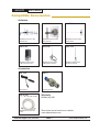
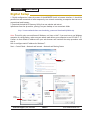
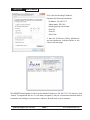
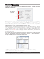
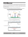
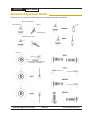
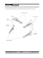
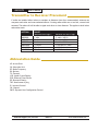
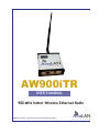
AW900iTR
USER’S MANUAL
900 MHz Indoor Wireless Ethernet Radio
Industrial-grade, long-range wireless Ethernet systems
AvaLAN
W
I
R
E
L
E
S
S
AW900iTR
User’s Manual
Thank you for your purchase of the AW900iTR Indoor Wireless Ethernet Radio.
The AW900iTR includes:
(1) AW900iTR radio in extruded aluminum box
(1) AW2-900 2.5dBi omnidirectional antenna
(1) 110 VAC to 12 VDC power adapter
The AW900iTR-PAIR includes:
(2) AW900iTR preconfigured radios in extruded aluminum box
(2) AW2-900 2.5dBi omnidirectional antenna
(2) 110 VAC to 12 VDC power adapter
TABLE OF CONTENTS
Quick Start Guide . . . . . . . . . . . . . . . . . . . . . . . . . . . . . . . . . . . . 4
Operational Summary Page . . . . . . . . . . . . . . . . . . . . . . . . . . . . . . . . 5
Physical Setup Page . . . . . . . . . . . . . . . . . . . . . . . . . . . . . . . . . . . 5
Digital Setup Page . . . . . . . . . . . . . . . . . . . . . . . . . . . . . . . . . . . . 6
LCD Display . . . . . . . . . . . . . . . . . . . . . . . . . . . . . . . . . . . . . . 11
Technical Specifications . . . . . . . . . . . . . . . . . . . . . . . . . . . . . . . . . 13
Radio Status Information . . . . . . . . . . . . . . . . . . . . . . . . . . . . . . . . 14
Antenna Alignment Guide . . . . . . . . . . . . . . . . . . . . . . . . . . . . . . . . 15
Transmitter to Reciever Placement . . . . . . . . . . . . . . . . . . . . . . . . . . . . 17
Abbreviation Guide . . . . . . . . . . . . . . . . . . . . . . . . . . . . . . . . . . . 17
If you have any questions when configuring your AvaLAN system, the best place to get answers is
to visit www.avalanwireless.com. You will also find the latest updates there. If more assistance
is needed, send email to [email protected].
To speak to a live technician, please call technical support at the number below during normal
business hours.
© by AvaLAN Wireless Systems Inc. All rights reserved.
Revision 03.21.2013
125A Castle Drive
Madison, AL 35758
Sales: (866) 533-6216
Technical Support: (650) 384-0000
Customer Service: (650) 641-3011
Fax: (650) 249-3591
Technical Support (650) 384-0000
PAGE 2
www.avalanwireless.com
AW900iTR
User’s Manual
Compatible Accessories
Antennas
AW11-900
AW10-900
AW15-900
900 MHz Directional 11 dBI
YAGI Antenna
900 MHz Directional 10 dBI
Panel Antenna
900 MHz Directional 15 dBI
YAGI Antenna
AW3X-900
900 MHz Omnidirectional
3 dBI Armored Antenna
AW5M-900
900 MHz Omnidirectional
5 dBI Magnetic Antenna
AW5P-900
900 MHz Omnidirectional
15 dBI Pole Antenna
Accessories
AW-12VA
AW-LA
Auto Adapter
Lightning Arrestor
AW-RFx900
x = 4ft, 10ft, 25ft or 50ft
900 MHz Antenna Extension
Cable
Technical Support (650) 384-0000
Warranty
AW-Warranty-900
These items can be found on our website,
www.avalanwireless.com
PAGE 3
www.avalanwireless.com
AW900iTR
User’s Manual
Quick Start Guide
PROGRAMMING:
Step 1. Gather the AvaLAN radios, power supplies, 2x CAT5 cables and a computer with an RJ45
Ethernet interface.
Step 2. Connect the radios one at a time directly to the PC via an Ethernet cable. Set your computer
to an IP address of 192.168.17.1 (refer to page 6 for detailed instructions). Enter the radio’s default
IP address* of 192.168.17.17 into a web browser.
Step 3. Enter the password and click login. The default password is “password”.
Step 4. Click “advanced admin” at the bottom of the web page.
Step 5. Toggle to select the device type - Access Point or Subscriber Unit. An access point (AP) can
communicate with up to 16 Subscriber Units (SU).
• For the AP, enter the maximum number of SUs communicating with the AP.
• For each SU, set the subscriber ID incrementing from one. (Ex. 1, 2, 3, etc.)
Step 6. Enter the “Network Name” and “Encryption Key” using numbers “0-9” and characters “A-F”.
All radios in a single network must have the same “Network Name” and “Encryption Key”.
TESTING:
We recommend connecting and powering up the units on the bench before deploying in the field.
During bench testing, keep the radios at least 10 feet apart to prevent overload of radio receivers.
Step 1. Power on all the radios with the computer wired directly to the AP.
Step 2. Use the AvaLAN IP finder utility to assign a unique IP address to each radio. (See page x)
Step 3. Open a web browser to view the operation of all the radios. (See page y)
Step 4. Perform PING flood testing to simulate network data and observe overall performance.
INSTALL:
Every installations is different, however radio performance is typically best at shorter distances
using directional antennae with unobstructed paths in low noise environments. It can be challenging
to determine the best approach for a unique installation. The radio’s browser interface has a link
performance statistics and a spectrum analyzer display that is helpful for troubleshooting radio
interference noise levels. (See page 9).
Please call AvaLAN Technical Support for assistance as needed.
Technical Support (650) 384-0000
PAGE 4
www.avalanwireless.com
AW900iTR
User’s Manual
Operational Summary
The AW900iTR Radio allows the user to create a long-range, wireless Ethernet network with up to
16 subscriber units per access point. The configuration may include any combination of AW900iTR,
AW900xTR and AW900xTP radios. (Please note that older AvaLAN 900 MHz radios can exist on the
same LAN but cannot be used to form wireless links with the AW900iTR units because link encryption
protocols have changed.)
Configuring a wireless link with the AW900iTR requires the establishment of six elements:
•Each radio must know whether it is to be an access point (AP) or subscriber unit (SU).
•Each radio must have an IP address that is unique among all others on the same network.
•The AP must know how many SUs are expecting communication with it.
•The AP and any given SU must agree on which radio frequency channel they are using. This can
be manually set or allowed to change automatically.
•The SU must be assigned a unique subscriber ID to specify which time division slot it will use
when communicating with the AP.
•The AP and any given SU must share a common 128-bit encryption key and 32-bit network name.
The access point (AP) automatically scans for the best of the 12 available radio frequency channels,
encrypts Ethernet data received from the network, and transmits it wirelessly to the correct subscriber
unit (SU). The AP is constantly monitoring the radio link and can automatically change the channel
if performance is degraded due to interference. If two AP units are very close to one another, they
may interfere if operating on adjacent frequency channels. Place them at least 10 feet apart and
manually select non-adjacent channels for their operation. Also, the SU should be placed at least 10
feet from the AP to avoid overloading the radio’s receiver.
Any 10/100 BaseT Ethernet client device (ECD) can be connected to an AW900iTR subscriber unit.
Each SU encrypts Ethernet traffic received from the attached ECD and transmits the data wirelessly
to its AP. Each SU can be plugged directly into an ECD without adding drivers or loading software.
Essentially, once the AP/SU pair is configured and running, it behaves like a transparent Ethernet
cable that encrypts and then passes all traffic including VLANs.
Physical Setup
1. Before placing the radio in its final location, it may be best to perform the digital setup procedure
described in the next section.
2. Connect the AW900iTR’s RP-TNC RF connector to a suitable antenna. A 2 dBI omni-directional
dipole antenna (AW2-900) is included and is suitable for testing and general applications. Application
specific antennas are available if greater range and/or directionality is required. Choose one of our
other antenna models that can be found on our website at www.avalanwireless.com.
3. Power is provided to the unit by means of the 120 VAC to 12 VDC 0.5A wall power supply.
Technical Support (650) 384-0000
PAGE 5
www.avalanwireless.com
AW900iTR
User’s Manual
Digital Setup
1. Digital configuration is done by means of the AW900iTR’s built in browser interface. It should be
powered on and connected at least temporarily to a network containing a computer that can run a
conventional web browser.
2. Download the AvaLAN IP Discovery Utility from our website and extract
ipfinder.exe from the zip archive, placing it on your desktop or in a convenient folder.
http://www.avalanwireless.com/marketing_resources/downloads/ipfinder.zip
Note: This utility only runs on Microsoft Windows, not linux or MAC. If you must use a non-Windows
computer for configuration, make sure your subnet mask allows your computer to see 192.168.17.17.
Connect to that default IP address with your web browser and continue the setup procedure with
step 6.
How to configure static IP address for Windows 7.
Start > Control Panel > Network and Internet > Network and Sharing Center
Click local area
connection
Click
Properties
Technical Support (650) 384-0000
Double Click
Internet
Protocol
Version 4
(TCP/IPv4)
PAGE 6
www.avalanwireless.com
AW900iTR
User’s Manual
Click “Use the following IP address”
Populate the following information:
IP address: 192.168.17.17
Subnet mask: 255.0.0.0
Default gateway: leave blank
Click OK
Click OK
Click Close
3. Run the IP Discovery Utility, ipfinder.exe
and you should see a window similar to the
view on the next page.
The AW900iTR should appear in the list at the default IP address of 192.168.17.17. If it does not, click
“Search” to regenerate the list. If it still does not appear, it may be a connection issue and need to
re-examine the cabling or you may have a subnet or firewall issue on your computer.
Technical Support (650) 384-0000
PAGE 7
www.avalanwireless.com
AW900iTR
User’s Manual
4. Double click the list item that refers to the AW900iTR being configured. You should see a second
window that is similar to this:
Your computer’s
current IPV4
Ethernet address
Current IP of
AvaLAN Radio
The information on the left is the current status of the radio, while the boxes on the right allow
you to change it. It is important that the IP address of the AW900iTR is in the same subnet as your
computer. For example, if the subnet mask is 255.255.255.0, the first three number groups of the IP
address must match. Choose the desired parameters and click “Apply.”
5. Make note of the chosen IP address and password, then click “Go to Device Web Page.” This will
cause your default web browser to launch with the device IP address in the browser address bar. Or
you may launch the browser on your own and enter the web page address manually: http://[the IP
address you just set]. Note: You are not assigning a password, you’re matching the password that
the unit has built into it.
6. The browser page that loads first shows the current device information and provides a login in the
upper right. Log in using the password you just specified (or “password” if you kept the default). If
the login succeeds, you will see an admin page similar to this:
The Device Settings section is where the password, channel, DHCP (enable or disable),
network parameters are defined and/or reconfigured.
Technical Support (650) 384-0000
PAGE 8
www.avalanwireless.com
AW900iTR
User’s Manual
7. The admin page has sections similar to the login page showing radio statistics and device
information plus it adds several new sections. The Device Settings section allows setting the network
information and choosing an RF frequency channel. The default is to allow the radio to choose its
own frequency based on minimizing interference. If you set a fixed channel, make sure the AP and
all SUs use the same one.
Scroll down in the Admin browser page to see these three additional sections:
1.A graphical spectrum analyzer display that may help you to manually select a radio channel
If you need more information about the interpretation of this diagram
please refer to our Spectrum Analyzer application guide.
2.A section to be used if an update to the AW900iTR’s firmware is required
3.An advanced links section
Technical Support (650) 384-0000
PAGE 9
www.avalanwireless.com
AW900iTR
User’s Manual
8. On the Advanced Admin page, set the parameters as follows:
•Choose Device Type: Access Point or Subscriber Unit.
•For Subscriber Units, assign unique ID numbers in numeric order from 1 to 16.
•For an Access Point, enter the number of Subscriber Units that will be communicating with it.
•Choose an 8-digit hex (0-9 and A-F) Network Name that will be common among the AP and its
SUs and enter it. The hyphen is required.
•Choose a 32-digit hex encryption key and enter it. Again, the hyphens are required. This key
must match between the AP and the SU so make a note of it as well.
After entering the parameters, click the “Apply” button to save them to the radio.
9. When all of the radios are keyed and operating, connect them to your network and Ethernet devices as desired and cycle the radio’s power to begin normal operation. Now, browser mamagement
of the SUs can be performed over the wireless network. Note: Avoid plugging actively linked radios
into the same switch because this will corrupt the switch’s routing table and may cause network
problems just as if you had plugged a CAT5 cable directly between two ports of a switch (commonly
called a loop back).
Subscriber Screen Shot
Technical Support (650) 384-0000
Access Point Screen Shot
PAGE 10
www.avalanwireless.com
AW900iTR
User’s Manual
LCD Display
During boot up:
After boot up LCD will display:
1. Current Version
Link Quality
Up arrow (Transmit (TX))
Down arrow (Received (RX))
2. Serial Number
Device type: AP or SU
Channel: CH (current channel)
3. IP Address*
NOTE: *When configured for DHCP mode, the display will look like the image above at boot
up. If it fails to recieve an IP address within 20 seconds, it will default back to the IP address
used prior to reboot. The factory default IP address is 192.168.17.17. Once an IP address
is assigned it will be displayed. When configured for static IP mode, the IP address will be
immediately shown in the display.
Technical Support (650) 384-0000
PAGE 11
www.avalanwireless.com
AW900iTR
User’s Manual
900 MHz Channels
Channel
0
1
2
3
4
5
6
7
8
9
10
11
12
Center Frequency
Auto Mode
903.12500 MHz
905.20833 MHz
907.29167 MHz
909.37500 MHz
911.45833 MHz
913.54167 MHz
915.62500 MHz
917.70833 MHz
919.79167 MHz
921.87500 MHz
923.95833 MHz
926.04167 MHz
Limited Warranty
This product is warranted to the original purchaser for normal use for a period of 360 days from the
date of purchase. If a defect covered under this warranty occurs, AvaLAN will repair or replace the
defective part, at its option, at no cost. This warranty does not cover defects resulting from misuse
or modification of the product.
Technical Support (650) 384-0000
PAGE 12
www.avalanwireless.com
AW900iTR
User’s Manual
Technical Specifications
PARAMETER
SPECIFICATIONW
RF transmission rate
1.536 Mbps
Ethernet throughput
935 Kbps
Output power
+21 dBm (4 Watts EIRP when used with 15 dBi antenna)
Receiver Sensitivity
-97 dBm at 10-4 BER
Range
40 miles line-of-sight with 15 dBi antenna
RF channels
12 non-overlapping channels with 2.0833 MHz spacing
Frequency selection
Automatic or manually selectable via web browser interface
RF Connector
RPTNC Female
Ethernet
RJ-45
Power Connector
P5 2.1 mm
Adjacent band rejection
SAW receiver filter attenuates cellular and pager interference
Mounting
DIN rail clip
Power regulation
Built-in switching regulator
Browser management tools
Statistics, Network Settings, Spectrum Analyzer, Firmware Upgrade
Power consumption
Transmit: 1.7 Watts
Voltage
9 to 48 VDC
Transmit current draw
140 mA at 12 VDC
Temperature range
-40º C to +70º C
Size
110 x 110 x 35 mm
Compatibility
Compatible with AW900xTR and AW900xTP radios
Technical Support (650) 384-0000
PAGE 13
Receive: 0.8 Watts
www.avalanwireless.com
AW900iTR
User’s Manual
Radio Status Information
The Login or Admin pages of the radio’s built-in web browser interface provide many useful pieces of
information that let you know how well the wireless link is working:
Top of Web Page
Version
MAC Address
Ethernet
Uptime
Current version of the radio’s Ethernet interface.
Radio’s hardware MAC Address.
Status of Ethernet connection: 10 Mbps or 100 Mbps, full or half duplex, connected or disconnected.
Total time radio has been active since last power cycle or hardware
reset.
Device Information
Device Type
# of Subscriber IDs Issued
Subscriber ID
Current RF Channel
Connected Subscribers
RF Connected
Radio Active
Product Code
Radio Version
Radio Firmware Release
Access Point (master) or Subscriber Unit (client)
For Access Point only, up to 16 permitted.
For Subscriber Unit only, the ID selected for this radio.
The RF Channel in use. See table in this manual for center frequency.
Access Point only, how many SUs are currently connected (16 maximum).
Yes or No
Active or Standby
4 for multi-point radio
Specific radio module in use
Current version of radio module firmware.
Statistics
Radio RSSI
Radio Block Error Rate
Radio Total Packets
Radio Failed Packets
Radio Passed Packets
Radio Broadcast Packets
Radio Unicast Packets
Radio Average TX Size
Radio Average RX Size
Received Signal Strength Indicator. The radios operate best with this
value between -30 and -80 dBm
Should be less than 10% (check RSSI or spectrum scan if greater.)
Higher values indicate degraded data rate, not necessarily lost data.
# of Ethernet packets received since last reset.
# of packets unsuccessfully transmitted.
# of packets successfully transmitted.
Traffic simultaneously addressed to all devices on the network.
Traffic sent to a single destination.
Average bytes per packet transmitted.
Average bytes per packet received.
Technical Support (650) 384-0000
PAGE 14
www.avalanwireless.com
AW900iTR
User’s Manual
Antenna Alignment Guide
Please be sure to consider the following when installing antennae from AvaLAN:
Vertical polarization
Omni-antenna
Figure 1
11 dBi antenna
Horizontal polarization
Figure 2
Do not aim the omni-antennae
directly at each other
Technical Support (650) 384-0000
PAGE 15
www.avalanwireless.com
AW900iTR
User’s Manual
ATTENTION: When multiple 900 MHz antennas are installed in one area and face the same direction,
antennas should be spaced a minimum of 12 feet apart. When multiple antennas are installed in one
area and face different directions, antennas should be spaced a minimum of 5 feet apart.
Horizontal polarization
0-deg. separation
45-deg.
separation
5 ft physical
separation
12 ft physical
separation
Vertical polarization
Technical Support (650) 384-0000
PAGE 16
www.avalanwireless.com
AW900iTR
User’s Manual
Transmitter to Reciever Placement
If radios are installed either indoors or outdoors at distances closer than recommended, antennas can
overpower each other and cause undesired effects. If testing radios within one or two feet, remove both
antennas. The radios will still be able to signal each other at close distances. This applies to both indoor
and outdoor units.
ANTENNA
AW2-900
AW3x-900
AW5-900
AW10-900
AW11-900
AW15-900
RANGE
Maximum line-of-sight *
Maximum non-line-of-sight
1 mile
1 mile
2 miles
15 miles
20 miles
40 miles
5 walls / 450 ft
5 walls / 450 ft
6 walls / 500 ft
1,000 feet w/ trees
1,200 feet w/ trees
1,500 feet w/ trees
Abbreviation Guide
AP: Access Point
SU: Subscriber Unit
RF: Radio Frequency
RX: Recieve
TX: Transmit
LCD: Liquid-Crystal Display
ECD: Ethernet Client Device
RP: Reversed Polarity
TNC: Need name of plug
IP: Internet Protocol
CH: Channel
DHCP: Dynamic Host Configuration Potocol
Technical Support (650) 384-0000
PAGE 17
www.avalanwireless.com