1
Australian Monitor
PROFESSIONAL AUDIO POWER AMPLIFIERS
CONTRACTOR
and
opof
Audio Amplifiers
OPERATION MANUAL
IMPORTANT!
Please read carefully.
This Operation Manual contains important
information regarding safety precautions,
performance, maintenance and operation of your
power amplifier. You should familiarize yourself
with the contents of this manual before operating
your amplilier.
Safety Precautions and Labelling
The rear panel of the unit has a number of markings and
inlemationally recognized symbols related to the hazards
and precautions that should be taken when operating
MAINS connected equipment.
The presence of a LIGHTNING FLASH with an arrowhead contained within the boundaries of a equilateral
triangle is intended to alert the user that dangerous
uninsulated voltages may exist within the units enclosure.
These voltages may be of a sufficient magnitude as to
constitute the risk of an electrical shock.
This symbol is reinforced with the text:
ICAUTION!
RrsK oF ELEcTRTcAL sHocK /lt\
Do Nor oPEN
,/ t \
REFER SERVICING TO
QUALIFIED PERSONNEL ONLY
The user should not attempt to service the unit. Only
qualified and knowledgeable personnel familiar with the
intemal wo.kings of the unit should attempt any repair,
servicing or authorized modification to the unit.
NO USER SERVICEABLE PARTS INSIDE
The unit does not contain any parts which the user can
service or re-use in this or any other product.
The presence of an EXCLAMATION MARK contained
within the boundaries of a equilateral triangle is intended
to alert the user thal there is important operating and
mainlenance literature that accompanies the unit.
lf you are in need of special assistance and the informa-
tion you require is outside the scope of this manual,
please contact your nearest service agent or Australian
Monitor direct:
IWARNING!
THE TECHNICAL OFFICER
AUSTRALIAN I\,4ONITOR Pry LTD,
29 HOPE ST
ERMINGTON. SYDNEY. N.S.W.
DO NOT EXPOSE TO EITHER
RAIN OR MOISTURE
AUSTRALIA.
The unitshould not beoperated in a situation where it may
encounterlhe entry ofwater, rain, or anyfluids. To expose
the unit to the above conditions may make the operation
of the unit hazardous and increase the risk of electrical
shock.
/tu
Local
lntemational
21 15
Phone
9355
9355
(02) 874
(612) 874
Fax
(02) 874 9366
(612) 874 9366
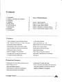
Contents
1. lntroduction
2. Controls, Connectors &
3. lnstallation
4. Operation
5. Bridge Mode
6. Load lmpedance
7.
8.
9.
lndicators
+
List of Illustrations
5
q
12
14
15
16
17
Maintenance
Warranty
Specifications
Figure
1
. Block Diagram
Figure 2. Front Panel Layouts
Figure 3. Rear Panel Layouts
Figure 4. 'Speakon' Connector
4
a
WirinS
Figure 5. Bridge Mode Speaker Wiring
.l
1
14
18
Features:
- Custom designed, heavy duty alloy
chassis.
- Open modular construction, for ease of
servicing.
distribution
- Well-regulated, high current power supply.
- High VA-capable toroidal mains transformer.
- Binding post output connection
- Stereo or bridged / mono operation.
- lnput signal XLR and tag strip connector
- 21 Position detented attenuators.
- Symmetrical weight
-
1
Watt output indication.
- Output clip indication at -'l dB
Massive heafsink and heat-exchangers.
- Efficient front to back cooling.
- Single speed automatic axial fans.
- Output fault indication.
- Plug in signal processors (optional).
- High-quality, close{olerance components
throughout.
Protection Features
- Suppression of inrush cunent at mains
turn-on.
- lnput overvoltage protection.
- lnput muting at
turn-on.
- lndependent DC supply rail fuses.
- Layout, grounding, decoupling and componentry
have been optimized to provide the user with
-Radio-frequencyinterferencesuppression. stability,reliabilityandlongevity.
- Short-circuit protection and indication.
Australian Monitor
ltu
l.Introduction
Congratulations on choosing Australia n Monitorlot your
professional amplification requirements.
A drive stage which in turn drives a fan-cooled, class AB,
MOSFET output stage configured as a source follower.
The unit operates from
a high
current-capable linear
The design ofyouraudio poweramplifierembraces all the
power supply.
aspects of a well designed unit. The visual design, mechanical, electrical and sonic parameters, along with our
The Contractor, Opal and pA Series are 2 units tall (3.5"),
dedicated manufacturing processes, have all been
optimized to provide a professional tool that exhibits
quality, reliability and longevity.
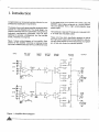
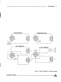
Figure 1 shows a block diagram of the amplifier. Each
channel of the amplifer comprises a balanced active
inputwith a buffered attenuator driving a differentialclass
PRE,AMP
ST AGE
INSERT
POINT
BUFFER
S TAGE
in 19' wide rack mountable cases.
These units have been specifically designed to deliver
their high power output with minimal distortion, and pro_
vide the critical degree ofcontrol required by your speakers, at high duty cycles for exlended periods.
DRIVER
ST AGE
OUTPUT
STAGE
OUTPUT
,I
CHA
o/P
CHB
O/P
Figure 1 Amplifier Block Diagram
/tu
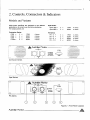
2. Controls, Connectors
& Indicators
Models and Variants
While these amplifiers are designed to suit different
applications, all variants use the same electronics.
The output powers are:
Contrac'tor Series
=
=
=
C1200 =
C300
C600
C800
:
2x
2x
2x
2 x
Opal Series :
Opal 1202 =
Opal 2802 =
'175W
2x
2x
300W
2x
2x
2x
2x
175W 4 ohms
300W 4 ohms
400W 4 ohms
600W 4 ohms
4 ohms
4 ohms
PA Series:
175W
300w
400w
600w
4
4
4
4
ohms
ohms
ohms
ohms
PA-3
PA-6
PA-8
=
=
=
PA-12=
fu,Austanan Monitor
-o,g
c600
ol:lr
\-:-:
Contractor Series
N
OD
Opal Series
Figure
Aushalian Monitor
2
Front Panel Layouts
/tu
6
Controls & Connectors
Front Panel
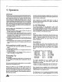
Figure 2 shows layouts of the front panels; the section
numbers refer lo areas on the drawing. The functions of
the controls and indicalors are as follows:
l.
fans will continue to run and once the amplifier has
had a cooFdown period the unit will restart, automatically providing inrush cunent suppression and
input muting.
Faultlndicator
This amber LED will flash when a fault condition
exists.
The fault detection circuit monitors the difference
between drive and output of your amplifier.
A short on the speaker output or a blown negative
rail fuse the LED will flash brightly in sync with the
programme. This LED willalso flash with programme
peaks forgross overloads; or if the load is 2 ohms or
less.
The circuit has two stages of operation:
1. lt will provide indication (e.g gross overload) but
does not affect the input signal_
2. lt will indicate and mute the input signal (e.g
shorted output).
2. Attenuator
Level control for your amplifier is provided by a 21
position detented potentiometer and indicates gain
reduction in decibels from the '0 dB' position (maximum gain, no attenuation).
3. Power Switch
Press the switch to the right for power ON. press
the switch to the left for power OFF. At start-up
(turn-on) the input to the amplifier is muted by 30dB
for approximately two seconds.
4. On/Thermal Indicator
This is a dual colored LED which will normally be
green and indicates that the amplifier is on and
receiving mains power.
ln the advent of a thermal overload this LED will tum
red indicating that the internal operating temperature of the amplifier has exceeded a safe level of
operation and that the amplifier has shut down. The
/tu
5.
Status Indicator
This is a dual colour LED which displays the status
of the output stage and displays three tevels of
operation. These levels are:
Below 1
(unlit)
1 watt and
(green)
1dB below actual ctipping (red)
watt
above
The LED will turn green once the output voltage
exceeds 2.828 volts (1 watt re 8 ohms, or 2 watts re
4 ohms).
The LED will change to red once the output exceeds
the -1dB point before actual clipping of the amplifier's output stage. The threshold of the -1dB point is
with reference to the amplifier supply rails and will
alter with changes in the mains supply, changes in
the load, and duty cycle fluctuations.
The attack and delay time (ballistics) of the status
circuitarethoseof a Peak Programme Meter(p.p.M.)
lf using this indicator to line up sensitivities, apply a
steady tone (e.g slate on a mixing console). The 1
watt level is the point when indicator comes on, re g
ohms, (or 2 wafts for 4 ohm loads).
The amplilier is not damaged by running into clipping, butyourspeakers may be. To maximisethe life
of your speakers, try to keep clipping infrequent.
Controls & Connectors
7
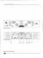
Rear Panel
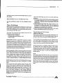
Figure 3 shows layouts of the rear panels; the section
numberc refer to areas on the drawing. The functions of
the controls and indicators are as follows:
6.
9. Mains Lead Connector I.E.C.
Your amplifier is supplied with a IEC mains lead
(power cord) appropriately rated for the mains supply voltage marked on the rear panel of your ampli-
Balanced Input
fier. The wires in the mains lead are coloured
accordance with the following code:
BROWN
= ACTIVE
A female 3 pin XLR connector is provided on each input:
Pin 1=Signal Ground
Pin 2 = Cold (inverting or reverse phase)
Pin 3 = Hot (non-inverting or in phase)
BLUE
(Contractor version only)
mains Iead.
10. Mains Fuses
M 205 fast blow type fuses are used in these amplifiers. Fuses need to be replaced with the same type
and the value must be as follows:
A three terminal barrier strip connector is provided
for'hard wiring'signal input in permanent situations. This input is parallel with the input XLR.
C300/Opal1202lPA3
C600/Opal2802/PAO
c800
c1200tPA8tPA12
7. Signal Ground Lift Switch
8. Binding Post Outputs
Binding posts (banana jacks) are provided for
speaker output termination with banana plugs,
spade type lugs or bare wire. The red post is used
as positive and the black post is used as negative.
Australian Monitor
EARTH
Note: 110V version are supplied with heavy duty
potentiometer is provided on all Contractor models
for input level control on each channel.
connector). The amplifier should be turned off
before engaging this switch! Please read the
Hum Problemsintormation in the Operatlon section
of this manual-
=
Your unit must always be earthed!
A rear panel mounted 21 position detented
(C800 & C1200 only)
When this switch is engaged it disconnects signal
ground from the input connectors on both channels.
It is intended to be used to isolate earth loops (due
to different ground potentials between source equipment and the amplifier), or stray magnetic field pick
up on the input ground/shield wiring. (lt does not
interrupt signal ground continuity on the strapping
NEUTRAL
GREEN&YELLOW
6b Level Control
6c Barrier Strip Input
=
in
I
l.
34
64
7A
10A
Bridge Switch
Pushing this switch in engages the BRIDGED/MONO
mode of operation. ln this mode your amplilier will
only accept signal applied to channel A's input XLRs
and the level of both channels will be controlled by
channel A's attenuator. The output from channel B
will automatically be of the opposite polarity (reversed phase) and speaker termination should be
sourced from the red binding-post outputs. Please
rcad lhe Bridge Mode section of this manual.
CHA +VE Phase
CHB - VE Phase
/tu
8
Controls & Connectors
&
.Outp!t
,ffi
\BS
.d*I
Opal & PA Series
Figure
/tu
3
ol a4lt-l
lUlUl ol l//z=.\\
ourour '-' r.rd.
l\tt " -///l E-F*-r
| ;:-t//
t*c-h
10 m
io lU
Rear Panel Layouts
/tlt--__lt\
/.
\ tlt
| 0 0 ltt.\/
\tL\rill
-ffi
:a
o
lQlQl
I
i
A/l<_\
o
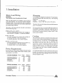
3. Installation
Mains Lead Wiring
Mounting
WARNING
Your amplifier is designed for standard 19'rack mounting, and occupies 2 EIA rack units (3.5"). The mounting
Your amplifier must be earthed at all timesl
centers are:
When you first receive your amplifier it may not have a
mains plug attached. You must ensure that an appropriate plug is used. It must correspond with the amplifier's
current (ampere) requirements, and meet the approval of
your local energy authority.
Vertical:
The wires in the mains lead are coloured in accordance
with the following code:
We recommend that you provide additional support for
the amolifier, especially if road use is planned, as the
GREEN&YELLOW=EARTH
Connect to the terminal marked with the letter E.
with the EARTH SYMBOL, or coloured GREEN.
BLUE = NEUTRAL
Conneci to the terminal marked with the letter N,
(or colored WHITE in USA and Canada,
or coloured BLACK in the United Kingdom).
BROWN = ACTIVE (LIVE)
Connect to the terminal marked with the letterA or L.
(or colored BLACK in USA and Canada,
or coloured RED in the United Kingdom).
Ensure that your mains supply voltage is the same as the
rear panel mains voltage marker. Each model's power
consumption is as follows:
Amps
C300/Opal1202lPA3
C600/Opal2802/PA6
c800/PA8
c1200tPA12
6
15
15
?0
220-240 Volt Models Amps
Watts Watts at
at idle full power
50
100
120
160
2200
Watts
Watts at
at
C300/Opal1202/PA3
C600/Opal2802/PA6
c800/PA8
c1200tPA12
Australian Monitor
3
6
7
10
The slots in the mounting flange will accept boll diameters
up to 1/4" (6.35mm).
amplifier's weight can bend some racks. This support can
be provided by secure shelving, support rails, or rear
panel support brackets.
Cooling
Allamplifiers are cooied by an axialfan which draws cool
airfrom the front of the unit and expels the heated airfrom
the side of the unit. The C800 & C'1200 amplifiers expei
the heated air from lhe rear of the unit. Standard units
offer speed control fans which are turned on when the
output level s above 2 watts into 4 ohms. and stay on
while the heatsink is hot. The C800 & C1200 offer two
speed fans which normally run at half speed, and switch
to full speed when the internai heatsink temperature
exceeds 60oC (128"F).
Power Requirements
110-120 Volt Models
3.0'(76.2mm)
Horizontal: 18.2'to 18.6" (461.2mm to 473.8mm).
idle
An unrestricted airflow into and out from the unit must be
provided. Any restriction of the air flow will cause heat to
build up within the unit and possibly force the unit into its
thermal shutdown mode.
450
1000
1400
full power
50
100
120
160
450
1000
1400
2200
/tu
I
I
10 Installation
Input Wiring
NOTE. lnput signal ground
safety ground (earth).
OutputWiring
is not to bo used as
a
When wiring to your speakers always use the largest
gauge wire your connector will accept. The longer the
speaker lead the greater the losses will be, resulting in
The input to your amplifier is a balanced 3-pin system and
requires allthree pins to be connected. Only high quality
reduced power and less damping at the load. We recommend using a heavy duty two core flex (four core flex if biamping), 10 to 12 gauge (2mm'?to 2.smm'?or 50/0.25 or
equivalent) as a minimum.
twin-core shielded cable should be used.
XLR Inputs
When wiring for a balanced source the connector going
to the inputs of your amplifier should be wired as follows:
Pin 3 = HOT (non inverting)
Pin2=COLD(inverting)
Pin 1=Ground/Shield
When wiring from an unbalanced source you must
ensure that pin 2 is connected to pin 1 (input ground),
either by linking the pins in the input connector or at the
source equipment output wiring. Therefore when wiring
for an unbalanced source:
Pin 3 = Hot (in phase with the amplifier's output)
Pin 2 = Connect to pin 1 (Ground/Shield)
Pin 1 = Ground/Shield
Binding Post Outputs
When terminating to the 4 mm binding post (banana jack)
output connectors, banana plugs or spade type lugs can
be used. The red terminal is positive and the black
terminal is negative.
running in BRIDGE mode, only the red binding posts are
used. Channel A provides the positive output to the load
and channel B provides the negative output to the load.
lf
'Speakon' Outputs
Barrier Strip Inputs
(C800 & C 1200 only)
When using the NEUTRIK 'Speakon' (NL4MP) connector
for speaker output, use only the mating NEUTRIK NL4FC
in-line connector. This connector is designed so that both
channels can be fed from a single connector.
The barrier strip connector on the Contraclor Series
models is wired in parallel with the female XLR input
Two 'Speakon' connectors are provided on the other
connector as follows:
Pin 3 = +ve (non-inverting)
Pin2=-ve(inverting)
Pin 1 = GND (input signal ground)
amplifier. The channel A 'Speakon' actually carries both
channel A & channel B outputs (see figure 4: Speaker
Wiring Diagrams). The channel B 'Speakon' carries only
the channel B output. This gives you options of connecting outputs separately or together through a single or two
connectors-
NoTE. Some in-line XLR connectors have a termination
lug that connects directly to the chassis ofthe connector.
Do not link this lug to pin 1 at the amplifier's inpui as it will
defeat the amplifier's input grounding scheme.
This lug is often referred to as a'drain'and is used to
provide a circuit to the chassis (not signal ground) for
shielding purposes. This is usefulwhen further isolation of
signal grounds is required between source and destination, eg to help in reducing earth loop noise, or noise
induced into signal grounds from stray magnetic fields.
/tu
Installation
SINGLE@NNECTION
11
BRIDGEDCO NECTION
C8 A/LFFT
OR
cH 8/FlrcsT
SPE AK ON
DUAL CONIGCNON
CHA
CH
A/L
SPEAKON
Figure
Australian Monitor
4 Neutik'Speakon'
Connector wiring
/tu
t2
4. Operation
IMPORTANT
All signal source equipment should be adequately earlhed.
This not only ensures your safety but everybody else's as
well. Faults can and do occur in mains connected equip-
ment where the chassis can become 'live' if it is not
properlyearihed. ln lhese ingtances the fault in a 'floating'
(ungrounded) piece of equipmentwill look forthe shortest
path to ground which could possibly be your amplifier's
input. lf the fault cunent is large enough itwill destroy the
input to yourampliferand lookforthe next available paih,
which may be you!
Before making any connections to your amplifier obssrve the following:
1. Ensure the mains voltage supply matches the label on
lhe rear panel of your amplifier.
2. Ensure that all system grounds (earlhs) are connected
to a common point. Avoid powering several pieces of
equipment from multiple power sources that may be
separated by large distances.
3. Check the continuity of all interconnecting leads to your
amplilleq ensure thatthere are no open orshort circuited
conductors.
4. Ensure that the power handling of your load (speakers)
can adequately cope with the power output of the amplifier.
Before operating your amplifier, ensure lhat:
- the attenuators are at the OFF position (fully anticlockwise).
The ICS circuit also operates a 30dB inputmute. After two
seconds this mute willrelease, allowing any applied input
signal to pass unattenuated.
a couple of
seconds before switching the unit on again. This allows
When switching the amplifier OFF wait
the ICS circuit to reset.
Level Matching
'
The normal position for lhe attenuator is the '0 dB'
position (tully clockwise, no attenuation). ln this posilion
the amplifier operates al full gain. Tuming the attenuator
back (anticlockwise) reduces the input sensitivity by the
amount marked on the attenuator scale.
NOTE.
lf full power output is required you should operate your
amplifier with the front panel attenuator above the -15d8
position, otherwise clipping of the input circuitry and
some resultant distortion will occur before full output
power is achieved.
Sensitivity
Your amplifier is a linear device operating with a fixed
inpulto-output voltage gain. The maximum output voltage swing is determined by: the applied mains voltage,
the load, load type, and the duty cycle of the applied
- the power switch is OFF.
- the GROUNO LIFT Switch is not engaged (should be in
signal.
the 'out' position).
- the BRIDGE Switch is not engaged unless you are running the amplifier in bridged mode.
The voltage gain facior of your amplifier is:
(or 25dB)
c300
19.9
Powering Up
REMEMBER
The amplilier should be the last piece of equipment that
you tum ON, and the first piece of equipment that you
turn OFF.
We recommend turning the attenuators on your amplilier
down when fuming the unit on.
When you power up, your amplifier goes through an
establishment period before it will accept signal. The
lnrush Cunent Supression (lCS) circuit is in operation for
the tirsl 0.5 seconds. This limits the mains cunent to
prevent 'nuisance-tripping' of circuit breakers caused by
high starl-up cunents.
/tu
c600
c800
PA3
PA6
PA8
lPA12
'12O2
Opal2802
C12OO
Opal
x
x
x
29.0
37.0
45.25 x
19.9 x
29.0 x
(or 27dB)
(or 31.36d8)
(or33.11d8)
(or 25dB)
(ot 27dB)
The input sensitivity for your amplifier when the
attenuator is at the '0 dB' attenuation position (fully
clockwise) is nominally:
+4.0d8 (1.23 volts) for raled power into an I ohm load.
+2.6d8 (1.04 volts) for rated power into a 4 ohm load.
Each channel of your amplilier has a balanced input
impedanceof25k Ohms (25,000) and should notpresent
a difficult load for any signal source.
The signal source (i.e. the equipment feeding the amplifier) should have an output impedance of 2k Ohms
Operation l3
(2,000) or lower to avoid unwanted highfrequency loss in
the cabling.
lnput overload occurs at +20.5d8u (8.25 volts).
See the specification section for more detailed informa-
tion.
Hum Problems
Mctstequipment is designed for minimum hum when used
under ideal conditions. When connected to other equipment and to safety earth in an electrically noisy environment problems will often occur.
The three 'E's of hum and hum related noise which can
plague your audio system are:
a) Electrostatic radiation,
b) Electromagnetic radiation, and
c) Earth loops
Electrostatic radiation capacitively couples to system
elements causing an interference voltage that mainly
affects higher impedance paths, such as amplifier inputs.
The source is generally a nearby high voltage such as a
mains lead or a speaker lead. The problem can usuallybe
reduced by moving the offending lead away, or by providing additional electrostatic shielding (i.e. an earthed conductor which forms a banier to the field).
Electromagnetic radiation induces interference cunents
into system elements that mainly effect low impedance
paths. Radio transmitlers or stray magnetic tields from
mains transformers are often the cause of this problem.
It is generally more difiicult to eliminate this kind of
interference, but again, moving the source away or providing a magnetic shield (i.e. a steel shield) should hetp.
Earth loops can arise from the interfacing ofthe various
pieces of equipment and their connections to safety
earth.
This is by far the most common cause of hum, and it
occurs when source equipment and the amplifier are
There are thr'ee things you can do to avoid earth loop
problems:
1 . Ensure your niains power for the audio system is .quiet'
i.e, without'equipment on il such as air-conditioning,
refrigeration or lighting which wilt generate noise in thl
earth circuit.
2. Ensure all equipment within lhe system shares a common ground or safety earth point. This will reduce the
possibility of circulating eartl cunents, by referencing
equipmentto the same ground potential.
3. Ensure that balanced signal leads going to the amplifier are connected to earth at one end only.
Signal Gound-Lifr Switch
(c800 & Ci200 onty)
When proper system hook-up has been carried out, you
may still have some hum or hum related noise. This may
be due to any of the previously mentioned gremlins.
The Contraclor Series amplifiers have a ,signal Ground
Lift'switch which disconnects lhe input ground wiring
from the amplifier. A substantial drop in hum and or hum
related noise may result by use of this switch.
Always ensure thatyour amplifieris offand the attenuators
are down when you engage this switch. This switch
should only be used when the amplifier is operated from
a balanced signal source. Be wary of quasi-balanced
outputs, lhese are often no more than floating unbalanced outputs.
NOTE
lf the input ground lift switch is used, you must ensure
adequate shielding of the input wiring. lf the signal source
equipmentdoes not provide adequate shielding you musl
disconnect your shield from input connector pin 1 and reconnect it to the 'drain' conlact going to the amplitier,s
input. This will ensure the shield on your input wiring
actually goes to the amplifierchassis and subsequenflyto
earth-
plugged into ditferent points along the safety earth and
where the safety earth wiring has a cunent in it. The
cunent flowing through the wire produces a voltage drop
due to lhe wire's resistance. This voltage ditference
between the ampllier earth and source equipment earth
appears to the amplifier's input as an input signal and is
amplified as hum.
Ausbalian Monitor
/tu
14
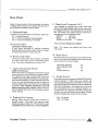
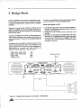
5. Bridge Mode
fierchannels are used
As shown in the diagram there are three steps in setting
up your amplifier for running in BRIDGE mode.
channels.
Whilst the amplitier is OFF:
The term BRIDGE is used when two independent amplito drive lhe same load. The load is
in series (a bridge) between ouhuts of the two amPlifier
1. Connect the signal source lo the channel A female input XLR. The channel A attenuator becomes the level
control for both channels.
2. Engage the 'push to bridge' switch on the rear of the
amplifier.
3. Connect your load between the red binding Posl output
terminals, i.e. the positive side of the load is connected
to the channel A output and the negative side ol the
load goes to the channel B output. There are no further
connections required.
Channel A is used as lhe'dominant' channel and its
outsut is in phase with the input signal; channel B is
phase reversed so its output is exactly'180'out ofphase
with the input signal.
Using two amplifiers his way with a phase difference of
180'provides a doubling ofthe voltage and foultimes the
powerinto the load. The ouputis nowan active balanced
outputA common use of an amplifierin bridge mode is for driving
70 and 100 volt distribution lines or the amplilier can be
used in bridge mode to provide lhe conect voltage/power
requirements for a sPecific load. Each amplifier can
deliver the listed voltage into a load of
ohms.
35V
c300 / PA3 / OPAL 1202
c600 / PA6 / OPAL 2802
c800 / PA8
c1200 I PA12
c=:=-)
(-_-----''-
I
70v
80v
100v
-
-F:+-
A.t?/.\ldHHtrh
FROM SIGNAL SOUBCE
e
\2lql44F#F,',,HN
c-:--)
c_::_=C
::)
Figure
/tu
5
Bridge Mode Speaker Connection (All Models)
A
@r
I5
6. Load Impedance
NOTE
Ensure adequate ventilation and monitor the FAULT
indicators to guard against thermal shutdown when driving two ohm loads.
Your amplifier is designed to be able to deliver more than
twice the curent than that shown on the specification
sheet to cope with difficult loads and/or high energy
waveforms.
The load that a loudspeaker presents to an amplifier is
very complex and at different frequencies can be inductive, capacitive, resistive or a combination of these. With
the complex interaction of these attributes, which alter
from loudspeaker to loudspeaker, a definilive load for an
amplifier does not really exjst.
Loudspeakers operatingwithin an enclosure carrya nominal impedance. This nominal impedance is a rough guide
only to the actual characteristics of the speaker.
As an example, a loudspeakerwith a nominal impedance
of say I ohms, may have an impedance of over 50 ohms
This extra current reserve is the result of over-engineering and is the headroom the amptifier utilizes to controlthe
loudspeaker and deal with the'reactive energy'from the
loudspeaker load that is dissipated within the ampliller.
Your amplifier is able to drive 2 ohm loads or operate in
BRIDGE mode jnto 4 ohms. The operator must be aware
that when driving 2 ohm loads or bridged 4 ohm loads that
the currents running in the output stage are very large and
will cause greater heat build up within the amplifier than
higher impedance loads will.
front panel fault indicators can be used to provide
at resonance, drop to less than 6 ohms after the reso-
The
nance peak and then increase to over 16 ohms for higher
an indication of the 'difficulty' of the load and will give the
operator an indication of the heat build up in the output
stage.
frequencies.
A 6 ohm load makes an amplifier work 'harder' than an 8
ohm load at the same voltage, as it requires more current.
Though various loudspeakers may have an equal nominal impedance, some loads are more'equal'than others
(with apologies to G.B. Shaw).
lf the Fault LED indicators flash with the Status 'clip' LED,
or do nol illuminate until well into clipping then the load
can be considered as normal or easy.
lf the Fault LED indicalor starts to flash before the Status
'clip'LED then the load should be considered complex
As well as this burden on the amplifier, the transient
waveforms found in actual use can demand more current
than the 'steady-state' sinewaves used in most amplifier
bench tests.
The power output of your amplifier quoted on the specifi-
cation sheet is derived from voltage excursion into a
resistive load for a sine wave at a given frequency.
and/or diificult.
For the more complex and/or difficult loads, the illumina-
tion of the Fault LED on programme peaks should be
interpreted as the output level limit. Driving the output
continuously past this point could result in muting of the
output stage, fuse blowing or premature thermal shutdown.
Though this method is in line with the various standards
that exist, it only gives an indication of maximum voltage
swing (before clipping) for a given load. This method of
rating power does not give an indication of the current
(Ampere) capability of the amplifier, nor does it show the
amplifier's ability to sustain high energy waveforms.
Australi,an Monitor
/tu
t6
7. Maintenance
Your amplifler will need minimal maintenance. No internal adjustments need to be made to the unit to maintain
optimum performance.
To provide years of unhindered operation we suggest a
maintenance inspection be carried out every 12 months
or so.
Fuses
WARNING
Make sure the unit is OFF and give the main filter
capacitors time to discharge before removing fuses'
The positive and negative rail fuse holders use spring
loading to apply force to the contact faces of the 3AG fuse
carlridge. The surface around the mechanical contact
area of the fuse can be subject to oxidization in some
environments. Removing and re-installing the fuse will
help renew the contact surface.
You should replace the fuse if the element is sagging or
discoloured.
When checking for a failed fuse, do not rely on visual
inspection alone. You should use an ohmmeter to check
continuity.
Fans
Due to the openness ofthe air path through your amplifier,
very little dust should settle within the amplifier. The unit
has been designed so that any dust and/or foreign particles that do settle within the amplifier will not unduly
hinder the cooling of the unit.
Over time, dust may build up on the leading edge of the
fan blades and reduce their cooling efflciency. The time
taken for this to happen will depend on the environment
and the amount of use.
/tu
'1
l
,'7
8. Wananty
Australian Monitor Pty Ltd, oi 29 Hope St, Ermington,
Sydney, N.S.W. 21 15 Australia, wanants the original
purchaser of each amplifier (purchased from an authorised Australian Monitor dealer) that it will be free from
defecls in material and workmanship for the whole warranty period from the original date of purchase.
Australian Monitorwill, at its option, repair or replace any
unil or component covered by this wananty which be_
comes defective or malfunctions under normal use and
service during the period ofthis warranty, at no charge for
parts or labour to the original owner.
This warranty does not cover blown fuses, faulty fuse
conlacts, thermal problems due to obstructed airflow,
or defects or malfunctions resulting from accidents,
misuse, abuse, operation with the incorrect AC voltage, connection to faulty equipment, modification or
alteration without prior factory approval or service by
unauthorised personnel.
It is the owner's responsibility to ensure that normal
maintenance inspections are canied out at regular intervals as recommended in the maintenance section of this
manual. Australian l/onitor reserves the right to refuse
warranty service where the ownerfails to take reasonable
care in use and maintenance of the amplifier.
To validate this wananty, the original purchaser must
complete and mail the wananty registration card to Australian Monitor at the above address within fourteen days
of purchase.
To obtain warranty service, the equipment should be
shipped to an aulhorised Australian Monitor dealer or to
Australian Monitor at the above address, at the owner,s
expense.
Units with a defaced serial number will not be accepted
for waffanty service. Any evidence of alteration, erasure
orforgery of purchase receipt will also void this warranty.
Australian Monitoraccepts no liabiliV for any consequential damages, whether direct or indirect, arising from the
use or misuse of its products.
Australian Monitor reserves the right to alter its designs
and specifications at any time without notice or obligation
to previous purchasers.
fu nsvanmMonibr
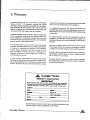
WARRANTY REGISTRATION
IMPORTANT
plaat. compl.L lhl. c.rd and .dum lt lmrn.dh.ly
alLr unpsthg
lh. ,[odocl. Tht. c.rd t. to ba a.nt D|RECTLY to /lu.tr.ll.n Xolttto..
O?El Wa.r.ntt ta .lLcfiv. O'ILY upon r.c.lpt ol thta c..al.
COPAIIV
aDn=13
aEnnl. xc
o rE Rncrla!@
aTA?E
_
cttoE
_
oor
TnY
Ensure that you fill out and send your wananty registration card.
Use this copy to record a duplicate of the detaits.
Australiian Monitor
/tu
l8
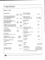
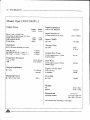
9. Specifications
Model: C800
Input Impedance
Output Power
F.T.C.20 Hz - 2Q kHz @ 0.1%
-lHD
(pre-stress 4dB below rated Power
for t hr & rated power for 5 min)
both channels driven
E.l.A. 1 kHz, <0.05% THD
(pre-stress at rated power for 5 min)
single channel driven
both channels driven
Power
I ohm
260w
2 Ohm Capability
single channel driven
both channels driven
400w
300w
280W
480w
430W
ohms
ohms
1.2V (+3.8dBu)
1 0v (+2 3dBu)
>80 dB
@1kHz
Voltage Gain
31 dB
(= 37 x)
@1kHz
630W
600W
860W
1020W
Output Rise Time
20 kHz square wave
127VPP
2.4 t\S
127YPP
42VlPtS
(leading edge)
510W
SIew Rate
500w
20 kHz square wave
(leading edge)
Distortion
@ 0.5 dB below cliPping re 4 ohms
THD @ 1 kHz
IMD SMPTE (60 Hz / 7 kHz 4:'1)
IMD CCIF (14 kHzl 15 kHz 1:1)
At rated output into 8
At rated output into 4
Input CMRR
driven
driven
Bridge mode
25 kohm
Line to Line. Balanced
4 ohm
Input Sensitivity
Pulsed @ 1 kHz. at onset ol clipping
10% duty cycle, single channel
10% duty cycle, both channels
Power
Signal / Noise ratio
<0.005%
<0.015%
<0.008%
linear (30 kHz)
A weighted
100 dB
104 dB
Crosstalk
Frequency Response
-0.5/ -0.15 dB:
-3dB:
@1kHz
< -90 dB
20Hz-20kHz
5Hz-95kHz
Weight
Output Impedance
15 milliohm
@1kHz
(typical)
Damping Factor
@ 1 kHz,
/tu
I
ohm load
500
net
packed
Dimensions
37.51b / 17 kg
42.161b l20kg
HxWxD
3.5 x 19 x 14.8 inch
excluding handles
88 x 482 x 375 mm
3.5 x 19 x 17.9 inch
including handles
88 x 482 x 455 mm
high)
units
2
(19 inch EIA rack mounting,
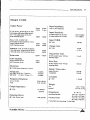
Specifications
19
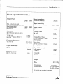
Model: C1200
Output Power
F.T.C. 20 Hz - 20 kHz @ 0.1% THD
(pre-stress 4dB below rated power
for t hr & rated power for S min)
both channels driven
E.l.A. 1 kHz. <0.0570 THD
(pre-shess at rated power for S min)
single channel driven
both channels driven
Pulsed @
Input Impedance
Power
Power
8
4 ohm
ohm
At rated output into 8 ohms
At rated output into 4 ohms
@'l kHz
430W
700w
400w
605W
.23V (+4dBu)
930W
900w
1200w
1400w
>80 dB
Voltage Gain
@ 'r kHz
10% duty cycle, both channels driven
33 dB
(= 45 x)
Output Rise Time
20 kHz square wave 145vpp
2.4 pS
(leading edge)
800w
700w
Distortion
@ 0.5 dB below clipping re 4 ohms
THD @ I kHz
IMD SMPTE (60 Hz / 7 kHz 4:1)
IMD CCIF (14 kHz I '15 kHz 1:1)
1
'1.1V (+3dBu)
Input CMRR
1070 duty cycle, single channel driven
2 Ohm Capability
single channel driven
both channels driven
25 kohm
Input Sensitivity
1 kHz, at onset of clipping
Bridge mode
Line to Line. Ealanced
Slew Rate
20 kHz square wave 145vpp
(leading edge)
50V/pS
Signal / Noise ratio
<0.005%
<0.015%
<0.008%
linear (30 kHz)
A weighted
100 dB
105 dB
Crosstalk
Frequency Response
-0.5/ -0.15 dB:
-3dB:
@ 1 kHz
20Hz-29kHz
5Hz-95kHz
Output Impedance
@1kHz
packed
15 milliohm
Dimensions
excluding handles
Damping Factor
Ausbda Monitor
Weight
net
(typical)
@ 1 kHz,8 ohm load
< -90 dB
500 (typical)
42 lb/19k9
47.5 tb I 2,t kg
HxWxD
3.5 x 19 x'14.8
88 x 482 x 375
including handles
3.5 x '19 x 17.9
88 x 482 x 455
(19 inch EIA rack mounting, 2 units high)
inch
mm
inch
mm
/tu
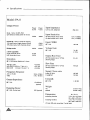
20 Specifications
Model: PA-8
Output Power
E.l.A. 1 kHz, <0.05% THD
(pre-stress at rated power for 5 min)
Power
Power
Input Impedance
8
4 ohm
Line to Line, balanced
480w
At rated output into 8
At rated output into 4
ohm
300w
Pulsed @ 1 kHz, at onset of clipping
10% duty cycle, single channel driven
10% duty cycle, both channels driven
2 Ohm capability
single channel driven
both channels driven
Input Sensitivity
630W
600W
860W
Bridge mode
25k ohm
1020W
ohms
ohms
Input CMRR
@lkHz
1.2V (+3.8dBu)
1.OV (+2.3dBu)
>80 dB
Voltage Gain
@lkHz
31 dB
(= 37x)
510W
500w
Output Rise Time
20 kHz square wave
(leading edge)
Distortion
127vpp
2.4 pS
1?7vpp
4zvllts
@ 0.5 dB below clipping re 4 ohms
THD @ 1 kHz
IMD SMPTE (60 Hz I 7 k{z
IMD CCIF (14 kHz I 15 kHz
4:11
't:1)
<0.005%
<0.01 5%
<0.008%
20Hz-20kHz
5Hz-95kHz
linear (30 kHz)
A weighted
100 dB
104 dB
Crosstalk
Output Impedance
@1kHz
20 kHz square wave
(leading edge)
Signal / Noise ratio
Frequency Response
-0.5/ -0.15 dB:
-3dB:
Slew Rate
15 milliohm
@1kHz
< -90 dB
(typical)
Weight
Damping Factor
@ 1 kHz, 8 ohm load
500 (typical)
net
packed
Dimensions
37
.slb 117 ks
42.61h I
20kg
HxWxD
3.5 x 19 x '14.8 inch
88 x 482 x 375 mm
including handles
3.5 x 19 x 17.9 inch
88 x 482 x 455 mm
('19 inch EIA rack mounting, 2 units high)
excluding handles
/tu
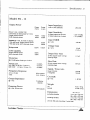
Specifications 2l
Model: PA - 12
Output Power
Power
8
E.l.A. '1 kHz, <0.05% THO
(pre-slrcss at rated power for 5 min)
single channel driven
both channels driven
ohm
Input Impedance
Power
4 ohm
430W
700w
400w
605W
10% duty cycle. single channet driven
10olo duty cycle, both channets driven
2 Ohm capability
single channel driven
both channels driven
930W
900w
1200w
1400w
800w
700w
At rated output into 8 ohms
At rated output into 4 ohms
Input CMRR
@lkHz
Voltage Gain
@lkHz
@ 0.5 dB below clipping re 4 ohms
.23V (+4dBu)
1.1V (+3dBu)
1
>80 dB
33 dB
(= 45 x)
Output Rise Time
20 kHz square wave 14SVpp
(leading edge)
Distortion
THD @ 1 kHz
IMD SMPTE (60 Hz I Z kHz 4:j)
IMD CCIF ('l4kHzt1S kHz j:1)
25k ohm
Input Sensitivity
Pulsed @ 1 kHz, at onset of clipping
Bridge mode
Line to Line, balanced
2.4 sS
Slew Rate
<0.005%
<0.015o/a
20 kHz square wave 145vpp
(leading edge)
50V/pS
<0.008%
Signal / Noise ratio
Frequency Response
-0.5/ -0.15 dB:
-3dB:
linear (30 kHz)
20Hz-20kHz
A weighted
100 dB
105 dB
5Hz-95kHz
Crosstalk
Output Impedance
@1kHz
@ 1 kHz
< -90 dB
15 milliohm
(typical)
Weight
Damping Factor
@ 1 kHz,
I
ohm toad
net
500 (typical)
packed
Dimensions
42 lb
47
i
19 k9
.slb I 21kg
HxWxD
excluding handles
3.5 x 19 x 14.8 inch
88 x 482 x 375 mm
including handles
3.5 x 19 x 17.9 inch
88 x 482 x 455 mm
(19 inch EIA rack mounting, 2 units high)
Australian Monitor
/tu
22 Specifications
Model: Opal 1202/C300/PA-3
Output Power
Input Impedance
Power Power
I ohm 4 ohm
E.l.A. '1 kHz, <0.05% THD
(pre-stress at rated power for 5 min)
single channel driven
both channels driven
Bridge Mode
Line to Line, Balanced
Input Sensitivity
At rated output into 8 ohms
120W
'120W
175W
160W
340W
Voltage Gain
@1kHz
<0.005%
<0.005%
<0.008%
Frequency Response
20
Hz-20kHz
5 Hz- 95kHz
Output Impedance
@1kHz
Damping Factor
kHz,I ohm
load
28dB
(= 19 x)
Output Rise Time
20 kHz square wave
(leading edge)
13Vpp
2.4 pS
20 kHz square wave 145vpp
(leading edge)
35V/pS
1
Slew Rate
Signal / Noise ratio
15 milliohm
(typical)
@1
.23V (+4dBu)
>81.5d8
@1kHz
@ 0.5 dB below clipping re 4 ohms
-0.5/ -0.15d8
-3dB
1
Input CMRR
Distortion
THD @ 1 kHz
IMD SMPTE (60 Hz / 7 kHz 4:1)
IMD CCIF (14kH'zl15 kHz 1:1)
25 kohm
linear (30 kHz)
A weighted
102 dB
104d8
Crosstalk
250'.1
<-90d8
@1kHz
Weight
33 lb / '15k9
37 lbllTkg
net
packed
Dimensions
excluding handles
HxWxD
3.5 x 19 x 14.8 inch
88 x 482 x 375 mm
(19 inch EIA rack mounting,2 units hiqh)
/tu
Specifications 23
Model : Opal 2802/ C600/pA-6
Output Power
E.l.A.
Input Impedance
Power
Power
8
4 ohm
ohm
Line to Line. Balanced
Input Sensitivity
I ohms
1 kHz, <0.05% THD
At rated output into
(pre-stress at rated power for 5 min)
single channel driven
both channels driven
215W
300w
200w
280W
Bridge Mode
560W
@1kHz
Voltage Gain
@ 0.5 dB below ctipping re 4 ohms
@1kHz
<0.005%
<0.015%
<0.008%
-0.5i -0.15 dB
20
-3dB
5Hz-95kHz
Hz-20kHz
>81.5d8
31dB
(=37x)
Output Rise Time
20 kHz square wave
1
13vpp
2.4 pS
Slew Rate
20 kHz square wave 145vpp
35V/pS
(leading edge)
Output Impedance
15 milliohm
(typical)
Signal / Noise ratio
linear (30 kHz)
A weighted
100 dB
104d8
Damping Factor
@ 1 kHz, 8 ohm load
.23V (+4dBu)
(leading edge)
Frequency Response
@1kqz
1
Input CMRR
Distortion
THD @ 1 kHz
li/D SMPTE (60 Hz I 7 k1z 4:1)
IMD CCIF (14 k9z I 15 kHz j:1)
25 kohm
250:1
Crosstaik
@1kHz
-90d8
Weight
net
packed
Dimensions
excluding handles
33 lb / 'tskg
37 lbllTkg
HxWxD
3.5 x 19 x 14-8 inch
88 x 482 x 375 mm
(19 inch EIA rack mounting, 2 units high)
Australian Monitor
/tu