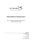
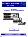
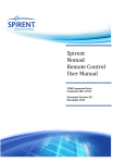
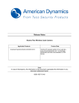
1
Integrated security for an IP-connected world® Hardware Installation Guide June 2012 S2 Security Corporation One Speen Street Suite 300 Framingham, MA 01701 www.s2sys.com S2 Support: 508 663-2505 Document #VR-HW-02 © S2 Security® Corporation 2004-2012. All rights reserved. This guide is protected by copyright and all rights are reserved by S2 Security Corporation. It may not, in whole or in part, except insofar as herein directed, be copied, photocopied, reproduced, translated or reduced to any electronic medium or machine-readable form without prior written consent of S2 Security Corporation. Third party trademarks, trade names, product names, and logos may be the trademarks or registered trademarks of their respective owners. The following are trademarks or registered trademarks of S2 Security Corporation: S2 NetBox®, S2 NetBox® Plus, S2 NetBox® Extreme, S2 NetBox® MicroNode, S2 NetBox®VR S2 Enterprise® Select, S2 Enterprise® Ultra, S2 Enterprise® Ultra 2 S2 Pronto®, S2 Pronto® 2, S2 Pronto®VR, S2 NetVR®, S2 Global™ S2 CumulusSM is a service mark of S2 Security Corporation. Integrated security for an IP-connected world® is a registered trademark of S2 Security Corporation. Contents Introduction ........................................................................................................................................... 1 Where to Go for More Information .................................................................................................. 1 Installation Notes .............................................................................................................................. 2 When Regional Laws Apply ............................................................................................................ 2 Preparing to Install ............................................................................................................................... 3 System Overview ............................................................................................................................. 3 Topology Considerations.................................................................................................................. 3 System Requirements ....................................................................................................................... 7 Mounting the Cabinet ........................................................................................................................... 8 Placing the Cabinet on a Desktop ..................................................................................................... 8 Mounting the Rack Mount Cabinet .................................................................................................. 8 Connecting Power and the Network.................................................................................................. 10 Connecting the Cabinet .................................................................................................................. 10 Back Panel ...................................................................................................................................... 10 Front Panel ..................................................................................................................................... 11 Setting Up a Small Configuration Network ...................................................................................... 12 Interpreting LED States and System Beeps ..................................................................................... 14 Interpreting System LED States ..................................................................................................... 14 Interpreting System Beeps .............................................................................................................. 14 Resetting the NetBox VR / Pronto VR / NetVR IP Address and Login Settings ........................... 15 Using Revert Button to Reset IP Address and Login Settings ....................................................... 16 S2 Security Corporation ii June 2012 Introduction S2 NetBox VR or Pronto VR integrates NetVR video management capability including recording, advanced surveillance, and forensics, into S2 Pronto 2 or NetBoxP2 systems. This guide describes the NetBox VR or Pronto VR hardware installation, including the following information: A system overview (page 3), topology considerations (page 3), and system requirements (page 7). Instructions for mounting the cabinet (page 8). Instructions for connecting power and the network (page 10). Instructions for setting up a small network, which can be used to complete the initial software setup before connecting the controller to the corporate network (page 12). Information on interpreting the various system indicators (LED states and beeps) (page 14). Instructions for resetting the controller IP address and login to factory defaults (page 15). Note: Check the S2 Security web site (www.s2sys.com) for updated specifications, lists of supported devices, and software updates. Where to Go for More Information When the hardware installation is complete, refer to the following publications: The “NetVR Setup and Configuration Guide” for information on configuring the NetVR appliance to work with your S2 security and surveillance equipment. The “NetVR User Guide” for information on administering and operating your NetVR appliance. S2 Security Corporation 1 June 2012 Installation Notes Note to Installers Install according to national and local codes (ANSI/NFPA70). Disclaimer The S2 Security Corporation provides this publication “as is,” without warranty of any kind, either expressed or implied. The S2 Security Corporation shall not be liable for errors contained herein or for incidental or consequential damages in connection with the furnishing, performance, or use of this guide. When Regional Laws Apply Mains Disconnect When required, the power cord serves as a mains disconnect. Earth Ground When required, the enclosure is wired direct to protective earth ground. Class B This equipment has been tested and found to comply with the limits for a Class B digital device, pursuant to part 15 of the FCC Rule, when used with a Würth Elektronik snap Ferrite 74271142. S2 Security Corporation 2 June 2012 Preparing to Install System Overview S2 NetBox VR or Pronto VR is provided in a tabletop or rack mount enclosure that includes both an S2 network controller (NetBoxP2 or Pronto 2) and an advanced video surveillance system integrated to work seamlessly with your security system and cameras. NetVR is provided in a tabletop or rack mount enclosure that includes an advanced video surveillance system integrated to work seamlessly with your security system and cameras. S2 Security systems allow connections to be defined to multiple NetVR appliances, as shown in the following table. Controller # Cameras # of Subordinate NetVRs Pronto 32 4 ProntoVR 32 3 (4)* NetBox 32 4 NetBoxVR 32 3 (4)* Extreme 128 8 Enterprise 1024 64 * ProntoVR and NetBoxVR include NetVR software, therefore 3 additional NetVRs may be connected. NetBox VR, Pronto VR, or NetVR comes with a hardware kit including table top and rack-mount hardware and power cord. An S2 security management system is web-based and does not require a computer to operate. A computer is required only for system setup, programming, and monitoring. NetBox VR or Pronto VR contains embedded controller software including an operating system, a web server, application software, and a database. Topology Considerations Issues to consider when selecting a topology for a NetBox VR or Pronto VR or NetVR installation include simplicity, security, bandwidth requirements, and current network topology. The simplest topology, shown in Figure 1, will be the most common case for small systems. All users and network resources share the same LAN. S2 Security Corporation 3 June 2012 Figure 1. The simplest topology for a NetBox VR or Pronto VR installation. Figure 2. The simplest topology for a NetVR installation. S2 Security Corporation 4 June 2012 Figure 3. A more secure topology for NetBox VR or Pronto VR that includes a router. Figure 4. A more secure topology for NetVR that includes a router. In this case, a router is used to create a subnet for the security system. As a result, the corporate LAN does not directly carry traffic between the NetBox VR or Pronto VR or NetVR appliance and the cameras. The advantages to this topology are increased network security and decreased bandwidth impact on the corporate network. S2 Security Corporation 5 June 2012 S2 Security Corporation 6 June 2012 System Requirements Network Requirements The application is designed to work with Ethernet networks using TCP/IP. Before beginning the installation, obtain the information in the following checklist from the customer’s network administrator. Network Information Checklist: Static IP address for the controller. Subnet mask for the controller. Gateway IP address, if needed. PC Requirements NetBox VR, Pronto VR, or NetVR is designed to work with client machines with these minimum specifications: Windows XP, 7 Dual Core i5 8GB RAM 500GB Hard Drive Screen Resolution of 1600 x 1200 Browser Requirements The application is designed to work with the following web browsers: Internet Explorer Version 8.0 or 9.0 Power Requirements The NetBox VR, Pronto VR, or NetVR appliance: AC input: 100-240 VAC, 4-2A, 50-60 Hz Power must come from a dedicated circuit breaker-protected circuit with an isolated earth ground. S2 Security Corporation 7 June 2012 Mounting the Cabinet The NetBox VR, Pronto VR, or NetVR cabinet can be mounted in a rack or placed on a desktop. Placing the Cabinet on a Desktop There are four rubber feet supplied for placing the cabinet on a table top. Figure 5. The surface-mount cabinet. Use the supplied alcohol wipe to clean the surface before attaching the adhesivebacked rubber feet, as shown in Figure 5. Use the markings on the bottom of the enclosure for placement. Mounting the Rack Mount Cabinet Remove 3 plastic plugs on each side, then use the 6 supplied screws to attach the rack mount brackets to the cabinet. Figure 6. Attaching the rack mount brackets. Bolt the 2U rack mount cabinet, shown in Figure 7, into a standard 19-inch rack. S2 Security Corporation 8 June 2012 Figure 7. The 2U rack mount cabinet dimensions. S2 Security Corporation 9 June 2012 Connecting Power and the Network This section describes how to connect the appliance to a power source and the network. Connecting the Cabinet The cabinet has a IEC receptacle exposed on the back and need not be wired. You will only need to connect the appliance to a power source and to the network. A grounded power cord is provided. To connect a power cord and network cable: 1. Connect the grounded power cord to the power receptacle on the back of the cabinet. 2. Connect the network cable to the RJ45 connector on the back of the cabinet. Be sure to place the cable in the correct connector (G), as shown in Figure 8. 3. To configure the NetBox VR, Pronto VR, or NetVR proceed to Setting Up a Small Configuration Network on page 12 for the steps to connect the appliance to a local PC and then to power. Back Panel Figure 8 shows the location of the back panel connectors. Figure 8. NetBox VR/Pronto VR/NetVR back panel. S2 Security Corporation Item Description Status A PS/2 keyboard/mouse Service use only B PS/2 keyboard/mouse Service use only C Serial port Service use only D Parallel port Service use only E VGA port Service use only F USB ports Service use only 10 June 2012 Item Description Status G LAN Supported H Line in Supported I Power button See page 12 and page 16. J Reset button See page 16. K Revert button See page 15. L Audio (Mic / Speaker) Not supported Front Panel Figure 9 shows the location of the front panel lights/indicators. Figure 9. NetBox VR/Pronto VR/NetVR Front Panel. S2 Security Corporation Item Description Status/States A System Status light LED states are described on page 14. B Disk activity light Flashes when disk is accessed. 11 June 2012 Setting Up a Small Configuration Network Before connecting the controller to the corporate network, be sure to review the following information. You may need to set up a small network between the NetVR appliance and a PC that can be used to configure the system before it is connected to the corporate network. NetBox VR or Pronto VR is configured with a factory default IP address of 192.168.0.250. NetVR is configured with a factory default IP address of 192.168.0.249. If this is a valid address on a corporate network that is available for use, you can connect NetBox VR, Pronto VR, or NetVR in its factory default state to the corporate network before configuring it. The Network Administrator will be able to tell you if the default IP address is available on the corporate network. OR If the NetBox VR or Pronto VR default IP address is not available on the network, it will need to be to be changed during the initial software setup to an address provided by the Network Administrator. If the NetVR default IP address is not available on the network, it will need to be to be changed during the initial network setup to an address provided by the Network Administrator. Important: Do not connect NetBox VR, Pronto VR, or NetVR to the corporate network until its IP address has been verified as available or changed to a valid address on that network. To allow the person who will complete the initial setup to change the system’s IP address before connecting it to the network, you should create a small network between the NetVR appliance and the configuration PC. 4. Connect NetBox VR, Pronto VR, or NetVR directly to local PC (not on the corporate network) using an Ethernet cable. 5. Attach the line cord to the appliance, then to power. Press the Power button. The System Status light turns red. Note: If the system was running when last connected to power, it will start up automatically on restoring power. 6. Ensure that the person who will perform the initial setup knows that the IP address of the configuration PC must be changed to a static value of 192.168.0.x (where x is a number other than 249, 250, or 251). S2 Security Corporation 12 June 2012 Note: The default IP address for NetVR is 192.168.0.249; for the S2 controller 192.168.0.250; and for Mercury boards 192.168.0.251. 7. To proceed with the setup of a NetBox VR or Pronto VR, refer to the Initial Software Setup Guide for detailed instructions. To proceed with the setup of a NetVR appliance, refer to the NetVR Setup and Configuration Guide and to the online help topic “Configuring an S2 NetVR Appliance”. Note: S2 Security systems allow connections to be defined to multiple NetVR appliances, as shown in the table in System Overview on page 3. S2 Security Corporation 13 June 2012 Interpreting LED States and System Beeps For testing and troubleshooting purposes, this section describes how to interpret the different states of the system LED and the various system beeps. Interpreting System LED States For the Revert, Reset, and Power buttons on the back panel (see Figure 8), the following table describes the different states of the LED located on the front of the cabinet and shown in Figure 9. LED State Meaning Off System is down Red, blinking System is starting up or shutting down but is not connected to the network Red steady System is up, network connection is down Blue blinking System is starting up or shutting down, network connection is up Blue steady System is up, network connection is up Interpreting System Beeps # of Beeps Meaning Shutting Down: Two beeps Most operating tasks have been completed and the file system is about to be un-mounted. After waiting a few seconds, you can remove power. Powering Up: One beep Startup is complete and you can log into the system. This may take several minutes. Resetting Controller IP Address and Login Factory Defaults (via the hardware) Three beeps The IP address and login factory defaults have been reset via the Revert button (described on page 15.) Resetting System Configuration Factory Defaults (via the software) Three beeps S2 Security Corporation The system configuration factory defaults have been reset via the Initmode page in the UI, and the system is about to reboot. 14 June 2012 Resetting the NetBox VR / Pronto VR / NetVR IP Address and Login Settings If you are unable to log in to the security application because the IP address or login information is unknown, you will need to reset the controller’s IP address and login settings. Because you cannot do this through the user interface, you will need to use the following procedure: Use the Revert button on the back panel of the unit to reset the IP address and login settings, as described on page 16. The revert procedure does the following: Resets all controller network settings to their factory defaults: The IP address is reset to 192.168.0.250 for NetBox VR or Pronto VR, and to192.168.0.249 for NetVR. o The subnet mask is reset to 255.255.255.0. o The gateway, DNS 1, and DNS 2 are each reset to 192.168.0. o Resets the controller web server port to 80. Resets the password for the default administrator account to “admin.” Re-enables the administrator account, if necessary. Reassigns full system administrator rights to the default administrator account. Resets the interface language to English. Note: Once the controller IP address and login settings have been reset, you can change them at any time by selecting Setup : Site Settings : Network Controller in NetBox VR or from the Setup menu page in Pronto VR. Click the Initmode link to change the network settings and the web server port number. Click the Localization link to change the language. Use the Setup : NetVR Appliances page to change settings for NetVR. S2 Security Corporation 15 June 2012 Using Revert Button to Reset IP Address and Login Settings To use the Revert button to reset controller IP address and login settings for NetBox VR or Pronto VR: 1. Press the Revert button (shown in Figure 8) and hold it for a minimum of three seconds. After 15 to 30 seconds, the system will beep three times. This indicates that the controller settings have been reset. 2. To log into the security application, point your browser to the default controller IP address: 192.168.0.250. Note: The Power and Reset buttons shown in Figure 8 can be used in the following ways: When the system is up and running, holding down the Power button for four seconds or longer causes a shutdown of the system, which is equivalent to unplugging it. Holding down the button for fewer than four seconds causes the LED to blink and shuts down the system in an orderly manner. When the system is not running, pressing the Power button starts the system. Pressing the Reset button causes an orderly power reset of the system. S2 Security Corporation 16 June 2012