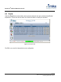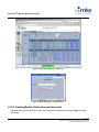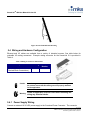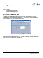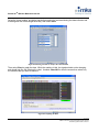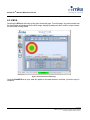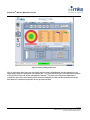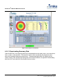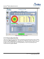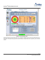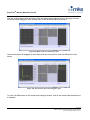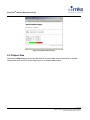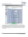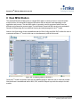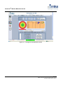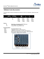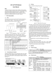
1
SenseLinkTM QM 2.2
Multivariate Fault Detection
User Manual
MKS Instruments, Inc.
Control & Information Technology Products Group
70 Rio Robles Dr.
San Jose, CA 95134
Office: 408-750-2919
Fax: 408-750-2990
SenseLink™ QM Version 2.2
Manual Revision 02
December 2009
SenseLinkTM QM User Manual Version 2.2
Copyright
This manual and the software described in it are copyrighted with all rights
reserved. Under the copyright laws, this manual and software may not be
copied, in whole or part, without the prior written consent of MKS Instruments.
The same proprietary and copyright notices must be affixed to any permitted
copies as were affixed to the original. This exception does not allow copies to
be made for others whether or not sold, but all of the materials purchased may
be sold, given, or loaned to another person. Under the law, copying includes
translating into another language or format.
© MKS Instruments - CIT Products Group, 2009
70 Rio Robles Dr.
San Jose, CA 95134
Preface
About this addendum
This addendum is designed to serve as a guideline to the installation, set up,
operation, and basic maintenance of the Remote Monitoring Unit (RMU) with
the SenseLinkTM QM multivariate monitoring application. The information
contained within this manual, including product specifications, is subject to
change without notice. Please observe all safety precautions and use
appropriate procedures when handling the SenseLinkTM QM hardware product
and its related software.
Technology protected by U.S. patent numbers 7,465,417 and 6,993,404.
2 of 118
© MKS Instruments CIT Products 2008, All rights reserved
Protected by patent number 7,465,417
SenseLinkTM QM User Manual Version 2.2
Table of Contents
1
GENERAL INFORMATION ..................................................................................................................................5
1.1
2
CONVENTIONS USED IN THIS USER MANUAL .......................................................................................................... 5
OVERVIEW...........................................................................................................................................................6
2.1
THEORY OF OPERATION .......................................................................................................................................... 6
2.2
PROCESS VARIABLES .............................................................................................................................................. 7
2.2.1 Digital Inputs...................................................................................................................................................... 7
2.2.2 Analog Inputs .................................................................................................................................................... 8
2.3
PROCESS DOE........................................................................................................................................................ 9
3
QUICK-START INSTALLATION........................................................................................................................10
4
QUICK-START FOR MVA CONTROL...............................................................................................................11
4.1
INTRODUCTION....................................................................................................................................................... 11
4.2
CONNECT ............................................................................................................................................................... 11
4.3
CUSTOMIZING ANALOG INPUTS ............................................................................................................................. 16
4.4
CUSTOMIZING DIGITAL INPUTS .............................................................................................................................. 19
4.5
VIRTUALS ............................................................................................................................................................... 20
4.6
EVENTS .................................................................................................................................................................. 22
4.7
TRIGGERS .............................................................................................................................................................. 23
4.8
COLLECT ................................................................................................................................................................ 25
4.9
RUNNING THE DOE ............................................................................................................................................... 26
4.10 CREATING AND EDITING MODELS ......................................................................................................................... 30
4.10.1
Creating Models Offline using SIMCA P+............................................................................................... 30
4.10.2
Creating Models Online through SenseLink........................................................................................... 32
4.10.3
Editing Models ............................................................................................................................................ 34
4.11 SCALING VIRTUALS ................................................................................................................................................ 35
4.12 RUNNING MODELS ................................................................................................................................................. 37
5
SENSELINK HARDWARE .................................................................................................................................40
5.1
HARDWARE DESCRIPTION ..................................................................................................................................... 40
5.2
MECHANICAL DESCRIPTION .................................................................................................................................. 41
5.3
INSTALLATION ........................................................................................................................................................ 41
5.4
WIRING AND HARDWARE CONFIGURATION ........................................................................................................... 42
5.4.1 Power Supply Wiring...................................................................................................................................... 42
5.4.2 Analog I/O Wiring............................................................................................................................................ 43
5.4.3 Digital I/O Wiring............................................................................................................................................. 44
5.4.4 Combo I/O Wiring ........................................................................................................................................... 46
5.5
DIGITAL INPUTS ..................................................................................................................................................... 47
5.6
DIGITAL INPUT INTERFACE EXAMPLE .................................................................................................................... 48
5.7
DIGITAL OUTPUTS ................................................................................................................................................. 48
5.8
DIGITAL OUTPUT INTERFACE EXAMPLE ................................................................................................................ 49
5.9
ANALOG INPUTS..................................................................................................................................................... 49
5.10 ANALOG OUTPUTS ................................................................................................................................................. 50
5.11 SERIAL PORT CONNECTIONS ................................................................................................................................ 50
5.12 NETWORK CONFIGURATION .................................................................................................................................. 51
5.13 WEIDMULLER THERMOCOUPLE MODULE .............................................................................................................. 51
3 of 118
© MKS Instruments CIT Products 2008, All rights reserved
Protected by patent number 7,465,417
SenseLinkTM QM User Manual Version 2.2
5.13.1
5.13.2
5.13.3
Configuring the Weidmuller Thermocouple ............................................................................................ 51
Wiring and installation................................................................................................................................ 53
Calibrating Thermocouples ....................................................................................................................... 53
SENSELINKTM QM USER INTERFACE ............................................................................................................57
6
6.1
SENSORS OVERVIEW ............................................................................................................................................ 57
6.1.1 Analog Channels ............................................................................................................................................ 58
6.1.2 Digital Channels.............................................................................................................................................. 65
6.1.3 Virtual Channels.............................................................................................................................................. 66
6.2
EVENTS OVERVIEW ............................................................................................................................................... 67
6.2.1 Events............................................................................................................................................................... 68
6.2.2 Triggers ............................................................................................................................................................ 69
6.3
DATA OVERVIEW ................................................................................................................................................... 70
6.3.1 Traces............................................................................................................................................................... 70
6.3.2 MVA .................................................................................................................................................................. 78
6.3.3 PLS ................................................................................................................................................................... 88
6.3.4 MVA Report ..................................................................................................................................................... 89
6.3.5 Export Data...................................................................................................................................................... 90
6.4
CONTROL OVERVIEW ............................................................................................................................................ 92
6.5
SYSTEM OVERVIEW ............................................................................................................................................... 98
6.5.1 Alarms .............................................................................................................................................................. 98
6.5.2 Network ............................................................................................................................................................ 99
6.5.3 Date/Time ...................................................................................................................................................... 101
6.5.4 My Profile ....................................................................................................................................................... 102
6.5.5 Users .............................................................................................................................................................. 102
6.5.6 Audit................................................................................................................................................................ 103
6.5.7 Maintenance .................................................................................................................................................. 105
7
DATA FEATURES (VIRTUALS) ......................................................................................................................107
8
DUAL MVA STATION ......................................................................................................................................112
9
APPENDIX........................................................................................................................................................114
10
MODEL CODE DESCRIPTION ........................................................................................................................115
11
SPECIFICATIONS............................................................................................................................................116
WARRANTY .............................................................................................................................................................118
4 of 118
© MKS Instruments CIT Products 2008, All rights reserved
Protected by patent number 7,465,417
SenseLinkTM QM User Manual Version 2.2
1 General Information
The SenseLinkTM QM is a data collection and monitoring device targeted for the injection molding
industry. The SenseLinkTM QM provides a complete system for injection molding multivariate analysis
and real time quality and fault detection. The SenseLinkTM QM converts electrical and serial data into
an archived, ethernet network available format.
For a complete list of models at the time of this printing, see Appendix.
1.1 Conventions used in this User Manual
Warning
The WARNING sign denotes a hazard to personnel. It calls attention to a
procedure, practice, condition, or the like, which, if not correctly
performed or adhered to, could result in injury to personnel.
Caution
The CAUTION sign higlights information that is important to the safe
operation of the BlueBox, or to the integrity of your files. .
Note
THE NOTE SIGN DENOTES IMPORTANT INFORMATION. IT CALLS
ATTENTION TO A PROCEDURE, PRACTICE, CONDITION, OR THE LIKE,
WHICH IS ESSENTIAL TO HIGHLIGHT.
On screen buttons or menu items appear in bold and cursive.
Example: Click OK to save the settings.
Keyboard keys appear in brackets.
Example: [ENTER] and [CTRL]
Pages with additional information about a specific topic are cross-referenced within the text.
Example: (See page xxx)
5 of 118
© MKS Instruments CIT Products 2008, All rights reserved
Protected by patent number 7,465,417
SenseLinkTM QM User Manual Version 2.2
2 Overview
The SenseLinkTM QM provides a comprehensive system for modeling a process in real-time, providing
predictive results which predict the quality of the part immediately upon being processed. The system
resides in parallel with the process controller, minimizing any impact on the existing process.
Figure 1 Connection to Injection Molding Machine
The SenseLinkTM QM technology detects process deviations in real time and makes an accept or
reject decision based on multivariate statistics. This multivariate analysis provides a contribution chart
with information describing the root cause or interactions that contributed to the rejection of that
suspect part.
2.1 Theory of Operation
The SenseLinkTM QM provides complete data acquisition and modeling functionality, for determining
process results in real-time, all contained in a single unit with no additional software required.
Setup
a) SenseLink is initially used as a general purpose data acquisition system, where the system
connects to the key process signals of the molding machine and calculates the most important
features of each signal.
b) A Design of Experiment (DOE) is run to gather process data and to induce process variation. The
DOE limits should be designed so that all molded parts are acceptable.
6 of 118
© MKS Instruments CIT Products 2008, All rights reserved
Protected by patent number 7,465,417
SenseLinkTM QM User Manual Version 2.2
c) A multivariate model is then created within the SenseLink QM, from the DOE, which captures the
acceptable operating process window of the specific product. As an option, this model can also be
created and edited, outside of the SenseLink QM, using SIMCA P software from Umetrics which offers
data and variable modification capabilities along with extensive data analysis.
d) Each new molded cycle is then compared to the multivariate model, where an accept or reject
decision is made.
e) Validation experiments are then run to refine the alarm limits of the model and to ensure 100%
quality assurance.
Data Acquisition
The system connects to all process variables via analog, digital, serial, or Ethernet based devices. It
collects data at a user defined rate, and publishes data to the modeling engine and archive database.
Multi-Variate Analysis (MVA)
The SenseLinkTM QM creates a model using data from the DOE or from some historical data set that
resulted in 100% acceptable parts. Any new parts are then compared to this known “good” model,
and results such as T2, DModX, and contributions are determined. The results are then returned to
the control engine.
Control Engine
Receives the results from the MVA and determines whether the last process is “passed” or “rejected”.
Logic is then enacted based upon this determination, where the rejected product is automatically
removed from the process via a conveyor belt, robot, etc.
SenseLink QM
An s/w application running on the SenseLinkTM QM hardware provides the functionality for all data
acquisition, control, and user interface (UI). The Linux PC acts as a data storage server and MVA
host creating a complete single unit implementation of MVA control.
2.2 Process Variables
The SenseLinkTM QM connects to existing sensors, from the process, including screw position,
pressure, and temperatures along with digital signals such as mold close, filling, packing, and
plasticating to determine the different states of the molding process. Additional inputs such as mold
cavity sensors, thermolator temps, hot runner temps, dryer temps, etc. can also be added.
2.2.1 Digital Inputs
SenseLink QM requires information about the current process states. The digital signals provide the
system with the ability to calculate important process characteristics during each of the process states.
The digital inputs also define the processing window for data analysis.
7 of 118
© MKS Instruments CIT Products 2008, All rights reserved
Protected by patent number 7,465,417
SenseLinkTM QM User Manual Version 2.2
Table 1 Digital Inputs for Injection Molding Process
ID
DI1
DI2
DI3
DI4
Description
Mold Close
Fill
Hold
Plastication
Unit
24V
24V
24V
24V
Further information
Mold clamped state, mold open signal can alternatively be used
Process state where cavity is filling with injection speed
Process state where cavity is packing/holding with pressure
Process state where screw is rotating/extruding to build up shot
Mold Open
Plastication Time
Pack Time
Fill Time
Mold Open
1 Cycle
Figure 2 Injection Molding Digital Process States
2.2.2 Analog Inputs
The analog inputs provide the system data for analysis. Multiple important process features are
calculated from each analog input.
Table 2 Analog Inputs for Injection Molding Process
ID
AI1
AI2
AI3
AI4
AI5
AI6
AI7
AI8
AI9
AI10
AI11
AI12
AI13
Analog Variables
Nozzle Temp
Barrel Zone 1 Temp
Barrel Zone 2 Temp
Barrel Zone 3 Temp
Injection Pressure
Screw Position
Screw Velocity
Clamp Force
Screw Rotational Speed
Cavity Pressure
Cavity Temp
Barrel Temp Zones
Hot Runner Temps
Units
°C
°C
°C
°C
MPa
mm
mm/s
Tons
RPM
MPa
°C
°C
°C
Description
Temp measure at barrel nozzle
Barrel temp measured in zone 1
Barrel temp measured in zone 2
Barrel temp measured in zone 3
Hydraulic or plastic pressure
Axial displacement of screw
Velocity of axial movement of screw
Tonnage to clamp mold halves
Screw rotational speed during screw recovery
Pressure measured in mold cavity
Temp measured in mold cavity
Any additional barrel temp zones
Any manifold or tip temperatures
8 of 118
© MKS Instruments CIT Products 2008, All rights reserved
Protected by patent number 7,465,417
SenseLinkTM QM User Manual Version 2.2
2.3
Process DOE
The requirements of the DOE are to teach SenseLink the processing window, to induce process
variation, and to develop process data relationships based on the various combinations of process
inputs.
Table 3 Injection Molding Sample DOE
Run
1
2
3
4
5
6
7
8
9
Transfer
Position
-1
1
-1
1
0
-1
1
-1
1
Injection
Velocity
-1
1
1
-1
0
1
-1
-1
1
Pack
Pressure
1
-1
1
-1
0
-1
1
-1
1
Screw
RPM
1
1
-1
-1
0
-1
-1
1
1
Barrel
Temp
-1
-1
-1
-1
0
1
1
1
1
Mold
Temp
-1
-1
1
1
0
-1
-1
1
1
Cooling
Time
1
-1
-1
1
0
1
-1
-1
1
Hold
Time
1
-1
-1
1
0
1
-1
-1
1
The DOE design space should be carefully designed by the customer or by MKS based on the
customers needs. The DOE should be created to emulate long term process variation while still
creating 100% good parts. The average of high and low limits should be the optimum process and at
least one DOE run should be done at that median factor level. The SenseLink creates models based
on the DOE, so the design and time put into the DOE and measuring the parts is of utmost
importance.
9 of 118
© MKS Instruments CIT Products 2008, All rights reserved
Protected by patent number 7,465,417
SenseLinkTM QM User Manual Version 2.2
3 Quick-Start Installation
Stationary Platen
Operator Interface
Moving Platen
Clamping
Cylinder
Mold
Tie Rods
Check valve
Reciprocating
Screw
D1
D1
D2
Pellets
Injection
Cylinder
D4
D4
D2
Polymer
Melt
Barrel
Heaters
D3
D3
Hydraulic
Power Supply
Injection Unit
Process Controller
Clamping Unit
Figure 3 Injection Molding Machine/SenseLink Interconnect
SenseLink hardware resides on the tool and may contain the following connections:
• Power, 24VDC at 1 amp
• Analog inputs (up to 16), specified as either Differential or Single-Ended, 14 bit
• Digital inputs, active low, opto-coupler input
• Digital output, contact closure, normally open, 1A
• Serial RS232/485, 2 channels, for data acquisition from intelligent devices
• Ethernet, 10BT, RJ45 for data acquisition from intelligent devices and link to SenseLink
network
10 of 118
© MKS Instruments CIT Products 2008, All rights reserved
Protected by patent number 7,465,417
SenseLinkTM QM User Manual Version 2.2
4 Quick-Start for MVA Control
4.1
Introduction
Mount and connect the SenseLink to the system.
Once the SenseLink is connected electrically, the following configuration will occur:
Figure 4 SenseLink Setup
4.2
Connect
1. Power up SenseLink by attaching power connector and plugging in 24VDC power supply to
110VAC.
2. Attach Ethernet cable to SenseLink LAN 2 and your PC.
3. Modify your network TCP/IP settings to match the following (PC IP address should have same
base IP address as LAN 2 port which is displayed on unit screen):
PC IP Address:
192.168.1.1
PC Netmask:
255.255.255.0
Figure 5 TC/IP Properties
11 of 118
© MKS Instruments CIT Products 2008, All rights reserved
Protected by patent number 7,465,417
SenseLinkTM QM User Manual Version 2.2
Note
Custom SenseLinkTM QM solutions may have a configuration requiring different
default settings. For custom applications refer to the addendum for specific
default settings
4. Open up your web browser and enter the address of the LAN 2 port 192.168.1.2. You will
then be prompted for a password. Enter “user” for both username and password. You will see
the main SenseLinkTM QM configuration page. There is slight delay as the unit transfers items
to your local browser. A recent update of Java may be required to run the SenseLink applets.
Figure 6 SenseLink Main Page
5. Click on the Traces tab, which will show you the current, running data collection plans.
Collection plan DataCP is by default configured with only virtuals for model creation and Test is
configured with raw data.
12 of 118
© MKS Instruments CIT Products 2008, All rights reserved
Protected by patent number 7,465,417
SenseLinkTM QM User Manual Version 2.2
Figure 7 Traces Main Page
6. Select Chart for collection plan “Test” and a new browser window will open up. Raw data that
has been collected will appear for graphical analysis. There are many data viewing options
available using this graph.
Figure 8 Traces Chart
13 of 118
© MKS Instruments CIT Products 2008, All rights reserved
Protected by patent number 7,465,417
SenseLinkTM QM User Manual Version 2.2
7. Transport the collected raw data to your PC. Under the same Traces tab, in the Download
Data column, select Download. A page will open to provide options on the timeframe of data
you would like to access.
Figure 9 Exporting Collection Plan
8. Click on Download and the data will be sent to your PC for plain text, MS-Excel format, or
graphical viewing.
Figure 10 Downloading Collection Plan
14 of 118
© MKS Instruments CIT Products 2008, All rights reserved
Protected by patent number 7,465,417
SenseLinkTM QM User Manual Version 2.2
Figure 11 Downloaded Raw_Data Collection Plan Example
9. Now you are ready to customize the SenseLinkTM QM for your applications. The following
features can be quickly customized for your application:
•
•
•
•
•
•
•
Scale all values to real units. Also collect min, max, average, derivative, and integral
values.
Change the frequency of data collection
Modify the alarm logic using complex expressions
Email based on alarm events
Graph and analyze data
Change network settings
Define a network share for continuous data export and backup
15 of 118
© MKS Instruments CIT Products 2008, All rights reserved
Protected by patent number 7,465,417
SenseLinkTM QM User Manual Version 2.2
4.3
Customizing Analog Inputs
Select the Analog tab and choose Edit Inputs.
Figure 12 Analog Boards
Edit the input names and scale each signal. Depending on the amount of sensors, multiple analog
boards may need to be used. Once all of the names and scaling are entered, select Save and then
select Activate from the Analog tab.
16 of 118
© MKS Instruments CIT Products 2008, All rights reserved
Protected by patent number 7,465,417
SenseLinkTM QM User Manual Version 2.2
Figure 13 Editing Analog Signals Board 1
Open the I/O Monitor to make sure each point is reading a correct value by selecting the IO Monitor
button.
17 of 118
© MKS Instruments CIT Products 2008, All rights reserved
Protected by patent number 7,465,417
SenseLinkTM QM User Manual Version 2.2
Figure 14 Selecting IO Monitor
Figure 15 IO Monitor
18 of 118
© MKS Instruments CIT Products 2008, All rights reserved
Protected by patent number 7,465,417
SenseLinkTM QM User Manual Version 2.2
4.4
Customizing Digital Inputs
Configure each point as in/out and enter the name of the signals by clicking the Edit button.
Figure 16 Digital Boards.
Select Save when complete.
Figure 17 Editing Digital Signals
19 of 118
© MKS Instruments CIT Products 2008, All rights reserved
Protected by patent number 7,465,417
SenseLinkTM QM User Manual Version 2.2
4.5
Virtuals
Under the Virtuals tab, data features can be calculated using arithmetic expressions and functions
based on the analog and digital process signals. A default set of data features will be provided based
on the users available signals. Any new data features can then be easily added by the user.
Figure 18 Virtual Inputs
20 of 118
© MKS Instruments CIT Products 2008, All rights reserved
Protected by patent number 7,465,417
SenseLinkTM QM User Manual Version 2.2
Figure 19 Click Add New to Create New Virtual Signal.
Figure 20 Adding Virtuals
21 of 118
© MKS Instruments CIT Products 2008, All rights reserved
Protected by patent number 7,465,417
SenseLinkTM QM User Manual Version 2.2
4.6
Events
Under the Events tab, process states such as process start and end can be created using Boolean
expressions. Events can also be used in the virtual calculation to simplify the equations.
Figure 21 Process Events
Click Edit on an event for that particular event configuration.
22 of 118
© MKS Instruments CIT Products 2008, All rights reserved
Protected by patent number 7,465,417
SenseLinkTM QM User Manual Version 2.2
Figure 22 Configuring Events
4.7
Triggers
Create output functions or control sequences that can happen as result of the data analysis. For
example, conveyers or robots can be setup to eliminate suspect parts.
23 of 118
© MKS Instruments CIT Products 2008, All rights reserved
Protected by patent number 7,465,417
SenseLinkTM QM User Manual Version 2.2
Figure 23 Triggers
New trigger can be created easily by user by clicking on Create Trigger button.
Figure 24 Creating New Trigger
Click Edit on any particular trigger to change its configuration/setting.
24 of 118
© MKS Instruments CIT Products 2008, All rights reserved
Protected by patent number 7,465,417
SenseLinkTM QM User Manual Version 2.2
Figure 25 Editing Triggers
4.8
Collect
Under the Data/Traces tab, collection plans can be created which specify the data to collect, the data
sampling rate, and the data publishing rate. By default the DataCP collection plan is setup as the
modeling collection plan with only virtuals selected and the Test collection plan is setup for viewing of
raw analog and digital signals.
Figure 26 Data Collection Plans
25 of 118
© MKS Instruments CIT Products 2008, All rights reserved
Protected by patent number 7,465,417
SenseLinkTM QM User Manual Version 2.2
Figure 27 Editing Collection Plans
4.9
Running the DOE
1. Go to the Vertical Control tab and select the MVA Config page.
2. Ensure that the DataCP collection plan is selected before running the DOE.
3. Also be sure to select the event “Start”, as it is setup as mold open (cycle start and cycle end)
for both Process Start and Process Stop.
4. Select the triggers for Accept and Reject and also for the Health DIO select the System OK,
Model, and Parametric Release digital outputs, which by default are DIO1_1, DIO1_3, and
DIO1_4 by default respectively.
5. Then select Activate to put the changes in place.
26 of 118
© MKS Instruments CIT Products 2008, All rights reserved
Protected by patent number 7,465,417
SenseLinkTM QM User Manual Version 2.2
Figure 28 Setting up Data Collection to Run DOE
6. To begin the DOE select the MVA DoE tab and enter the name of the DOE and the amount of
data collection time needed to run the DOE.
27 of 118
© MKS Instruments CIT Products 2008, All rights reserved
Protected by patent number 7,465,417
SenseLinkTM QM User Manual Version 2.2
Figure 29 Setting up a DOE
7. Select Start. Data is now being collected which will be used to create the model.
28 of 118
© MKS Instruments CIT Products 2008, All rights reserved
Protected by patent number 7,465,417
SenseLinkTM QM User Manual Version 2.2
Figure 30 DOE in Progress
8. Selecting Pause when a process change is needed will pause data collection until the user is
ready to start collecting data again, usually once the process has reach steady state.
29 of 118
© MKS Instruments CIT Products 2008, All rights reserved
Protected by patent number 7,465,417
SenseLinkTM QM User Manual Version 2.2
Figure 31 Pausing Data Collection for DOE Run Changes
9. Then select Continue to start collecting data again. Also, when running a DOE, it is useful to
know how many shots have been run so the number of cycles in the DOE are shown at the
bottom of the page.
10. Select Stop to finish the DOE and store the data.
4.10 Creating and Editing Models
Creating a model can either be done offline through SIMCA P+ and uploaded into the SenseLink
under the MVA DoE page or it can be created online within the SenseLink.
4.10.1 Creating Models Offline using SIMCA P+
Once the data from the DOE is stored in the data section shown above, select Download in the
Export column and save the file.
30 of 118
© MKS Instruments CIT Products 2008, All rights reserved
Protected by patent number 7,465,417
SenseLinkTM QM User Manual Version 2.2
Figure 32 Downloading data from DoE
The file can then be imported into SIMCA P+ for analysis and individual parts or runs can be excluded
from the data set if necessary. The data should be analyzed with only X-variables to create a
Principal Component Analysis (PCA) model. This model should then be saved as a .usp file and can
be imported into the SenseLink. Select Add Model and browse to the saved model file and select
Upload. The model is now available for use in the SenseLink QM and will show up in the Models
section shown above.
31 of 118
© MKS Instruments CIT Products 2008, All rights reserved
Protected by patent number 7,465,417
SenseLinkTM QM User Manual Version 2.2
Figure 33 Importing Model from SIMCA P+
Figure 34 Importing Model – Upload window
4.10.2 Creating Models Online through SenseLink
Once the data from the DOE is stored in the Data section shown below, select Create to create
the model.
32 of 118
© MKS Instruments CIT Products 2008, All rights reserved
Protected by patent number 7,465,417
SenseLinkTM QM User Manual Version 2.2
Figure 35 Creating Model online from DoE data
A new window will open; be sure that Data Features Only is selected and select Create. Also the
type of model building approach can be chosen.
Figure 36 Creating Model Online Through SenseLink
33 of 118
© MKS Instruments CIT Products 2008, All rights reserved
Protected by patent number 7,465,417
SenseLinkTM QM User Manual Version 2.2
Close when the model is successfully created. The model will then be created and will be
displayed in the Models section shown below.
4.10.3 Editing Models
Select Edit Model to see the first and second component scatter plot and view outliers.
Figure 37 Editing Model Online Through SenseLink
From here you can remove outliers and rebuild the model.
Figure 38 Editing and Rebuilding Model
34 of 118
© MKS Instruments CIT Products 2008, All rights reserved
Protected by patent number 7,465,417
SenseLinkTM QM User Manual Version 2.2
4.11 Scaling Virtuals
Virtuals can also be scaled by selecting the Scale link under the Scaling column.
Figure 39 - Scaling Virtuals
Each of the individual virtuals can then be selected and scaled per the variables importance. Scaling
Type should be entered and then select the forward arrows to advance to the next screen. Then select
Done to have the model built.
35 of 118
© MKS Instruments CIT Products 2008, All rights reserved
Protected by patent number 7,465,417
SenseLinkTM QM User Manual Version 2.2
Figure 40 - Custom Scaling
36 of 118
© MKS Instruments CIT Products 2008, All rights reserved
Protected by patent number 7,465,417
SenseLinkTM QM User Manual Version 2.2
4.12 Running Models
Setting up the model to run can be done by selecting the vertical tab Control and then the tab MVA
Config. From here select the drop down arrow under Models and select the appropriate model.
Figure 41 Editing Model Online Through SenseLink
37 of 118
© MKS Instruments CIT Products 2008, All rights reserved
Protected by patent number 7,465,417
SenseLinkTM QM User Manual Version 2.2
Before selecting Activate, select Copy Limits to set the DModX and T2 limits of the selected model.
Also, Adaptive should not be checked and the system should be setup to not export data.
Figure 42 Copying DModX and T2 Limits
Now select Activate and the model is now in place.
38 of 118
© MKS Instruments CIT Products 2008, All rights reserved
Protected by patent number 7,465,417
SenseLinkTM QM User Manual Version 2.2
Figure 43 Model Activation
The first two or three shots will be automatically rejected by the system before the new model is fully
activated. Any new shots are now being compared to the activated model.
39 of 118
© MKS Instruments CIT Products 2008, All rights reserved
Protected by patent number 7,465,417
SenseLinkTM QM User Manual Version 2.2
5 SenseLink Hardware
5.1 Hardware Description
The SenseLink is a compact, Linux controller with integrated I/O and peripherals. The CPU will have
Linux kernel 2.4.x. All required kernel drivers are preloaded to support current hardware
requirements.
There are 5 hardware packages, each to accommodate the number of I/O slots (0-4) Each I/O card
has a D-sub 37 connector on both top and bottom. Each cards connector is in the same location, so
enclosure cutouts are the same for a DIDO or AIAO card.
The front of the SenseLink provides an operator interface and status indicators. The figure below
describes the features on the front panel. These items include I/O indicators, fuses, IP address
switches, and diagnostic ports.
The following mechanical drawing is a typical 2 expansion slot model.
Compact
Flash Bay
24 Volt Power
Connecter
Digital IO Connector
37 Pin D-Sub
Reset Button
User
Programmable
Display
Digital IO Connector
37 Pin D-Sub
User Defined
Function
Buttons
Digital IO
Expansion Module
USB Port
Analog IO
Expansion Module
LAN Ports
Status LEDs
Figure 44 SenseLink Hardware Description
40 of 118
© MKS Instruments CIT Products 2008, All rights reserved
Protected by patent number 7,465,417
SenseLinkTM QM User Manual Version 2.2
5.2 Mechanical Description
The following mechanical drawing describes a typical 2 slot configuration. Additional slots will cause
the unit to be wider but will not change height or depth. Additional mechanical information for other
configurations can be obtained through your local MKS representative
Figure 45 Mechanical Description
Note
ALL DIMENSIONS ARE METRIC
5.3 Installation
The SenseLink mounts on a standard 35mm DIN rail system. Make sure there is sufficient side
clearance for ventilation, to maintain an ambient operating temperature of 0°C to 50°C.
41 of 118
© MKS Instruments CIT Products 2008, All rights reserved
Protected by patent number 7,465,417
SenseLinkTM QM User Manual Version 2.2
Figure 46 SenseLink DIN Rail Mounting
5.4 Wiring and Hardware Configuration
Ethernet and I/O cables are available from a variety of industrial sources. See table below for
orderable I/O mating connectors. Example mating connector for the SenseLink IO is provided in
Table 4.
Table 4 Mating IO Connector Information
Description
MFG
37-pin D-SUB with Shell
(Terminal Block Connections)
Caution
Warning
Phoenix
Part
Number
2300986
In order to guarantee proper operation and prevent damage to
the product insure that the chasis ground is properly attached
for the application.
Follow all applicable electrical codes when mounting and
wiring any electrical device.
5.4.1 Power Supply Wiring
Connect an external 18-30 VDC power supply to the 3-terminal Power Connector. The connector
42 of 118
© MKS Instruments CIT Products 2008, All rights reserved
Protected by patent number 7,465,417
SenseLinkTM QM User Manual Version 2.2
should be wired according to the labeling on the SenseLink.
Table 5 Power Terminal Block Wiring
Pin
1
2
3
Signal
18-30 VDC
Chassis GND
GND
Figure 47 Power Terminal Block Wiring
The manufacturer and ordering part number for the SenseLink power terminal block connector is
described in Table 6.
Table 6 Terminal Block Information
Description
MFG
Part Number
3-pin Terminal Block Weidmuller 1625620000
5.4.2 Analog I/O Wiring
+ 15V
+ 15V
AG ND
AG ND
A I8+
AG ND
A I7+
AG ND
A I6+
AG ND
A I1+
AG ND
A I2+
AG ND
A I3+
AG ND
A I4+
AG ND
A I5+
The SenseLink QM analog expansion board has two D-Sub 37 connectors used to access the I/O
points. Each I/O card type has unique pin assignments; the assignments for the analog card are
shown in the following figures.
1 2 3 4 5 6 7 8 9 10 11 12 13 14 15 16 17 18 19
-15V
-15V
AGND
A I8-
AGND
A I7-
AGND
A I6-
AGND
A I1AGND
A I2AGND
A I3AGND
A I4AGND
A I5-
20 21 22 23 24 25 26 27 28 29 30 31 32 33 34 35 36 37
Figure 48 Analog Inputs - Differential Mode
+ 1 5V
+ 1 5V
AG ND
AG ND
A I8
AG ND
A I7
AG ND
A I6
AG ND
A I1
AG ND
A I2
AG ND
A I3
AG ND
A I4
AG ND
A I5
Top Side Connector
1 2 3 4 5 6 7 8 9 10 11 12 13 14 15 16 17 18 19
-1 5V
-1 5V
AG ND
A I16
AG ND
A I15
AG ND
A I14
AG ND
A I9
AG ND
A I10
AG ND
A I11
AG ND
A I12
AG ND
A I13
20 21 22 23 24 25 26 27 28 29 30 31 32 33 34 35 36 37
Figure 49 Analog Inputs - Single Ended Mode
43 of 118
© MKS Instruments CIT Products 2008, All rights reserved
Protected by patent number 7,465,417
SenseLinkTM QM User Manual Version 2.2
+ 15V
+ 15V
AG ND
AG ND
AO 8
AG ND
AO 7
AG ND
AO 6
AG ND
AO 1
AG ND
AO 2
AG ND
AO 3
AG ND
AO 4
AG ND
AO 5
Top Side Connector
1 2 3 4 5 6 7 8 9 10 11 12 13 14 15 16 17 18 19
15V
15V
NC
NC
NC
NC
NC
NC
NC
NC
NC
NC
NC
NC
NC
NC
NC
NC
20 21 22 23 24 25 26 27 28 29 30 31 32 33 34 35 36 37
Figure 50 Analog Outputs
Bottom Side Connector
Note
ALL ANALOG POWER COMES FROM AN INTERNAL POWER
CONVERTER. EXTERNAL PINS FOR +/- 15 VOLTS SHOULD BE USED
AS REFERENCE ONLY. SUPPLIES HAVE LIMITED POWER AND
SHOULD NOT BE USED TO DRIVE EXTERNAL LOADS.
5.4.3 Digital I/O Wiring
+24 IN
24 G ND
NC
DIO 6
24 G ND
DIO 5
+24 IN
24 G ND
DIO 4
+24 IN
+24 IN
DIO 1
24 G ND
+24 IN
DIO 2
24 G ND
+24 IN
DIO 3
24 G ND
The SenseLink digital expansion board has two D-Sub 37 connectors used to access the I/O points.
The +24V power must be supplied by an external source via these connectors. Each I/O card type
has unique pin assignments; the assignments for the digital card are shown in the following figures. All
the 24 GNDs are one net. The configuration of the SenseLink QM software is by default set for
sourcing, so it is recommended to wire the digital board as Source per Table 7.
1 2 3 4 5 6 7 8 9 10 11 12 13 14 15 16 17 18 19
RefSel
NC
NC
DIO 12
24 G ND
DIO 11
+24 IN
24 G ND
DIO 10
DIO 7
24 G ND
+24 IN
DIO 8
24 G ND
+24 IN
DIO 9
24 G ND
+24 IN
20 21 22 23 24 25 26 27 28 29 30 31 32 33 34 35 36 37
Figure 51 Digital Top Side Connector
Table 7 Source/Sink Select for Digital Top Connector
Sink/Source Select
Source
Sink
Short Pin 18 to 37
Short Pin 19 to 37
44 of 118
© MKS Instruments CIT Products 2008, All rights reserved
Protected by patent number 7,465,417
+24 IN
24 G N D
NC
D IO 18
24 G N D
D IO 17
+24 IN
24 G N D
D IO 16
+24 IN
+24 IN
D IO 13
24 G N D
+24 IN
D IO 14
24 G N D
+24 IN
D IO 15
24 G N D
SenseLinkTM QM User Manual Version 2.2
1 2 3 4 5 6 7 8 9 10 11 12 13 14 15 16 17 18 19
R efS el
NC
NC
D IO 24
24 G N D
D IO 23
+24 IN
24 G N D
D IO 22
D IO 19
24 G N D
+24 IN
D IO 20
24 G N D
+24 IN
D IO 21
24 G N D
+24 IN
20 21 22 23 24 25 26 27 28 29 30 31 32 33 34 35 36 37
Figure 52 Digital Bottom Side Connector
Table 8 Source/Sink Select for Digital Bottom Connector
Sink/Source Select
Source
Sink
Short Pin 18 to 37
Short Pin 19 to 37
45 of 118
© MKS Instruments CIT Products 2008, All rights reserved
Protected by patent number 7,465,417
SenseLinkTM QM User Manual Version 2.2
5.4.4 Combo I/O Wiring
+24 IN
24 G ND
NC
D IO 9
24 G ND
D IO 8
+24 IN
24 G ND
D IO 7
+24 IN
+24 IN
+24 IN
24 G ND
+24 IN
24 G ND
24 G ND
+24 IN
D IO 6
24 G ND
The Combo I/O Expansion Card has two 37-pin D-Sub connectors used to access the I/O points. The
+24V power must be supplied by an external source via these connectors. The +/- 15V power is
supplied by an internal converter. The pin assignments are shown in the following tables. All the 24
GNDs are one net.
1 2 3 4 5 6 7 8 9 10 11 12 13 14 15 16 17 18 19
RefS el
NC
NC
D IO 1
+24 IN
D IO 2
24 G ND
D IO 3
+24 IN
D IO 12
24 G ND
D IO 11
+24 IN
D IO 10
24 G ND
D IO 5
24 G ND
D IO 4
20 21 22 23 24 25 26 27 28 29 30 31 32 33 34 35 36 37
Figure 53 Combo Top Side Connector
Table 9 Source/Sink Select for Combo Top Connector
Sink/Source Select
Source
Sink
A G ND
AO 2 +
AO 2 -
A G ND
AI 3
AI 7
A I4
AI 8
-15 V
-15 V
DIO 13
24 G ND
+24 IN
DIO 14
24 G ND
NC
NC
RefSel
24 IN
Short Pin 18 to 37
Short Pin 19 to 37
1 2 3 4 5 6 7 8 9 10 11 12 13 14 15 16 17 18 19
AO 1 +
AO 1 -
A G ND
AI 1
AI 5
AI 2
AI 6
+15 V
+15 V
24 G ND
DIO 15
+24 IN
DIO 16
24 G ND
NC
+ 24 IN
+ 24 IN
24 G ND
20 21 22 23 24 25 26 27 28 29 30 31 32 33 34 35 36 37
Figure 54 Combo Bottom Side Connector
Table 10 Source/Sink Select for Combo Bottom Connector
Sink/Source Select
Source
Sink
Short Pin 28 to 8
Short Pin 27 to 8
46 of 118
© MKS Instruments CIT Products 2008, All rights reserved
Protected by patent number 7,465,417
AG ND
AO 2 +
AO 2 -
AG ND
AI3+
AI3-
AI4+
AI4-
-15 V
-15 V
DIO 13
24 G ND
+24 IN
DIO 14
24 G ND
NC
NC
RefSel
24 IN
SenseLinkTM QM User Manual Version 2.2
1 2 3 4 5 6 7 8 9 10 11 12 13 14 15 16 17 18 19
AO 1 +
AO 1 -
AG ND
AI1+
AI1-
AI2+
AI2-
+15 V
+15 V
24 G ND
DIO 15
+24 IN
DIO 16
24 G ND
NC
+ 24 IN
+ 24 IN
24 G ND
20 21 22 23 24 25 26 27 28 29 30 31 32 33 34 35 36 37
Figure 55 Combo Bottom Side Connector (Differential)
Table 11 Source/Sink Select for Combo Bottom Connector
Sink/Source Select
Source
Sink
Note
Short Pin 28 to 8
Short Pin 27 to 8
ALL ANALOG POWER COMES FROM AN INTERNAL POWER
CONVERTER. EXTERNAL PINS FOR +/- 15 VOLTS SHOULD BE
USED AS REFERENCE ONLY. SUPPLIES HAVE LIMITED
POWER AND SHOULD NOT BE USED TO DRIVE EXTERNAL
LOADS
5.5 Digital Inputs
Digital I/O can be ordered as either sinking (active low) or sourcing (active high) I/O. Each input circuit
includes an indicator LED in series with the detection opto-coupler. The opto-coupler isolates the
processor from the inputs. The inputs require 1.5mA in order to turn on.
Figure 56 Sinking Input
Figure 57 Sourcing Input
47 of 118
© MKS Instruments CIT Products 2008, All rights reserved
Protected by patent number 7,465,417
SenseLinkTM QM User Manual Version 2.2
5.6 Digital Input Interface Example
Below is an example of how to use the digital input interface for both the sinking and sourcing
hardware configurations. The digital I/O circuitry is powered from an external +24-volt power source
via the I/O connector.
+24 V IN
24V GND
MicroNode
MicroNode
DIO1
DIO1
Figure 58 Sinking Input
Figure 59 Sourcing Input
5.7 Digital Outputs
The individual outputs will support up to a 200 mA load per channel. Each output is thermally protected
against short-circuiting (500 mA typically) and includes under voltage protection. The output Fault State is
accessible through software. External Schottky diodes are provided for output transient protection and
each I/O point is protected with a self-resetting poly fuse rated for 500 mA. Outputs default to the OFF
condition during power up and processor reset conditions. The figure below shows the output circuitry.
+24V
Output
Driver
DIO X
24_GND
Figure 60 Digital Output
48 of 118
© MKS Instruments CIT Products 2008, All rights reserved
Protected by patent number 7,465,417
SenseLinkTM QM User Manual Version 2.2
5.8 Digital Output Interface Example
Below is an example of how to interface with the digital outputs for both the sinking and sourcing
hardware configurations. The digital I/O circuitry is again powered from an external +24-volt power
source via the I/O connector.
+24 V IN
24V GND
+
-
MicroNode
MicroNode
+
DIO1
DIO1
Figure 62 Sourcing Output
Figure 61 Sinking Output
5.9 Analog Inputs
The analog inputs are coupled directly to the processor and are implemented using 12 bit A/D
converters. The analog input range is –10V to +10V.
All analog circuitry is powered from an internal ±15 Vdc power source. The +15 V and -15 V power is
protected with a self-resetting poly fuse rated at 100 mA.
Table 12 Analog Voltage Conversion
Conversion Table
10 V
0x1FFF
5V
0x0FFF
0.0012 V
0x0001
0V
0x0000
-0.0012 V
0xFFFF
-5 V
0x2FFF
-10 V
0x2000
Table 13 Analog Description
Card Type
Analog Expansion Card
Number of Inputs
16
Combo Expansion Card
8
Type
Single ended inputs
Single ended inputs that can also be
connected in pairs to create differential
inputs. Particular pairs must be used (input
1-5, 2-6, 3-7, 4-8) if a differential input is
required.
49 of 118
© MKS Instruments CIT Products 2008, All rights reserved
Protected by patent number 7,465,417
SenseLinkTM QM User Manual Version 2.2
5.10 Analog Outputs
The analog outputs are implemented using 12 bit D/A’s with a –10V to +10V output range. The output
drivers are capable of driving 2 Kohm (5 mA) output loads. Analog outputs default to 0 volts during power
up and processor reset conditions.
Table 14 Analog Voltage Conversion
Conversion Table
10 V
0x0FFF
5 V
0x0BFF
0V
0x07FF
-5 V
0x03FF
-10 V
0x0000
Table 15 Analog Description
Card Type
Analog Expansion Card
Combo Expansion Card
Number of Outputs
8
2
Type
Single ended outputs
Differential outputs
5.11 Serial Port Connections
The SenseLink contains four total serial communication ports. Connector is standard D-Sub 9 pin male.
COM1 and COM2 are RS232 only. COM3 and COM4 are RS232/RS485 Software selectable.
Table 16 Serial Port Connections
Pin
1
2
3
4
5
6
7
8
9
Signal – RS232
Rx
Tx
jmp
GND
jmp
Pin
1
2
3
4
5
6
7
8
9
Signal – RS485HD
Tx
Tx
jmp
GND
jmp
Rx
Rx
Pin
1
2
3
4
5
6
7
8
9
Signal – RS485FD
RxTxjmp
GND
jmp
Tx+
Rx+
For RS485 half-duplex mode, pin2, pin3 (Tx) need to be tied together. Pin7, pin8 (Rx) also need to be
tied together.
50 of 118
© MKS Instruments CIT Products 2008, All rights reserved
Protected by patent number 7,465,417
SenseLinkTM QM User Manual Version 2.2
5.12 Network Configuration
The SenseLink has 2 LAN 100/10 BaseT Ethernet ports. The following are factory-default ethernet
settings.
Table 17 LAN 1 Configuration
Parameter
IP-Address of eth0
Subnet Mask
Default Gateway
SenseLink Setting
DHCP
None
None
Table 18 LAN 2 Configuration
Parameter
IP-Address of eth1
Subnet Mask
Default Gateway
SenseLink Setting
192.168.1.2
255.255.255.0
None
Reading or changing the network settings of an unknown unit is achieved by connecting via a serial
terminal session.
5.13 Weidmuller Thermocouple Module
This section provides the basic configuration and setup for the Weidmuller Thermocouple Module
used with the SenseLink hardware. This document outlines the configuration of the thermocouple,
wiring and installation, and configuring the analog input channel formula.
5.13.1 Configuring the Weidmuller Thermocouple
The Weidmuller Thermocouple Module is configured via two, eight position dip switches. The dip
switches are accessed by removing the shell of the Thermo Select Module
Shell release
51 of 118
© MKS Instruments CIT Products 2008, All rights reserved
Protected by patent number 7,465,417
SenseLinkTM QM User Manual Version 2.2
SW1
SW2
Figure 63 Weidmuller Thermocouple Module
The following describes the configuration for use with the SenseLink:
Table 19 Switch 1
Pin
1
2
3
4
5
6
7
8
Switch Position
OFF
ON
ON
ON
ON
ON
ON
ON
SW1 Description
Switches 1,2,3 are used to describe the type of
thermocouple being used, This application is
for a Type J.
Switches 4,5,6,7 are used to set the minimum
temperature. This application used 0 degrees.
Has no function
Table 20 Switch 2
Pin
1
2
3
4
5
6
7
8
Switch Position
OFF
ON
OFF
OFF
OFF
ON
OFF
OFF
SW2 Description
Switches 1-5 are used to set the temperature
span. This application will use 1250 degrees.
Switched 6 and 7 are used to set the output
mode. This application used 0-10 volts
Switch 8 is to enable the filter. The filter will be
disabled for this application as it would have a 6
52 of 118
© MKS Instruments CIT Products 2008, All rights reserved
Protected by patent number 7,465,417
SenseLinkTM QM User Manual Version 2.2
second delay if enabled.
5.13.2 Wiring and installation
Wiring the thermocouple into the thermocouple module is done by connecting the positive lead to pin
1 and the negative lead to pin 3.
Connecting the supply to the thermocouple module is done by connecting 24 volts to pin 7 and
connecting the common to pin 8.
Connecting the thermocouple to the SenseLink is done by connecting pin 6 of the thermocouple
module to the AIN+ channel of the SenseLink. The AIN- of the SenseLink should connect to the 24
volt common used to power the thermocouple module.
Table 21 Weidmuller Thermocouple Pinout
Pin
1
3
8
9
10
11
Description
Thermocouple Positive Input
Thermocouple Negative Input
Temperature Output 0-10 Volts
Analog Common
24 Volt Supply
24 Volt Common
5.13.3 Calibrating Thermocouples
Setting up the analog inputs for the temperatures requires scaling the inputs so that they represent
actual data values from the molding machine. First, name the signal. Adding the scale is
accomplished by clicking on the corresponding scale for the channel indicated after you select Edit
Inputs.
53 of 118
© MKS Instruments CIT Products 2008, All rights reserved
Protected by patent number 7,465,417
SenseLinkTM QM User Manual Version 2.2
Figure 64 Analog Tab
Select n/a under Scaling will open the Channel Configuration Wizard window. Select formula and
click next.
54 of 118
© MKS Instruments CIT Products 2008, All rights reserved
Protected by patent number 7,465,417
SenseLinkTM QM User Manual Version 2.2
Figure 65 Scaling window
Calibrating the temperature inputs are dependent on the range the thermocouple module was set to.
Various examples of temperature ranges along with the corresponding equations are shown in the
table below. Converting from °C to °F is done by multiplying by 1.8 and adding 32.
Example equation:
((50*x)*1.8)+32
Table 22 Calibration Equations for Various Temperature Ranges
Temperature Range (°C)
0 – 500
0 – 300
100 – 300
100 - 500
150 - 300
150 - 350
Corresponding Equation (°C)
50*x
30*x
(20*x)+100
(40*x) + 100
(15*x) + 150
(20*x) + 150
55 of 118
© MKS Instruments CIT Products 2008, All rights reserved
Protected by patent number 7,465,417
SenseLinkTM QM User Manual Version 2.2
Once you select Formula from Figure 65, shown above, the following window is displayed. The
equations above can be copied and pasted directly into this window.
Figure 66 Calibration Formula
56 of 118
© MKS Instruments CIT Products 2008, All rights reserved
Protected by patent number 7,465,417
SenseLinkTM QM User Manual Version 2.2
6 SenseLinkTM QM User Interface
The SenseLink user interface is web based. You can access it by simply browsing to the IP-Address
of the SenseLink™.
Note
Microsoft Internet Explorer 5.0.1 or higher is required. Microsoft Internet Explorer
versions less than 5.5 may not function as expected due to limitations of the
browser.
The user interface is divided into five main tabs:
- Sensors
Allows the user to change the settings of the analog, digital, and virtual inputs
- Events
Allows the user to create any events or triggers
- Data
Allows the user to observe, download, and export process data
- Control
Allows the user to create collection plans, run DOE’s, and create and modify the model
- System
Allows the user to change the basic time and network settings, modify users rights, and to
upload software updates
Additional tabs may be implemented for application specific requirements. If additional functionality is
required, work with MKS to determine feasibility. Application specific functionality will be provided in
an addendum to this manual.
6.1 Sensors Overview
The sensors overview tab displays each of the analog and digital cards that are configured with the
SenseLink QM.
57 of 118
© MKS Instruments CIT Products 2008, All rights reserved
Protected by patent number 7,465,417
SenseLinkTM QM User Manual Version 2.2
Figure 67 Sensors Overview
6.1.1 Analog Channels
Select the Analog tab to create and edit the analog signals.
6.1.1.1 Changing the Card Type
To change the analog board to Single-Ended or Differential mode click on the drop down arrow and
select the mode to match the card type and select Activate.
58 of 118
© MKS Instruments CIT Products 2008, All rights reserved
Protected by patent number 7,465,417
SenseLinkTM QM User Manual Version 2.2
Figure 68 Selecting Analog Boards
6.1.1.2 Changing the Name of a Channel
To change the name of a channel, simply edit the appropriate field. The changes will become active
after pressing the Save button. The Activate button must then be selected to submit the change.
59 of 118
© MKS Instruments CIT Products 2008, All rights reserved
Protected by patent number 7,465,417
SenseLinkTM QM User Manual Version 2.2
Figure 69 Configuring Analog Signals
6.1.1.3 Changing the Scaling of a Channel
To change the scaling of a channel, click on the link in the column: Scale. A new window displays:
Figure 70 Scaling Analog Signals
60 of 118
© MKS Instruments CIT Products 2008, All rights reserved
Protected by patent number 7,465,417
SenseLinkTM QM User Manual Version 2.2
You can select to:
• Enter a calibration table manually
• Enter the calibration via a formula
• Remove a calibration from a channel
6.1.1.4 Enter Calibration via Table
This option allows you to enter the calibration table and test it.
The format of the calibration table is: Input Value=Output Value, where the input value is the raw
voltage data and the output value is the calibrated value. It is important that a maximum and minimum
value for the signal is used when using the calibration table.
Figure 71 Creating Analog Calibration Tables
In the next step of the channel configuration, you can test the calibration by downloading the chart of a
given input range or you can save the calibration table.
61 of 118
© MKS Instruments CIT Products 2008, All rights reserved
Protected by patent number 7,465,417
SenseLinkTM QM User Manual Version 2.2
Start Input Value
End Input Value
Step Resolution
Figure 72 Validating the Calibration Table
Clicking Download results will export the calculated calibration chart as a .csv type document. After
checking the results, select the Save button to keep the entered calibration table.
6.1.1.5 Enter Calibration via Formula
Setting up a Formula can be done using the expressions described in the table below. When
generating formulas spacing does not matter. Negative numbers are handled as 0-x. The order of
operations for the expressions follow standard precedence such as in C Coding.
After entering the formula, select Next, you then have the option of downloading the results and
saving the formula.
62 of 118
© MKS Instruments CIT Products 2008, All rights reserved
Protected by patent number 7,465,417
SenseLinkTM QM User Manual Version 2.2
Figure 73 Editing Signal Calibration Formulas
6.1.1.6 Removing the Formula
Removing a formula or calibration table can be done simply by selecting the formula or table under the
scaling column, selecting Remove, and clicking Next.
Figure 74 Removing Calibration Formulas/Tables
63 of 118
© MKS Instruments CIT Products 2008, All rights reserved
Protected by patent number 7,465,417
SenseLinkTM QM User Manual Version 2.2
6.1.1.7 Validating the Signals
Once the signals are named and scaled, select the IO Monitor.
Figure 75 IO Monitor to view signal values
This monitoring window can be used to ensure that all of the signals are changing and functioning
properly. This window displays the signals with their raw voltage values.
64 of 118
© MKS Instruments CIT Products 2008, All rights reserved
Protected by patent number 7,465,417
SenseLinkTM QM User Manual Version 2.2
Figure 76 Signals IO Monitor
6.1.2 Digital Channels
Select the Digital tab to create or edit digital inputs and label them as outputs or inputs. Select the
Save button when all of the digital signals are entered. Again, the IO Monitor page can be used to
validate the signals.
65 of 118
© MKS Instruments CIT Products 2008, All rights reserved
Protected by patent number 7,465,417
SenseLinkTM QM User Manual Version 2.2
Figure 77 Editing Digital Signals
6.1.3 Virtual Channels
The Virtuals tab is used to create process data features. A virtual input is used when performing logic
and mathematical functions to analog and digital inputs and also events. This allows for complex
input functions to be handled in real time by the SenseLink. Each virtual input has a definable
description and formula inputs. The Edit button can be used to modify or delete features.
66 of 118
© MKS Instruments CIT Products 2008, All rights reserved
Protected by patent number 7,465,417
SenseLinkTM QM User Manual Version 2.2
Figure 78 Creating/Editing Virtuals
6.2
Events Overview
Selecting the main tab Events will bring up the following window. On this page, the events, triggers,
and status of the events can be modified.
67 of 118
© MKS Instruments CIT Products 2008, All rights reserved
Protected by patent number 7,465,417
SenseLinkTM QM User Manual Version 2.2
Figure 79 Creating/Editing Process Events
6.2.1 Events
Events are created to separate the different timing stages or events of the injection molding process
and simplify the analysis. The typical events that should be created are cycle start and end, filling
start and end, packing start and end, and plasticating start and end. These events can then be easily
referred to when creating the data features or virtuals. Selecting the Create Event tab will bring up
the following window. Edit the name, description, and condition for the event then select Save Event.
68 of 118
© MKS Instruments CIT Products 2008, All rights reserved
Protected by patent number 7,465,417
SenseLinkTM QM User Manual Version 2.2
Figure 80 Configuring Events
6.2.2 Triggers
Triggers are used to create some type of action such as a light or conveyer when a part is accepted or
rejected. Setting the conditions for the triggers can be done in the same manner as setting the
formulas in the Virtual tab. The condition formulas support the same operators as virtual inputs.
69 of 118
© MKS Instruments CIT Products 2008, All rights reserved
Protected by patent number 7,465,417
SenseLinkTM QM User Manual Version 2.2
Figure 81 Creating/Editing/Removing Triggers
Select Create Trigger and the following window displays. Enter the name of the trigger, the
description, and type, then select Next. Then configure the trigger with an action and select Save
when complete.
Figure 82 Creating New Trigger
6.3
Data Overview
The main Data tab displays the Traces, MVA, MVA Report, and Export tabs.
6.3.1 Traces
Traces are collection plans that define how, what, and when data is monitored and stored. By default
the DataCP collection plan is setup as the modeling collection plan with only virtuals selected and the
Test collection plan is setup for viewing of raw analog and digital signals. Collection plans can be
70 of 118
© MKS Instruments CIT Products 2008, All rights reserved
Protected by patent number 7,465,417
SenseLinkTM QM User Manual Version 2.2
created, edited, charted, and exported for analysis from the Trace Window. Select Create to enter a
new collection plan.
Figure 83 Creating Collection Plans
Enter the collection plan name, sensor, sampling rate, and publishing rate and select Next.
Figure 84 Creating Collection Plans
71 of 118
© MKS Instruments CIT Products 2008, All rights reserved
Protected by patent number 7,465,417
SenseLinkTM QM User Manual Version 2.2
Select the virtual, analog, and digital signals that need to be monitored during the data collection and
modeling and click on the single arrow key, then select Save.
Figure 85 Selecting Variable to Analyze in Collection Plan
Then select Chart to graph the data. While the machine is idle, the signals should not be changing
and should look like the following the chart. Unselect Check All to clear the screen then select only
the variables that you want to observe.
Figure 86 Graphing the Data
72 of 118
© MKS Instruments CIT Products 2008, All rights reserved
Protected by patent number 7,465,417
SenseLinkTM QM User Manual Version 2.2
Selecting the A=1/B=2 button
in the top left corner will create a chart showing the actual values
of the signals and can be seen below.
Figure 87 Signal Readouts
6.3.1.1 Creating and Editing Traces
Creating or editing a trace allows new or existing collection plans to be defined. In the Edit or Create
window collection plans are defined and parameters are selected.
73 of 118
© MKS Instruments CIT Products 2008, All rights reserved
Protected by patent number 7,465,417
SenseLinkTM QM User Manual Version 2.2
Figure 88 Creating Collection Plans
When creating a trace the collection plan is named, and a publishing and a sample rate are defined.
The publishing rate is how many samples per second are saved. The value that is stored is the last
sample that was read per second. The sampling rate is the number of data readings taken per
second. The reason for having a separate publishing and sample rate is to allow more sampling to
reduce the likelihood of missing an event and to save storage space for long term data collection. By
default the sampling rate is set to 10 ms and the publishing rate to 100 ms. It is recommended to set
the publishing rate to 0.25 s.
CAUTION
Removing a trace will impact the data collection done by a TOOLweb tool side
client.
74 of 118
© MKS Instruments CIT Products 2008, All rights reserved
Protected by patent number 7,465,417
SenseLinkTM QM User Manual Version 2.2
6.3.1.2 Charting Trace Data
Charting data allows the user to see plots of the values for analog, digital, and virtual inputs.
Figure 89 Charting Collection Plan Data
The chart applet has a tool bar to provide customization and aid in the analysis of the inputs.
Tuning trajectory
graph
Digital
readouts
Logarithmic
scale
Advanced
options
Toggle
events
Offset
Round
Transparent
Full scale
Show all
Crosshair
cursor
Use scale of
selected
series
Show
names
Figure 90 Charting Options
75 of 118
© MKS Instruments CIT Products 2008, All rights reserved
Protected by patent number 7,465,417
SenseLinkTM QM User Manual Version 2.2
Zoom
The charting provides one level zoom functionality.
To move in, move your mouse in a rectangular mode over the chart.
If you select manual mode, and define the Y range, you can only scale X by
zooming in. To zoom out, click on the chart.
Manual Scale
Check manual scale to define the minimum and maximum of the Y-axis.
The entry will be valid for all scale units.
Pause
Check pause to stop the chart from moving.
Digital Readouts
Here the collected inputs are listed in realtime, which means that the values are
changing according to the sample interval.
Press the pause button if you want to stop the values from changing.
Logarithmic Scale
Check logarithmic scale to recalculate the graph. The lowest values will be
scaled the largest.
Offset
Check use offset to have a free space of 10% below and above the graph.
If you uncheck use offset, data points will be displayed directly on the x- axis
Invert Background Check invert background if you want to change the background color from black
(default) to gray.
Round
Check round to round the scaling
Advanced Options Press advanced to customize the graph, select a parameter from the drop down
menu and adjust as you like
Show All
Check show all data series on one screen to all buffered data on one screen.
Transparent
Lines will be displayed transparent.
Full scale display
Full scale means that all series are scaled to fit the screen vertically
Show Names
Show series names instead of numbers
Crosshair
Shows the crosshair cursor, displaying X-Axes and Y-axes values
Trajectory Chart
Opens a new window for the tuning trajectory chart.
76 of 118
© MKS Instruments CIT Products 2008, All rights reserved
Protected by patent number 7,465,417
SenseLinkTM QM User Manual Version 2.2
6.3.1.3 Downloading Trace Data
Exporting trace data provides flexibility for data extraction from the SenseLinkTM. The data is stored in
a ring buffer always keeping current data. Once the buffer is full the oldest data is discarded. When
exporting data, the time window and format of the data is selectable.
The start and stop time can be modified if specific data is required. The Export Window allows the
format for charting applet, CSV (Excel\spreadsheet format), and plain comma delimited text, and will
store up to 40 MB of data.
Figure 91 Exporting Data
77 of 118
© MKS Instruments CIT Products 2008, All rights reserved
Protected by patent number 7,465,417
SenseLinkTM QM User Manual Version 2.2
6.3.2 MVA
Selecting the MVA tab will bring up the main SenseLink page. From this page, any previous data can
be downloaded and displayed on the MVA target, displaying what parts are in and out of spec based
on the current running model.
Figure 92 SenseLink MVA Main Page
Once the Data/MVA tab is open, data will update on the radar screen in real-time, just as the cycle is
complete.
78 of 118
© MKS Instruments CIT Products 2008, All rights reserved
Protected by patent number 7,465,417
SenseLinkTM QM User Manual Version 2.2
Figure 93 Data Updating in Real-Time
Also, a processing time frame can be chosen and the data is downloaded; the data appears on the
target where each dot represents one molded part. Any parts that show up in the red area are outside
of the set MVA limits and will be automatically rejected. The plot next to the target represents a
contribution plot which calculates the MVA summary statistics for each variable and determines the
data feature or variables responsible for the process variation.
79 of 118
© MKS Instruments CIT Products 2008, All rights reserved
Protected by patent number 7,465,417
SenseLinkTM QM User Manual Version 2.2
Figure 94 Real-Time Part Evaluation
6.3.2.1 Downloading Summary Data
Under the MVA tab, cycle summary data can be downloaded onto the radar screen, onto a data chart,
into a .csv file, or into a text file. This can all be done be done by selecting the drop down arrow
above the Download Data button shown below. The data downloaded here will display both the
values of each of the selected inputs along with all of the MVA statistics, as opposed to downloading
data from the Traces tab which only displays the input values.
80 of 118
© MKS Instruments CIT Products 2008, All rights reserved
Protected by patent number 7,465,417
SenseLinkTM QM User Manual Version 2.2
Figure 95 Downloading Summary Data
6.3.2.2 Downloading Raw Data
Under the same MVA tab, raw data can also be downloaded. Select specific points or parts of interest
and select the Add to Selected button. The parts are then displayed in a table in the bottom left. You
must then select the Select All button to highlight the parts. The user then has the option to examine
the data in a Process Chart, Data Chart, CSV Spreadsheet, or Plain Text by selecting the data
method and selecting Open Selected.
81 of 118
© MKS Instruments CIT Products 2008, All rights reserved
Protected by patent number 7,465,417
SenseLinkTM QM User Manual Version 2.2
Figure 96 - Downloading Raw Data
Selecting Process Chart will allow the user to examine multiple parts and view the individual traces of
each cycle. This option also gives the user the ability to overlay traces from a specific cycle over other
cycles.
82 of 118
© MKS Instruments CIT Products 2008, All rights reserved
Protected by patent number 7,465,417
SenseLinkTM QM User Manual Version 2.2
6.3.2.3 Overlaying Traces from Different Cycles
Traces from different cycles can be overlaid on a chart to allow the user to do a direct comparison. If
a data cycle is found to be in the red zone on the radar screen it may be useful to:
1. find the variable with the largest DmodX or T2 value
2. select another point in the green zone on the radar screen
3. overlay traces of the variables from the two cycles to view differences.
Multiple points can be selected from the radar screen by clicking on the points.
Figure 97 – Select Data to Compare
Once the points (cycles) are selected from the radar screen, click the Add to selected button. This
will display the selected cycles in the bottom left corner.
To view the data, select Process Chart, then click the Select all button followed by the Open
selected button.
83 of 118
© MKS Instruments CIT Products 2008, All rights reserved
Protected by patent number 7,465,417
SenseLinkTM QM User Manual Version 2.2
Figure 98 – Selecting and Opening Selected Data
If 3 cycles were selected then a screen will be displayed showing all of the data on 3 graphs. (The
number of graphs loaded will be determined by the number of data cycles selected by the user).
Figure 99 – Selected Traces
Deselect the Check all box to clear the traces.
Figure 100 – All Traces Cleared
84 of 118
© MKS Instruments CIT Products 2008, All rights reserved
Protected by patent number 7,465,417
SenseLinkTM QM User Manual Version 2.2
After clearing the traces choose only those variables that are to be overlaid. Ensure that the following
boxes are selected:
- Show selected
- Use offset 10%
- Apply to all
The traces chosen will appear on the respective charts on the right hand side of the screen. The
Overlay chart is on the left hand side of the screen and must be cleared before traces can be dragged
over.
Figure 101 Selecting only relevant variable(s)
Clearing the traces to allow for overlay is done by deselecting the Show selected box.
Figure 102 Settings to allow for drag and drop of traces
85 of 118
© MKS Instruments CIT Products 2008, All rights reserved
Protected by patent number 7,465,417
SenseLinkTM QM User Manual Version 2.2
Now the overlay chart is clear and traces from the charts can be dragged over by clicking the mouse
on the trace and dragging it to the overlay chart on the left hand side of the window.
Figure 103 Mouse click trace and drag to grid
Once the traces are all dragged on the overlay chart the user can then view the differences in the
traces.
Figure 104 After all traces have been dragged to grid
To zoom into differences on the overlay chart using the mouse, click on the overlay chart and draw out
a rectangle.
86 of 118
© MKS Instruments CIT Products 2008, All rights reserved
Protected by patent number 7,465,417
SenseLinkTM QM User Manual Version 2.2
Figure 105 Selecting zoom region on Overlay Chart
Releasing the mouse will show a zoomed view of the chart.
Figure 106 Zoomed in region on Overlay Chart
Mouse clicking anywhere on the overlay chart again will restore the normal (non-zoomed) view.
87 of 118
© MKS Instruments CIT Products 2008, All rights reserved
Protected by patent number 7,465,417
SenseLinkTM QM User Manual Version 2.2
6.3.3 PLS
The PLS tab allows the user to view data that results from a PLS model. In order to create a PLS
model, Y variables or quality attributes must be manually added to the model and built in SIMCA P+.
The quality attribute data can either be added into an excel file of existing process data and then built
in SIMCA or it can be added directly to the USP file. The names of the Y variables cannot contain any
spaces or symbols but can be named anything and multiple Y variables can be included. Some Y
variables might include Weight, Thickness, Length, Defect_Type, Short_Shot_Length, etc.
Once the PLS model is activated in the SenseLink QM, the data can be viewed from the PLS tab. As
each cycle finishes, a dot will appear on the chart which represents the latest cycle. Each of the Y
variables can then be selected to view their predicted values, in the top right area of the contribution
table. If the values are out of spec, the contributing factor can be observed from the contribution chart,
with the most root cause of the process issue being the variable at the top of the list.
This data can also be downloaded into CSV format as well.
Figure 107 - Viewing PLS Models
88 of 118
© MKS Instruments CIT Products 2008, All rights reserved
Protected by patent number 7,465,417
SenseLinkTM QM User Manual Version 2.2
6.3.4 MVA Report
MVA reports can then be created which give a summary of the total parts being accepted and
rejected. This can be done by selecting the time frame of data needed, and either selecting Open
Report, Figure xx, or selecting the total efficiency or raw data export along with preferred data file.
Figure 108 Creating MVA Reports
89 of 118
© MKS Instruments CIT Products 2008, All rights reserved
Protected by patent number 7,465,417
SenseLinkTM QM User Manual Version 2.2
Figure 109 Quick Statistics Report
6.3.5 Export Data
Selecting the Export tab gives the user the ability to move the data from the SenseLink to another
location such as a server for future analyzing or to do external data backup.
90 of 118
© MKS Instruments CIT Products 2008, All rights reserved
Protected by patent number 7,465,417
SenseLinkTM QM User Manual Version 2.2
Figure 110 Exporting Process Data
Figure 111 Data Exporting Location
91 of 118
© MKS Instruments CIT Products 2008, All rights reserved
Protected by patent number 7,465,417
SenseLinkTM QM User Manual Version 2.2
6.4
Control Overview
Selecting the Controls main tab gives the user the ability to activate a model under the MVA Config
tab and to run a DOE and collect data under the MVA DoE tab.
When running a DOE, name the DOE and define a time period when data is going to be collected.
Then click Start. The box in the right corner will no longer say idle and it should turn green, now it is
collecting data.
After the DOE has been run, the data will be saved under the Data section shown below. The data
can then be downloaded offline to SIMCA P+ for analysis or a model can be created online.
To create a model online, select the Create button where the data is displayed. A model is then
created based on the DOE and displays under the Models section.
Figure 112 Creating a Model
92 of 118
© MKS Instruments CIT Products 2008, All rights reserved
Protected by patent number 7,465,417
SenseLinkTM QM User Manual Version 2.2
Figure 113 Model Name
Figure 114 Confirmation of Model Created
Viewing or rebuilding the model can then be done by selecting Edit model. Points can be selected or
removed and the model can be rebuilt. The model is displayed as a first and second component
scatter plot.
93 of 118
© MKS Instruments CIT Products 2008, All rights reserved
Protected by patent number 7,465,417
SenseLinkTM QM User Manual Version 2.2
Figure 115 Viewing/Rebuilding Model
Once the model is created, selecting the MVA Config tab gives the user the ability to activate that
model and set the control limits. The first step, before activating the model, is to ensure that the
DataCP collection plan is selected. The DataCP should have been selected prior to running the DOE
as it consists of all of the virtual or data feature inputs which the model is created from. Also be sure
to select the event “Start”, as it is setup as mold open (cycle start and cycle end), for both Process
Start and Process Stop. Select the triggers for Accept and Reject and also for Health DIO select the
System OK digital output which by default is DIO1_10. Then select Activate to submit the changes.
To activate the new model, select the model from the drop down box shown below.
94 of 118
© MKS Instruments CIT Products 2008, All rights reserved
Protected by patent number 7,465,417
SenseLinkTM QM User Manual Version 2.2
Figure 116 Selecting New Model
Then select Info, which displays the statistics and suggested control limits for the model. Selecting
Copy Limits will then put the suggested limits in place for the model. A validation trial is then typically
done to refine the model limits if necessary. Then select Activate. The new model is now comparing
any new molded part data to the model. The first two to three shots following the activation of a new
model will always result in rejected parts. The results of the new model can then be observed under
the Data MVA tab.
95 of 118
© MKS Instruments CIT Products 2008, All rights reserved
Protected by patent number 7,465,417
SenseLinkTM QM User Manual Version 2.2
Figure 117 Copying Model Limits
In addition to selecting and activating models, the machine number, material ID, and shift number can
also be modified. These inputs will then be displayed on the Data/MVA tab will appear under the radar
screen.
Selecting Predicted Response Limits allows the user to set upper and lower control limits on their Y
variables or quality attributes. In the example below, the part length is set with an UCL of 122, an
optimum value of 121.5, and an LCL of 121. Also the boxes are checked which means that if the
predicted length exceeds the UCL or LCL, the part will be rejected just as if the DModX or T2 were out
of their limits.
96 of 118
© MKS Instruments CIT Products 2008, All rights reserved
Protected by patent number 7,465,417
SenseLinkTM QM User Manual Version 2.2
Figure 118 - Setting UCL and LCL Limits on Quality variables
Once the limits are set, they can be displayed on the PLS chart, by selecting Data/PLS and checking
the Show Limits check box. The UCL and LCL are shown based on the yellow background and the
optimum setpoint is the green line.
Figure 119 - Viewing UCL and LCL on the PLS Chart
97 of 118
© MKS Instruments CIT Products 2008, All rights reserved
Protected by patent number 7,465,417
SenseLinkTM QM User Manual Version 2.2
6.5 System Overview
The system tab allows you to do the following:
• Monitor alarms
• Adjust network settings
• Modify date and time settings
• Add/Edit users and profile information
• Perform basic diagnostics
• Update/Export the SenseLinkTM software and view the update history
6.5.1 Alarms
Alarms are displayed to represent the system health of the SenseLink, and can be found in the Alarms
tab.
98 of 118
© MKS Instruments CIT Products 2008, All rights reserved
Protected by patent number 7,465,417
SenseLinkTM QM User Manual Version 2.2
Figure 120 System Main Tab/Alarms Tab
6.5.2 Network
You can change the IP-Address, Subnet mask and Default Gateway via the user interface.
Changes to the setup will become active after a reboot of the SenseLinkTM or after you tested the new
settings successfully and confirmed the changes.
99 of 118
© MKS Instruments CIT Products 2008, All rights reserved
Protected by patent number 7,465,417
SenseLinkTM QM User Manual Version 2.2
Figure 121 Network Tab
100 of 118
© MKS Instruments CIT Products 2008, All rights reserved
Protected by patent number 7,465,417
SenseLinkTM QM User Manual Version 2.2
6.5.3 Date/Time
The date/time tab allows users to set the time zone and the time of the system. Select Activate
Changes when the time is entered.
Figure 122 Data Time Tab
101 of 118
© MKS Instruments CIT Products 2008, All rights reserved
Protected by patent number 7,465,417
SenseLinkTM QM User Manual Version 2.2
6.5.4 My Profile
To change a user’s password select the My Profile tab and enter in the old password along with the
new one entered twice. Also the homepage of the SenseLink, when that user logs in, can be changed
here. Select the drop down arrow and select any of the pages to be the home page.
Figure 123 Editing SenseLink Password and Profile
6.5.5 Users
Selecting the Users tab will allow the administrator to add users to the system and to edit the access
rights of the user. Select Edit under Access rights and allow full access, read-only, or no access to
each of the users.
102 of 118
© MKS Instruments CIT Products 2008, All rights reserved
Protected by patent number 7,465,417
SenseLinkTM QM User Manual Version 2.2
Figure 124 Editing Users of the SenseLink
6.5.6 Audit
The Audit tab allows users to see all of the changes that have been made in the SenseLink and who
has made them. Changing the number of Records per page will allow the user to view past changes.
103 of 118
© MKS Instruments CIT Products 2008, All rights reserved
Protected by patent number 7,465,417
SenseLinkTM QM User Manual Version 2.2
Figure 125 Audit Tab
104 of 118
© MKS Instruments CIT Products 2008, All rights reserved
Protected by patent number 7,465,417
SenseLinkTM QM User Manual Version 2.2
6.5.7 Maintenance
The Maintenance tab gives users the ability to perform diagnostics, to export the unit’s configuration,
to view any other SenseLinks on the network, to edit the emailing of the system, and to update the
systems software.
Figure 126 Maintenance Tab
You can perform basic diagnostics by selecting Open for the Message Screen, displaying debug
messages from the web server and analog/digital driver. The SenseLinkTM QM does not support local
storage of diagnostic log files.
105 of 118
© MKS Instruments CIT Products 2008, All rights reserved
Protected by patent number 7,465,417
SenseLinkTM QM User Manual Version 2.2
Figure 127 Diagnostic Monitor
The following steps are required to update the SenseLinkTM QM software:
• Click on Install New in the SenseLinkTM System/Maintenance Menu at the bottom of the page.
• A new window will pop up. Click Next.
• Browse for the update package and click Next.
Figure 128 Updating Software
•
•
The SenseLinkTM will upload the package and start the installation once you select Install on
the screen below.
The system will reboot and the changes will take place.
106 of 118
© MKS Instruments CIT Products 2008, All rights reserved
Protected by patent number 7,465,417
SenseLinkTM QM User Manual Version 2.2
Figure 129 Installing a Packaged Configuration File
7 Data Features (Virtuals)
Data features are calculated, from the raw data, to more efficiently describe the injection molding
process and to provide valuable process outputs to the user. A specific set of data features will
initially be created in the SenseLink based on the available process signals. The data features that
are used were chosen because they are directly related to the process signals being monitored and
they have been proven to be indicative of part quality and material behavior. Any further data features
can easily be added by the user.
Some examples of data features and how they are calculated can be seen below (The event name is
used in these equations, but the event number is currently used in the calculations):
Description=F_Time
Expression=timeof(F_Start, F_End, 0)
F_Time represents the fill time, and the time is calculated from the moment the filling digital signal
turns on to when it turns off. The zero at the end of the formula tells the SenseLink to keep this value
to the end of the cycle and to reset it when the next filling digital signal turns on during the next shot.
Description=Cyc_Time
Expression=timeof(Cyc_Start, 0, Cyc_End)
Cyc_Time represents the cycle time, and the zero in the middle of the formula tells SenseLink to reset
the value to zero at cycle end which is actually the beginning of the next cycle. NOTE: if the start and
107 of 118
© MKS Instruments CIT Products 2008, All rights reserved
Protected by patent number 7,465,417
SenseLinkTM QM User Manual Version 2.2
stop event occur at the same time or event, the “0” argument should be placed in between the events
as opposed to at the end of the equation.
Description=Sdis_F
Expression=maxin(AI1_6, F_Start, F_End, 0) – minin(AI1_2, F_Start, F_End, 0)
Sdis_F represents the screw displacement during the filling stage. This is calculated by taking the
maximum of the screw position (AI1_6) from fill start to fill end minus the minimum of the screw
position from fill start and fill end; the value is then reset when the digital filling signal turns on again.
Description=Int_InjP_F
Expression=integral(AI1_5, time, F_Start, F_End, 0)
Int_InjP_F represents the integral of the injection pressure during the filling stage. This is calculated
by taking the area under the curve or the integral of the injection pressure (AI1_5) with respect to time
from fill start to end.
108 of 118
© MKS Instruments CIT Products 2008, All rights reserved
Protected by patent number 7,465,417
SenseLinkTM QM User Manual Version 2.2
The table below lists the supported operators.
Table 23 Supported Operators
Expression
+
/
*
Avgof(Ch. Name, from, to, 0)
Drvin(Ch. Name, w/respect to Ch.
Name, percent of stage, from, to)
=
!=
>
>=
<
<=
()
&
!
^
Or
Xor
Avg(Ch. Name, # of samples to
avg)
Minin(Ch. Name, from, to, 0)
Maxin(Ch. Name, from, to, 0)
Timeof(Ch. Name, from, to, 0)
Integral(Ch. Name, w/respect to
Ch. Name, from, to, 0)
Description
Indicates addition operation
Indicates subtraction operation
Division operator
Multiply operator
Average operator
Derivative operator
Equality operator
Inverse equality operator
Logical compare Greater than
Logical compare Greater than or Equal to
Logical compare Less than
Logical compare Greater than
Parenthesis for defining or modifying order of operation
Logical And
Logical Not
Order of magnitude
Logical Or
Logical exclusive Or
Performs a moving average or filter of the input channel
Min input value *Cannot be reset without control function
Max input value *Cannot be reset without control function
Timeof input value *Cannot be reset without control function
Integral Operator
109 of 118
© MKS Instruments CIT Products 2008, All rights reserved
Protected by patent number 7,465,417
SenseLinkTM QM User Manual Version 2.2
A list of the default data features created from the standard signals is shown below.
Table 24 Standard Data Feature List
Num
1
2
3
4
5
6
7
8
9
10
11
12
13
14
15
16
17
18
19
20
21
22
23
24
25
26
27
28
29
30
31
Standard SenseLink QM Data Features/Virtuals
Name
Description
Fill Time
Time of mold filling phase
Pack Time
Time of mold packing phase
Recovery Time
Time of screw recovery
Cool Time
Time of mold cooling
Cycle Time
Time of process cycle – mold open to mold open
Sdis_Fill
Screw displacement during filling stage
Sdis_Pack
Screw displacement during packing stage
Sdis_Recovery
Screw displacement during plastication stage
Injection Velocity
Average screw velocity during filling stage
Velocity at Transfer
Average screw velocity at VP transfer
Velocity during Pack
Average screw velocity during packing stage
Velocity during Recovery
Average screw velocity during screw recovery
Max Fill Pressure
Maximum injection pressure during filling stage
Avg Fill Pressure
Average injection pressure during filling stage
Pack Pressure
Average injection pressure during packing stage
Back Pressure
Average injection pressure during screw recovery
Injection Energy
Total injection energy measured during the filling and packing stages
Recovery Energy
Total plastication energy measured during the plasticating stage
Melt Visc during Fill
Measure of average viscosity of material during filling
Melt Visc during Recovery Measure of average viscosity of material during plastication
Max Nozzle Temp
Maximum nozzle temp
Min Nozzle Temp
Minimum nozzle temp
Avg Nozzle Temp
Average nozzle temp
Avg Zone 1 Temp
Average zone temp 1
Avg Zone 2 Temp
Average zone temp 2
Avg Zone 3 Temp
Average zone temp 3
Integral of Fill Pressure
Integral of injection pressure during filling stage
Integral of Pack Pressure
Integral of injection pressure during packing stage
Integral of Back Pressure
Integral of injection pressure during plastication
Cushion
Minimum screw position at end of packing stage
Shot Size
Maximum screw position at start of filling stage
110 of 118
© MKS Instruments CIT Products 2008, All rights reserved
Protected by patent number 7,465,417
SenseLinkTM QM User Manual Version 2.2
Some additional virtuals can be added as new inputs or signals are added to the system.
Table 25 - Some Additional Data Features
Num
38
39
40
41
42
43
44
45
46
47
48
49
Additional SenseLink QM Data Features/Virtuals
Name
Description
Integral Clamp Force
Integral of the clamp force during mold close
Avg Screw RPM
Average screw RPM during plastication stage
Peak Cavity Pressure
Maximum cavity pressure
Integral Cavity Pressure
Integral of cavity pressure
Cavity Pressure Slope
Cavity pressure slope after peak
Peak Cavity Temp
Maximum cavity temperature
Integral Cavity Temp
Integral of cavity temperature
Cavity Temp Slop
Cavity temperature slope after peak
Avg Hot Runner Temp
Average hot runner temperature
Max Hot Runner Temp
Maximum hot runner temperature
Max Coolant Temp
Maximum coolant temperature
Integral Coolant Temp
Integral of coolant temperature
111 of 118
© MKS Instruments CIT Products 2008, All rights reserved
Protected by patent number 7,465,417
SenseLinkTM QM User Manual Version 2.2
8 Dual MVA Station
The standard SenseLink QM comes as a single MVA station, meaning it can run one multivariate
model at a time, but a dual MVA stationed SenseLink QM can also be used depending on the
application and process. The dual MVA station is generally need for processes which have two
different and consecutive process steps. The dual station SenseLink QM comes just as a standard
SenseLink QM package but has additional viewing and analysis pages for the 2nd model.
Notice in the figure below, there are additional tabs for MVA Config and MVA DoE to allow the user to
create and activate a 2nd model, which can run simultaneously with the first model.
Figure 130 - Configuring Model for Dual MVA
nd
Once the 2 model is activated, there are also additional tabs to allow the user to view both models.
Note that there is an additional tab for MVA, PLS, and MVA Report to provide the analysis for both
models.
112 of 118
© MKS Instruments CIT Products 2008, All rights reserved
Protected by patent number 7,465,417
SenseLinkTM QM User Manual Version 2.2
Figure 131 - Viewing Data from Dual MVA Station
113 of 118
© MKS Instruments CIT Products 2008, All rights reserved
Protected by patent number 7,465,417
SenseLinkTM QM User Manual Version 2.2
9 Appendix
A typical first installation may consist of the following major elements to ease installation:
Table 26 Example SenseLink Hardware Installation
Item
Description
1
2
Power supply
SenseLink QM
3
4
CompactFlash
Thermocouple
Input module
5
6
7
Terminal block
I/O cable
DIN Rail
MFG P/N
MKS P/N
8708660000
AS00935-07
SDCFH1024-388
PS10004
AS00935-07
8560720000
SW10009
AR10157
WA10023
BAA1000-x
AR10157
WA10023
AR00071
Manufacturer
Power supply, 100-240VAC
to 24VDC (3A)
RMU2-D-DIDO-AH
CompactFlash, 4G
Type J, K, T, E, N, R, S, B
configurable
Terminal block, 37Dsub
Female
Cable, Dsub37MF, 2.5ft
DIN rail, x " length (30”)
Qty
Weidmuller
MKS
1
1
Sandisk
1
Weidmuller
4
Weidmuller
L-com
Idec
2
2
1
Physical dimensions are 30” long x 5” high x 5” deep.
Figure 132 Hardware Installation
114 of 118
© MKS Instruments CIT Products 2008, All rights reserved
Protected by patent number 7,465,417
SenseLinkTM QM User Manual Version 2.2
10 Model Code Description
The Model code of SenseLink QM defines the features of the Unit for Hardware, software and other
options:
BASE
Format: RMU2
SLOT
OPTIONS
1
- C
- DIDO
D
AIAO
CF
AHAO
ACAO
COMB
SLOT
2
- DIDO
AIAO
AHAO
ACAO
COMB
SLOT
3
- DIDO
AIAO
AHAO
ACAO
COMB
SLOT
4
- DIDO
AIAO
AHAO
ACAO
COMB
Options
-C
-D
-CF
With CAN and (2) additional RS232/485 ports
With Display and Function Keys
CompactFlash, range 64MB to 8GB
Slot Designations
-DIDO
-AIAO
-AHAO
-ACAO
-COMB
24 Channel Digital I/O Card
16SE/8DIFF Analog In, 8SE Analog Out
16SE/8DIFF Analog Inputs (1M ohm), 8SE Analog Out
8DIFF Analog Inputs (Current Type Inputs), 8SE Analog Out
Combination: 16DIDO, 4AI-DIF, 2AO-DIF
115 of 118
© MKS Instruments CIT Products 2008, All rights reserved
Protected by patent number 7,465,417
SenseLinkTM QM User Manual Version 2.2
11 Specifications
Physical Specifications
Criteria
Dimensions
I/O Connectors
Ethernet Connector
RS-232 Connector
Weight
Specifications
4” H x 4” W x 2”D plus 0.8” per I/O slot
37-pin male D-sub
100 BaseT, RJ45 with EMI filter,LED indicators
DB9 male connector
600g (1.32 lb)
Environmental Specifications
Criteria
Operating
Temperature
Storage
Humidity
Specifications
0 to +55°C
-40 to +85 °C
5 to 95% non-condensing
RMU Core - Functional Specifications
Criteria
PowerPC 5200
On board Flash
SDRAM
Real Time Clock
CompactFlash Port
Ethernet Ports
Serial Ports
BUS Interface
CAN Port
USB
Front Panel
Indicators
Rotary Switches
Specifications
400 MHz, 760 MIPS with support of floating point
instructions
16 MB
128 MB
Battery backed, lithium ion
Type I,II
(2) 10/100 independent Ethernet controllers
(4) Total. (2)RS232 and (2) RS232/485 software
selectable.
2 isolated Ethernet ports – Modbus/TCP or Ethernet/IP
DB9 Connector, Isolated CAN2.0 port.
USB V1.1 compliant
Network Status, Module Status, LINK, 100MB
IP address, operating mode
Power Specifications
Criteria
DC Input
Certifications
Specifications
18 – 30 VDC
Powered from pluggable 5.0mm connector
10 W for RMU Core (500mA at 24VDC)
5-17 W per I/O card
CE pending
116 of 118
© MKS Instruments CIT Products 2008, All rights reserved
Protected by patent number 7,465,417
SenseLinkTM QM User Manual Version 2.2
Input/Output Specifications per Card
Criteria
DIDO Card
Number of Digital I/O
Specifications
Power
Polarity
Requires 24VDC +/-10% for each card
Active High/Low selectable for each set of 12 I/O via
connector jumper
50µsec for DI to interrupt
Minimum current of 0.5mA turn-on
0-5V ON
18-24V ON
Response Time
Digital Input
Current sinking
Current sourcing
Digital Output
Current sinking
Current sourcing
Current max
AIAO Card
Power
Accuracy
Ripple
Analog Response
Time
Analog Input
Resolution
Hardware Filter
Voltage Range
Current Range
Analog Output
Resolution
Voltage Range
Capacity
COMBO Card
Digital I/O
Analog Inputs
Analog Outputs
Power
NOTE:
24 points (input or output)
Active low, 200 mA max / channel
Active high, 200 mA max / channel
750 mA per 6 DO
Internal +/-15VDC for analog reference, 1W
0.1% Full scale (-10V to 10V)
+/- 5mV
200 µsec
16 single-ended points or 8 differential points (s/w
selectable)
14 bit
1Khz RC filter (specials available on request)
-10V to 10V
0 to 20mA with 250ohm input impedance
8 single-ended points
12 bit
–10 to +10V
5mA / channel into a 2 KΩ load
16 points (input or output)
4 AI, Differential Voltage
2AO, Differential Voltage
Requires 24VDC +/-10% for each card
For all other COMB card specifications, see above
DIDO and AIAO cards
117 of 118
© MKS Instruments CIT Products 2008, All rights reserved
Protected by patent number 7,465,417
SenseLinkTM QM User Manual Version 2.2
WARRANTY
MKS Instruments, Inc. (MKS) warrants that for one year from the date of shipment the equipment
described above (the “equipment”) manufactured by MKS shall be free from defects in materials and
workmanship and will correctly perform all date-related operations, including without limitation
accepting data entry, sequencing, sorting, comparing, and reporting, regardless of the date the
operation is performed or the date involved in the operation, provided that, if the equipment
exchanges data or is otherwise used with equipment, software, or other products of others, such
products of others themselves correctly perform all date-related operations and store and transmit
dates and date-related data in a format compatible with MKS equipment. THIS WARRANTY IS MKS’
SOLE WARRANTY CONCERNING DATE-RELATED OPERATIONS.
For the period commencing with the date of shipment of this equipment and ending one year later,
MKS will, at its option, either repair or replace any part which is defective in materials or workmanship
or with respect to the date-related operations warranty without charge to the purchaser. The foregoing
shall constitute the exclusive and sole remedy of the purchaser for any breach by MKS of this
warranty.
The purchaser, before returning any equipment covered by this warranty, which is asserted to be
defective by the purchaser, shall make specific written arrangements with respect to the responsibility
for shipping the equipment and handling any other incidental charges with the MKS sales
representative or distributor from which the equipment was purchased or, in the case of a direct
purchase from MKS, with the MKS-CIT home office in San Jose, CA. This warranty does not apply to
any equipment, which has not been installed and used in accordance with the specifications
recommended by MKS for the proper and normal use of the equipment. MKS shall not be liable under
any circumstances for indirect, special, consequential, or incidental damages in connection with, or
arising out of, the sale, performance, or use of the equipment covered by this warranty.
THIS WARRANTY IS IN LIEU OF ALL OTHER RELEVANT WARRANTIES, EXPRESSED OR
IMPLIED, INCLUDING THE IMPLIED WARRANTY OF MERCHANTABILITY AND THE IMPLIED
WARRANTY OF FITNESS FOR A PARTICULAR PURPOSE, AND ANY WARRANTY AGAINST
INFRINGEMENT OF ANY PATENT.
118 of 118
© MKS Instruments CIT Products 2008, All rights reserved
Protected by patent number 7,465,417