1
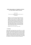
HANG06, HALP05, &
HAC1PS01 thru 10 Kits
High Altitude Conversion
Installation Instructions
ATTENTION INSTALLING PERSONNEL:
As a professional installer you have an obligation to
know the product better than the customer. This
includes all safety precautions and related items.
Remember, it is your responsibility to install the
product safely and to know it well enough to be able
to instruct a customer in its safe use.
Prior to actual installation, thoroughly familiarize
yourself with this Instruction Manual. Pay special
attention to all safety warnings. Often during installation or repair it is possible to place yourself in a
position which is more hazardous than when the unit
is in operation.
Safety is a matter of common sense...a matter of
thinking before acting. Most dealers have a list of
specific good safety practices...follow them.
The precautions listed in this Installation Manual
should not supersede existing practices but should
be considered as supplemental information.
RECOGNIZE THIS SYMBOL AS A SAFETY PRECAUTION.
THE INSTALLATION AND SERVICING OF THIS EQUIPMENT SHOULD BE PERFORMED ONLY BY QUALIFIED, EXPERIENCED TECHNICIANS.
IN CANADA “THE CONVERSION SHALL BE CARRIED OUT IN ACCORDANCE WITH THE REQUIREMENTS
OF THE PROVINCIAL AUTHORITIES HAVING JURISDICTION AND IN ACCORDANCE WITH THE REQUIREMENTS OF THE CAN/CGS B149.1 AND B149.2 INSTALLATION CODE.”
WARNING
Kit Includes:
This conversion kit shall be installed by
a qualified agency in accordance with
the manufacturer’s instructions and all
applicable codes and requirements of
the authority having jurisdiction. If the
information in these instructions is not
followed exactly, a fire, explosion or production of carbon dioxide may result
causing property damage, personal injury or loss of life. The qualified service
agency performing this work assumes
responsibility for the proper conversion
of this appliance with this kit.
Effective: October 1994
HANG06 (High Altitude Natural Gas) - installation
instructions, orifices, wire ties.
HALP05 (High Altitude Propane) - installation instructions, propane orifices, valve conversion kits with
instructions, conversion rating plate, conversion
date certificate, wire ties, and screen/turbulator
removal warning tag.
HAC1PS** (High Altitude Catagory 1 Pressure Switch)
- installation instructions, pressure switch.
Amana Refrigeration, Inc.
Fayetteville,
1 TN 37334
10759901
I. DESCRIPTION
is based on non-derated gas (about 1000 BTU/FT3 for
natural gas, and 2500 BTU/Ft3 for propane gas). If your
gas supply has been derated for the altitude, contact
your gas supplier for orifice sizing.
These kits are required when installing Amana Air Command 80 SSE and SV furnaces (GUIA, GCIA, GUIB, and
GCIB) at altitudes above 7500 ft. Above this altitude, a
derating of the appliance must be followed since the
CFM moved by the induced draft and blower fans remain
almost constant while the pounds of oxygen in that air is
reduced as the altitude increases. If this procedure is not
followed and the fuel input is not reduced, combustion
can be inefficient, incomplete or can possibly result in
premature failure of the heat exchanger due to an
excessive temperature rise.
Do not derate by adjusting the manifold pressure to a
lower pressure reading than what is specified on the
furnace nameplate. With a lower density of air and a
lower manifold pressure at the burner orifice, the orifice
will not aspirate the proper amount of air into the burner.
This can cause incomplete combustion of the gas,
flashback, and/or possible yellow tipping.
In addition to using smaller orifices to reduce the fuel
input, a different pressure switch must be used at
altitudes above 7500 feet because of the reduced air
density. This is required regardless of the heat content of
the fuel used.
The orifices in the high altitude kits have been selected
as a result of testing with the American Gas Association.
They will provide appropriate derating at altitudes above
7500 feet for proper furnace performance. The selection
Nat. Gas
Derates HAC1PS HAC1PS HAC1PS HAC1PS HAC1PS HAC1PS HAC1PS HAC1PS HAC1PS HAC1PS
(See Exp.
01
02
03
04
05
06
07
08
09
10
Sec. V)
GUIA/B045
7500-9500 ft
9500-11000 ft
GUIA/B070
7500-9500 ft
9500-11000 ft
GUIA/B090
7500-9500 ft
9500-11000 ft
GUIA/B115
7500-9500 ft
9500-11000 ft
GUIA/B140
7500-9500 ft
9500-11000 ft
GCIA/B045
7500-9500 ft
9500-11000 ft
GCIA/B070
7500-9500 ft
9500-11000 ft
GCIA/B090
7500-9500 ft
9500-11000 ft
GCIA/B115
7500-9500 ft
9500-11000 ft
GCIA/B140
7500-9500 ft
9500-11000 ft
PRESSURE SW.
SETTINGS "W.C.
34±4%
42±4%
X
X
X
X
33±4%
41±4%
X
X
31±4%
38±4%
X
27±4%
34±4%
X
X
25±3%
30±3%
X
X
X
34±4%
42±4%
X
X
33±4%
41±4%
X
X
31±4%
38±4%
X
27±4%
34±4%
X
X
25±3%
30±3%
X
-1.42
-1.30
-1.20
-1.14
-1.10
-1.05
-1.00
-0.95
TABLE 1 - PRESSURE SWITCH KITS (CATEGORY I VENTING ONLY)
2
-0.89
-0.85
II. PRESSURE SWITCH INSTALLATION
CAUTION
The gas supply must be shut off prior to
disconnecting the electrical power, before proceeding with the conversion.
1. Remove pressure switch. (Requires removing two
mounting screws, disconnecting rubber hose and disconnecting wiring.) See Fig. 1 for typical location.
CAUTION
To avoid the risk of fire, property damage, or personal injury, if disconnecting
wires on the pressure switch, make certain to reconnect the wires in the same
location.
FIGURE 2
-
GAS MANIFOLD REMOVAL
2. Replace natural gas orifices (Fig. 3A & 3B) with the
correct orifice kit depending on propane or natural
gas usage and the altitude at the installation site.
Refer to Tables 2 or 3 for the appropriate kit required.
FIG. 1 - PRESSURE SWITCH
FIGURE 3A
-
REPLACING GAS ORIFICES
2. Install the pressure switch provided in this kit. See
Table 1 for the appropriate kit needed.
3. Reconnect the hose. Reconnect all wires. Verify
wiring on the wiring diagram located inside the blower
compartment access panel.
4. Proceed with orifice installation.
FIGURE 3B - ORIFICES
III. ORIFICE INSTALLATION
CAUTION
The gas supply must be shut off prior to
disconnecting the electrical power, before proceeding with the conversion.
KIT NO.
ALTITUDE (ft.)
ORIFICE
HANG06
7500 to 11000
# 45
Table 2: Natural Gas Orifice Kits*
* This table assumes non-derated natural gas (about
1000 Btu/ft3). If your gas supply has been derated for the
altitude, contact your gas supplier for orifice sizing.
1. Remove the gas manifold by removing the burner
box front cover, cutting the wire ties, disconnecting
the gas valve low voltage wires, and removing the
four manifold mounting screws. See Figure 2.
3
IV. PROPANE GAS CONVERSION
KIT NO.
ALTITUDE (ft.)
ORIFICE
HALP05
7500 to 11000
# 56
WARNING
PERSONAL INJURY HAZARD
If your propane gas furnace is installed
in a basement, an excavated area or a
confined space, we strongly recommend
that you contact your propane supplier
about installing a warning device that
would alert you to a gas leak.
Table 3: Propane Gas Orifice Kits
4. Tighten orifices with a box-end wrench. Do not use a
socket wrench, as it could damage the orifices. Do not
overtighten. Do not cross thread.
.... Propane gas is heavier than air and any
leaking gas can settle in any low areas
or confined spaces.
CAUTION
To prevent premature heat exchanger failure,
follow the instructions below to remove all metal
inserts from the heat exchanger tubes during
propane conversions.
.... Propane gas odorant may fade, making the gas undetectable except with a
warning device.
5. If converting to propane gas, remove metal screen
inserts, where present, from the entrance of the heat
exchanger tubes. See Figure 4 and follow the a,b,c
directions.
An undetected gas leak would create a
danger of explosion or fire. If you suspect the presence of gas, follow the instructions on the cover of the furnace
installation manual. Failure to do so could
result in SERIOUS PERSONAL INJURY
OR DEATH.
WARNING
PERSONAL INJURY HAZARD
Iron oxide (rust) can reduce the level of
odorant in propane gas. A gas detecting
device is the only reliable method to
detect a propane gas leak. Contact your
propane supplier about installing a gas
detecting warning device to alert you in
the event that a gas leak should develop.
FIGURE 4 - REMOVAL OF METAL SCREEN
INSERTS
a) Remove entire burner box assembly, including
burners, from the partition panel as one unit.
Failure to detect a propane gas leak
could result in an EXPLOSION or FIRE
which could cause SERIOUS PERSONAL
INJURY OR DEATH.
b) Hold assembly and remove the screen retention
plate and tube inserts from each section of the heat
exchanger.
c) Reinstall the retention plate and entire burner box
assembly.
CAUTION
To prevent unsatisfactory furnace operation, the proper gas conversion kit
must be used for each valve. Use the
White-Rodgers spring kit only with the
White-Rodgers gas valve and use the
Honeywell spring kit only with the Honeywell gas valve. THE SPRING KITS ARE
NOT INTERCHANGEABLE.
6. Reinstall the gas manifold and reconnect the gas
valve low voltage wiring. Install new wire ties making
sure that wires do not droop between orifices and
burners.
7. If converting to propane gas, see PROPANE GAS
CONVERSION section for additional instructions. If
remaining on natural gas, skip to OPERATIONAL
CHECK.
4
IMPORTANT: Propane gas is heavier than air and does
not vent upward as with natural gas fuels.
sion kit. If the unit is equipped with a White-Rodgers
36E gas valve, (Figure 5a), use Spring Kit #92-0659
(Figure 5b). If the unit is equipped with a Honeywell
VR8205 gas valve, (Figure 6a), use Spring Kit #393691
(Figure 6b). In each case, change the regulator spring
per instructions included with that particular regulator
spring. Discard whichever spring kits are not used.
1. IMPORTANT: Remove the metal inserts from the
entrance of all heat exchanger tubes, as shown in
Fig. 4. This should be done as part of the “ORIFICE
INSTALLATION” procedure.
2. Replace the gas valve regulator spring with one of
two new springs included in this propane gas conver-
3. Attach label shown in Figures 5B or 6B, to gas valve
indicating propane conversion.
FIGURE 6A HONEYWELL VR8205 GAS VALVE
FIGURE 5A WHITE-RODGERS 36E GAS VALVE
FIGURE 5B WHITE-RODGERS SPRING KIT
FIGURE 6B HONEYWELL SPRING KIT
V. OPERATIONAL CHECK
4. CHECK GAS INPUT AND PRESSURES
Check inlet gas pressure. With the power and gas off,
connect a water manometer or adequate gauge to the
“inlet pressure tap” of the gas valve. With the power
and gas on, put the furnace into heating cycle and turn
on all other gas consuming appliances. For natural
gas, the inlet gas pressure should be between 5.0 and
10.0 inches of water. For propane gas the inlet gas
pressure should be between 11.0 and 14.0 inches of
water.
1. Start the furnace using the procedures in the section,
“Operating Your Furnace” in the installation instructions. In addition, perform the following checks and
adjustments.
2. The position of the ignitor, relative to the burner, is not
effected by this conversion procedure but the ignitor
should be visually inspected for any damage at this
point.
3. CHECK FOR LEAKS. Leak check the orifice threads
by using a soap solution. Reinstall the burner box
cover.
5. CHECK THE MANIFOLD PRESSURE
A tapped opening (“Manifold Pressure Tap” in Figures 5A or 6A) is provided in the gas valve to facilitate
measurement of the manifold pressure. A “U Tube”
manometer having a scale range from 0 to 12 inches
of water should be used for this measurement. The
manifold pressure must be measured with the burners operating and the burner box cover in place.
WARNING
To avoid the risk of fire or explosion, do
not use a flame to check for leaks.
5
7. CHECK THE GAS INPUT - PROPANE GAS
Verify the gas input rate by checking that the appropriate orifices have been installed and the manifold
pressure has been set as stated in these instructions.
To adjust the pressure regulator, remove the adjustment screw or cover on the gas valve. Turn out
(counterclockwise) to decrease pressure, turn in
(clockwise) to increase pressure. (“Manifold Pressure
Adjustment” in Figs. 5A or 6A). Only small variations
in gas flow should be made by means of the pressure
regulator adjustment. For natural gas, the manifold
pressure must be between 3.2 and 3.8 inches water
column (3.5” nominal). For propane gas, the manifold pressure must be between 9.7 and 10.3 inches
water column (10.0” nominal). Any major changes in
flow must be made by changing the size of the burner
orifices.
8. CHECK BURNER FLAMES
Check burner flames through the view port in the
burner box. Flames should be stable, soft and blue,
(dust may cause orange tips but they must not be
yellow). They should extend directly outward from the
burners without curling, floating, or lifting off.
9. Check the normal operating sequence of the ignition
system to insure burners light properly.
6. CHECK THE GAS INPUT - NATURAL GAS
10. CHECK TEMPERATURE RISE
To measure the gas input using the gas meter, proceed
as follows:
NOTE: The relationship between external static pressure and temperature rise will be different than is shown
in the installation instructions, while the relationship
between CFM and temperature rise will be approximately the same. Temperature rise must still be within
the limits shown on the unit nameplate.
a. Turn off gas supply to all other appliances except
the furnace.
b. With the furnace operating, time the smallest dial on
the meter for one complete revolution. If this is a 2
cubic foot dial, divide the seconds by 2; if it is a 1
cubic foot dial, use the seconds as is. This gives the
seconds per cubic foot of gas being delivered to the
furnace.
Check the temperature rise through the unit by placing
thermometers in supply and return air registers as
close to the furnace as possible. Thermometers must
not be able to “see” the furnace heat exchanger, or
false readings could be obtained.
c. INPUT = (GAS HTG VALUE) x (3600) ÷ (SEC. PER
CUBIC FOOT)
All registers must be open; all duct dampers must be
in their final (fully or partially open) position, and the
unit operated for 15 minutes before taking readings.
Example: Natural gas with a heating value of 1000
BTU per cubic foot and 34 seconds per cubic foot as
determined by Step 2, then:
The temperature rise must be within the range specified on the rating plate.
Input = 1000 x 3600 ÷ 34 = 106,000 BTU per Hour
NOTE: Air temperature rise is the temperature difference between supply and return air.
NOTE: BTU content of the gas should be obtained
from the gas supplier. (3600 is a conversion factor
between seconds and hours).
If the correct temperature rise is not obtained, it may be
necessary to change the blower speed. A higher blower
speed will lower the temperature rise. A slower blower
speed will increase the temperature rise.
This measured input must agree with the derates for
your unit and elevation as indicated in Table 1 on page
2.
If it is necessary to adjust the blower speed, consult the
furnace installation manual for details.
Derating Example 1: GUIA115A40 at 8500 ft.
Sea level input = 115000 BTU/Hr.
From Table 1: Derate at 8500 ft. = 27±4%
11. For propane gas conversions, attach conversion
data plate, with correct input rating, adjacent to the
unit rating plate and post “conversion date certificate” adjacent to the furnace.
Since we are at the mid point of the evevation range,
we use the mid point of the derate; 27%.
New Input = 115000 x (1 - .27) = 83950 BTU/Hr
COMPLETE THE INSTALLATION
Derating Example 2: GUIA115A40 at 7500 ft.
Sea level input = 115000 BTU/Hr.
From Table 1: Derate at 7500 ft. = 27±4%
See the furnace installation manual for all installation
details which were not covered in this booklet.
Since we are at the lower end of the elevation range,
we use the lower derate; (27 - 4) = 23%
New Input = 115000 x (1 - .23) = 88550 BTU/Hr
d. Relight all other appliances turned off in step a. Be
sure all pilot burners are operating.
6