1
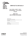
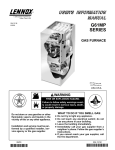
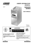
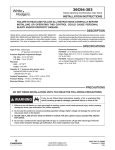
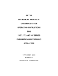
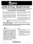
SUPPLEMENTAL INSTRUCTIONS
50/75/100 MBH
GAS CONVERSION INSTRUCTIONS
AND HIGH ALTITUDE MANIFOLD PRESSURE ADJUSTMENT FOR
ALUMINUM BLOCK BOILERS
EFFECTIVE DATE SEPTEMBER 1, 2012
Please read these instructions carefully before starting the adjustment or conversion process. These
changes must be performed by a qualified service agency.
! DANGER
Before servicing, turn off electrical power to boiler
at service switch. Close manual gas valve to turn
gas supply OFF to boiler. Failure to comply will result
in death or serious injury.
HIGH ALTITUDE
MANIFOLD PRESSURE ADJUSTMENT
1. Turn off manual gas valve.
2. Remove manifold pressure tap plug marked “Outlet
Figure 1 - Gas Valve Detail
PRESSURE REGULATOR
ADJUSTMENT (UNDER CAP SCREW)
WIRING TERMINALS (2)
VR8205
OUTLET
PRESSURE
TAP
INLET
PRESSURE
TAP
OUTLET
INLET
ON
OFF
Pressure Tap” from gas valve using 3/16” Allen wrench.
Install ⅛” NPT x ¼” barbed fitting. See Figure #1
3. Connect manometer or gauge to gas valve pressure
tap barbed fitting just installed in step 1. Manometer
should be capable of reading 1 to 15 inches of water
column. See Figure #2.
4. Turn electrical power and gas supply on. Set
thermostat high enough to start boiler.
5. Start boiler.
6. Note gas manifold pressure on manometer or gauge.
Manometer or gauge reading should be 2½ inches
water column at start up.
7. To adjust manifold pressure, remove “Pressure
9. Once correct pressure reading is obtained and remains
steady, shut off boiler at thermostat, shut off manual
gas valve, and electrical supply. Remove manometer or
gauge, ⅛” barbed fitting and replace pressure tap plug.
10. Restore electrical and gas supply, restart boiler and
check for gas leaks using soapy water or a commercial
leak detector.
11. Fill out data on adjustment/conversion label and attach
to inside left panel of boiler.
Operate boiler through at least 6 ignition cycles to check for
proper operation of boiler before leaving job site.
Regulator Adjustment Cap” located on gas valve
to gain access to regulator adjustment screw. Turn
adjustment screw clockwise to increase pressure and
counterclockwise to decrease pressure. See Figure
#1.
NOTICE
When doing this procedure, place pressure regulator
cap back in place to obtain correct reading. Not
putting cap in place gives false reading of manifold
pressure.
8. Adjust manifold pressure to indicated value using
known gas Btu value and known altitude of installation.
See Tables #1 and #2 on following pages.
P/N 240009672, Rev. D [06/2013]
HIGH ALTITUDE RATINGS FOR NATURAL GAS
See Tables #1 and #2 for specific high altitude orifice information.
Altitude in Ft.
Normal Input (MBH)
Combustion Setting (CO2)
Gas Orifice
Burner Plate
Altitude in Ft.
Normal Input (MBH)
Combustion Setting (CO2)
Gas Orifice
Burner Plate
Altitude in Ft.
Normal Input (MBH)
TABLE #1: NATURAL GAS
MODELS 050 MBH
Stock Factory
Btu Value of Natural Gas++
Settings
750
850
950
1000
0-5,000
5,000-10,000
50
–
–
–
–
8.7 - 9.7% (CO < 100 ppm)
43331094
109006405
MODELS 075 MBH
Stock Factory
Btu Value of Natural Gas++
Settings
750
850
950
1000
0-5,000
5,000-10,000
75
–
–
–
1050
–
1050
–
–
8.7 - 9.7% (CO < 100 ppm)
43331092
109006406
MODELS 100 MBH
Stock Factory
Btu Value of Natural Gas++
Settings
750
850
950
1000
0-5,000
5,000-10,000
100
–
–
–
1050
–
–
8.7 - 9.7% (CO < 100 ppm)
43331090
109009105
Combustion Setting (CO2)
Gas Orifice
Burner Plate
++Contact local gas utility or distributor for Btu value of gas.
Gas Conversion Procedure
When changing from Natural to Propane or vice
versa, use correct conversion orifice for boiler
model.
1. Turn off manual gas valve.
2. Remove front door. Use 5/16” nut driver to
remove top panel.
3. Use 9/64” Allen wrench to remove adapter
block from gas valve. Take care not to lose
o-ring under the block. See Figure #3.
4. Use adjustable or 1¼” wrench on bushing
to remove gas orifice assembly from mixer
turning counter clockwise. Do not use
channel locks, pipe wrench, etc, as damage
to bushing may occur. See Figure #2.
5. Use small pipe wrench to remove orifice
from bushing by turning counter clockwise.
Install correct orifice for boiler being
converted. Apply small amount of pipe dope
to threads of orifice leaving last two threads
clean. Turn clockwise into bushing.
Figure 2 - Gas Assembly and Inlet Air Assembly
GAS VALVE VENT
PRESSURE REGULATOR
ADJUSTMENT
(UNDER COVER SCREW)
OFF
C
ON
OUTLET PRESSURE TAP
(1/8" PLUG)
BUSHING
4-WAY CONNECTOR
MIXER
TO PRESSURE SWITCH
WHITE TRANSPARENT
VINYL TUBING
PRESSURE
REFERENCE PRESSURE
DIFFERENTIAL
PRESSURE
GAUGE
2
U-TUBE
MANOMETER
HIGH ALTITUDE RATINGS FOR PROPANE
Altitude in Ft.
Normal Input (MBH)
TABLE #2: PROPANE GAS
MODELS 050 MBH
Stock Factory
Btu Value of Propane Gas++
Settings
2300
2350
2400
2450
0-5,000
5,000-10,000
–
–
–
–
50
Orifice
10.0 -11.1% (CO < 100 ppm)
43331095
Burner Plate
109006405
Combustion Setting (CO2)
MODELS 075 MBH
Stock Factory
Btu Value of Propane Gas++
Settings
2300
2350
2400
2450
Altitude in Ft.
Normal Input (MBH)
Combustion Setting (CO2)
Orifice
Burner Plate
0-5,000
75
–
–
5,000-10,000
–
–
2500
–
2500
–
10.0 -11.1% (CO < 100 ppm)
43331096*
109009107
43331093
* For model 075 LP units only at altitudes above 5,000 ft., install 075 MBH High Altitude Orifice Kit #5550002629 which includes
43331096 orifice.
MODELS 100 MBH
Stock Factory
Settings
Altitude in Ft.
0-5,000
Normal Input (MBH)
100
Btu Value of Propane Gas++
2300
2350
2400
2450
2500
–
–
5,000-10,000
–
–
–
Combustion Setting (CO2)
10.0 -11.1% (CO < 100 ppm)
Orifice
Burner Plate
43331091
109009105
++Contact local gas utility or distributor for Btu value of gas.
6. Apply pipe dope to bushing threads. Install gas orifice
Figure 3 - Gas Valve Adapter Detail
7.
8.
9.
10.
11.
assembly turning clockwise into mixer. DO NOT USE
TEFLON TAPE.
Attach adapter block to gas valve.
75 MBH: Chose table for correct type of fuel supplied
to your boiler. Replace burner plate with plate listed in
correct table. Different burner plate is used for Nat and
LP fuels.
Install top panel. Restore electrical and gas supply. Set
thermostat high enough to start boiler. Restart boiler.
Check for gas leaks using soapy water or commercial
leak detector.
Fill out data on adjustment/conversion label. Attach to
inside left panel of boiler.
Install front door.
Operate boiler through at least 6 ignition cycles to check for
proper operation of the boiler before leaving job site.
3