1
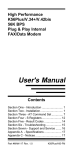
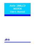
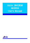
Atrie 33.6K
MODEM
User's Manual
ATRIE 336RE
MODEM
USER'S MANUAL
ATRIE TECHNOLOGY INC.
10 Floor,14 , Lane 609, Sec.5, Chung Hsin Rd.,
San Chung City, Taipei Hsien, Taiwan 241, R.O.C.
TEL:+886-2-29995155 FAX:+886-2-29994960
th
(C) Copyright 2000 ATRIE TECHNOLOGY INC.
CONTENTS
CHAPTER 1 INTRODUCTION
Features----------------------------------------------------------------1
Package Contents-----------------------------------------------------1
Modem Panel Description------------------------------------------2
DIP Switch------------------------------------------------------------3
CHAPTER 2 AT COMMAND GUIDELINES
AT Command Set----------------------------------------------------6
CHAPTER 3 V.25bis COMMAND
V.25bis Command set----------------------------------------------15
V.25bis Result Code-------------------------------------------------16
CHAPTER 4 REGISTERS
S Register Summary------------------------------------------------17
APPENDIX A SPECIFICATIONS--------------------19
APPENDIX B RESULT CODES----------------------21
CHAPTER 1
INTRODUCTION
This manual is written for 33600bps dial-up/leased line modem.
Features
* Compatible with BELL 103, 212A standards and ITU-T V.21,
V.22, V.23, V.22bis, V.32, V.32bis, V.FC, V.34, V.8, V.25bis,
V.42, V.42bis recommendation.
* Provides MNP4, ITU-T V.42 error correction and MNP5,
ITU-T V.42bis data compression.
* Provides ITU-T V.8 and Multi-mode handshake according to
ITU-T recommendation.
* Utilizes full duplex asynchronous transmission with a
maximum effective throughput of 115200bps.
* Provides 2 wire full duplex dial up line and leased line
operation.
* Asynchronous and synchronous operation selectable on both
DIP switch or AT command.
* Provides auto-dial, auto-answer, redial, and full call progress
monitoring functions.
* Provides Microcom Networking Protocol (MNP) Class 10 to
ensure best performance during Cellular Phone communication.
* Supports GIII Fax with EIA Class 1 and Class 2 command and
ITU-T V.17.
Package Contents
Carefully unpack the product package that you have received. T
he following is a checklist of the package:
* The modem
* One AC power adapter
* One RJ-11 telephone cable
* One Userís Manual
1
If there is any wrong, missing or damaged part, please contact
your dealer.
Modem Panel Description
Modem Front Panel
Dial -up/l eased l in e
MR
TR
SQ
336RE
CD
RD
TD
OH
EC
Figure 1-1 Modem Front Panel
LED Indicators
MR
Power and Test Indicator
This LED indicator indicates three conditions:
1.Flashes when the modem is error in power on self-test.
2.Lights ON when the power is applied to the modem.
3.Flashes when the modem is in the loop back test.
TR
SQ
CD
RD
TD
Terminal Ready
Lights up when the computer or terminal is ready to receive
data.
Signal Quality
Indicates the signal quality of the telephone line. Describes
below:
ON
-- Good
FLASH -- Medium
OFF
-- Poor
Carrier Detect
Lights up when carrier signal from a remote modem is
detected.
Receive Data
Flashes when the local DTE receives data from the modem.
Transmit Data
Flashes when the local DTE (Data Terminal Equipment)
transmits data into the serial port of the modem.
2
OH
EC
Off-Hook
Lights up when off-hook.
Error Correction
When configure to error correction mode in command mode
When making a protocol link (V.42 or MNP4) with remote
modem in data mode.
Modem Rear Panel
POWER
SW1
SERIAL PORT
AC
SW2
LINE
Figure 1-2 Modem Rear Panel
POWER
AC
Power switch
The power source input. Put the other end into the
wall outlet of the AC power source.
SERIAL PORT The RS-232 serial port. Use the RS-232C cable to
connect the modem and the computer or terminal.
LINE
The jack allows user to connect the telephone line
to the modem.
Dip Switch
1
ON
2
3
4
SW1
SW1
5
6
7
8
9
10
11
12
1
ON
2
SW2
The 12-position DIP Switch
POSITION 1, 2 - Operation and line type selection
1
2
ON
ON Power on operation
OFF
ON V.25bis operation
ON
OFF dumb mode operation
OFF
OFF AT command operation
3
POSITION 3 - Asynchronous/Synchronous Operation selection
ON
Synchronous operation
OFF
Asynchronous operation
POSITION 4, 5, 6, 7 - The DTE Speed selection
4
5
6
7
DTE Speed
ON
ON
ON
ON 1200bps
OFF
ON
ON
ON 2400bps
ON
OFF
ON
ON 4800bps
OFF
OFF
ON
ON 7200bps
ON
ON
OFF
ON 9600bps
OFF
ON
OFF
ON 12000bps
ON
OFF
OFF
ON 14400bps
OFF
OFF
OFF
ON 16800bps
ON
ON
ON
OFF 19200bps
OFF
ON
ON
OFF 21600bps
ON
OFF
ON
OFF 24000bps
OFF
OFF
ON
OFF 26400bps
ON
ON
OFF
OFF 28800bps
OFF
ON
OFF
OFF 38400bps
ON
OFF
OFF
OFF 57600bps
OFF
OFF
OFF
OFF 115200bps
POSITION 8, 9, 10, 11 - The Line Speed (DCE Speed) selection
8
9
10
11 Line Speed (DCE Speed)
ON
ON
ON
ON 300bps (V.21)
OFF
ON
ON
ON 1200/75bps (V.23)
ON
OFF
ON
ON 1200bps (V.22/Bell 103)
OFF
OFF
ON
ON 2400bps (V.22 bis)
ON
ON
OFF
ON 4800bps (V.32/ V.32 bis)
OFF
ON
OFF
ON 7200bps (V.32 bis)
ON
OFF
OFF
ON 9600bps (V.32/ V.32 bis)
OFF
OFF
OFF
ON 12000bps (V.32 bis)
ON
ON
ON
OFF 14400bps (V.32 bis)
OFF
ON
ON
OFF 16800bps (V.34)
ON
OFF
ON
OFF 19200bps (V.34)
OFF
OFF
ON
OFF 21600bps (V.34)
ON
ON
OFF
OFF 24000bps (V.34)
4
OFF
ON
OFF
OFF
ON
OFF
OFF
OFF
OFF
OFF
OFF
OFF
26400bps (V.34)
28800bps (V.34)
Line speed follow DTE speed
POSITION 12 ñ DIP switch/NVRAM selection
ON
Loads DIP switch for power on configuration.
OFF
Loads NVRAM for power on configuration.
SW2
The 2-position DIP Switch
Position
1
State
ON
OFF
2
ON
OFF
Description
Answer mode
Originate mode
Leased Line Operation
Dial-up Operation
5
CHAPTER 2
AT COMMAND GUIDELINES
AT Command Set
ATA
A/
ATBn
ATB0
ATB1
ATDs
Manual Answer
Force modem to go off-hook and answer an incoming call.
Repeat Last Command
There is no need to type <Enter>, after the "/" has typed,
the modem executes the last executed command
immediately.
Select ITU-T/BELL Mode (for 300 and 1200 bps only)
Selects ITU-T (Default)
Selects BELL
Dial
String s
0-9
*, #, A,B,C,D
-( )
P
T
J
K
L
R
S=n
W
&
,
;
@
!
^
ATEn
ATE0
Description
Dialing digits
DTMF dialing digits
Ignored by modem
pulse dial
Tone dial
Perform MNP10 link negotiation at 1200bps
Enable power level adjustment during MNP10
link negotiation
Re-dial last number
Reverse originate mode
Dial NVRAM telephone number (n = 0 to 3).
Wait for dial tone
Wait for AT&T îbongî tone for credit card
dialing before continuing with the dial string
Pause
Return to command state
Wait for quiet answer
Flash hook
Calling tone
Echo Command
Disables command echo
6
ATE1
ATHn
ATH0
ATH1
ATIn
ATI0
ATI1
ATI2
ATI3
ATI4
ATI5
ATI6
ATLn
ATL0
ATL2
ATL3
ATMn
ATM0
ATM1
ATM2
ATM3
ATNn
ATN0
ATN1
ATN3
ATOn
ATO0
ATO1
ATQn
ATQ0
ATQ1
ATSr=n
Enables command echo (Default)
Hook on/off
On-hook
Off-hook
Identification Command
Reports product code
Reports ROM checksum
Verify the checksum of ROM. If correct, reports "OK"; if
not reports "ERROR".
Reports ROM revision
Reports model name, ROM revision, issue date.
Reports region code
Reports DATA PUMP revision
Speaker Volume Control
Low speaker volume(Default)
Medium speaker volume
High speaker volume
Speaker Control
Speaker always off.
Speaker on until the modem receives a carrier. (Default)
Speaker always on.
Speaker off while dialing, then on until the modem
receives a carrier .
Set Multi- or Fix- Mode Handshake
Fix-mode handshake. The connection speed depends on
the DTE speed or register S37.
Multi-mode handshake. Follows the recommendation of
ITU-T multi-mode handshake. It can automatically chan
ge the line speed to make most efficient connection.
(Default)
Same as ATN1 but without V.23 mode.
Return to On-Line Mode
Returns on-line data mode without a retrain.
Returns on-line data mode with a retrain.
Result Code Command
Enables the modem to report result codes (Default)
Disables the modem to report result codes.
Read/write S-register
7
ATSr=n
ATSr?
Sets S-register r to the vale n
Read the content of S-register r
ATVn
ATV0
ATV0
ATWn
ATW0
ATW1
Result Code Type
Selects short (digit) form result codes.
Selects long (verbose) form result codes. (Default)
Negotiation Progress Message Command
Upon connection, reports the DTE speed. (Default)
Upon connection, reports the line speed, the error
correction protocol, and the DTE speed.
Upon connection, reports the DCE speed.
Extended Result Codes
The modem ignores dial tone and busy tone when
dialing. Sends standard result codes when a connection
is made.
The modem ignores dial tone and busy tone when
dialing. Sends extended result codes when a connection
is made.
The modem detects dial tone when dialing. Sends
extended result codes when a connection is made.
The modem detects busy tone. Sends extended result
codes when a connection is made.
The modem detects dial tone and busy tone. Sends
extended result codes when a connection is made.
(Default)
Long Space Disconnect
Disables the long space disconnect feature. (Default)
Enables the long space disconnect feature.
Reset Command
Reset and load restore profile n, where n = 0~3.
The Escape Code
The Escape Code forces the modem to the command
mode from the data mode, without releasing the line
connection.
Serial Port DCD Control
Sets CD always ON
Sets CD to follow the state of carrier (Default)
Sets CD ON except during disconnect (3~5 sec.)
Serial Port DTR Control
Assumes DTR ON.
ATW2
ATXn
ATX0
ATX1
ATX2
ATX3
ATX4
ATYn
ATY0
ATY1
ATZn
+++
AT&Cn
AT&C0
AT&C1
AT&C2
AT&Dn
AT&D0
8
AT&D1
AT&D2
AT&D3
AT&Fn
AT&Gn
AT&G0
AT&G1
AT&G2
AT&Kn
AT&K0
AT&K1
AT&K2
AT&K3
AT&K4
AT&K5
AT&K6
AT&K7
AT&K8
AT&Ln
AT&L0
AT&L1
AT&Mn
AT&M0
AT&M1
AT&M2
AT&M3
AT&Pn
Enters command mode on detecting ON-to-OFF
transition of DTR.
Goes ON-HOOK on detecting ON-to-OFF transition of
DTR. (Default)
Resets the modem on detecting ON-to-OFF transition of
DTR.
Restore Factory Configration(Profile)
Restore factory configration n, where n = 0~9.
Select Guard Tone
Disables guard tone (Default)
Selects 550 Hz guard tone
Selects 1800 Hz guard tone
Serial Port Flow Control
Disables flow control.
Enables unidirectional RTS/CTS hardware flow control.
Enables unidirectional XON/XOFF software flow control.
Enables bi-directional RTS/CTS hardware flow control.
(Default)
Enables bi-directional XON/XOFF software flow control.
Enables transparent XON/XOFF software flow control.
Enables both RTS/CTS and XON/XOFF flow control.
Enables bi-directional DTR/DSR hardware flow control.
Enables unidirectional DTR/DSR hardware flow control.
Line Type Select
PSTN line operation. (Default)
leased line operation
Asynchronous/Synchronous Mode Selection
Selects asynchronous operation. (Default)
Selects synchronous data mode with Async. off-line
command mode.
Selects synchronous data mode with Async. off-line
command mode. Same as &M1 except that &M2
enables DTR dialing of stored telephone number at
location 0.The modem will disconnect if DTR is OFF
for more than the time period in register S25.
Selects synchronous data mode. The call is manually in
itiated while DTR is inactive. The handshake is
proceeding when DTR becomes active.
Select Pulse Dial Make/Break Ratio
9
AT&P0
AT&P1
AT&P2
AT&P3
AT&Qn
AT&Q0
AT&Q1
AT&Q2
AT&Q3
AT&Q5
AT&Q6
AT&Rn
AT&R0
AT&R1
AT&Sn
AT&S0
AT&S1
AT&S2
AT&Tn
AT&T0
AT&T1
AT&T3
AT&T4
AT&T5
AT&T6
AT&T7
AT&T8
AT&Un
AT&U0
AT&U1
AT&V
AT&Wn
AT&Xn
AT&X0
39%-61% Make/Break ratio at 10 pulses/second.
(Default)
33%-67% Make/Break ratio at 10 pulses/second.
39%-61% Make/Break ratio at 20 pulses/second.
33%-67% Make/Break ratio at 20 pulses/second.
Select Communication Mode
Communicates in direct asynchronous mode.
Refers to the command AT&M1
Refers to the command AT&M2
Refers to the command AT&M3
Communicates in error correction mode. (Default)
Communicates in asynchronous data operation with
normal speed buffered mode.
Serial Port RTS/CTS Option Command
CTS follows RTS at all time (Default)
Assumes CTS always on
Serial Port DSR Control Command
DSR remains ON at all time (Default)
DSR follows the ITU-T recommendation
DSR follows carrier
Loop Test Functions
Ends loop test
Local analog loop back
Local digital loop back
Responds to remote digital loop back request (Default)
Ignores remote digital loop back request.
Initiates ITU-T remote digital loop back
Remote digital loop back with self-test
Local analog loop back with self-test
Trellis Coding Modulation Selection Command
Enables trellis coding modulation (Default)
Disables trellis coding modulation
View Profiles and Stored Telephone Number
This command shows the active configuration, and
fouruser profiles.
Store Current Configuration
Saves current configuration at user profile n, including
commands and registers, where n = 0~3.
Select Synchronous Clock Source
Selects internal clock. (Default)
10
AT&X1
AT&X2
AT&Yn
Selects external clock.
Selects slave receive clock.
Power On Profile Selection Command
Recalls profile n when power on, where n = 0~3.
AT&Zn=m Store Telephone Number
The n indicates the telephone number locations, where
n = 0~9.
The m is a dial string (refer to ATDs command) of up
to 35 characters. This command must be the last one
on a command line.
AT%Cn
Data Compression Protocol Selection
AT%C0
Disables data compression
AT%C1
Enables MNP5 error correction
AT%C2
Enables V.42bis data compression
AT%C3
Enables both MNP5 and V.42bis data compression
(Default)
AT%En
Retrain and Rate Negotiation Command
AT%E0
Disables auto retrain feature
AT%E1
Enables auto retrain feature
AT%E2
Enables auto retrain and rate negotiation with fall
back/forward feature (Default)
AT%L
Line Signal Level
Returns a value, which indicates the received signal
level. For example, 009 = -9 dBm, 043 = -43 dBm, and
so on.
AT%Q
Line Signal Quality
Reports the line signal quality. The line quality is
reported in three decimal digits, rang from 000(good)
to 128(poor).
AT%Rn
Ring Back Message Command
AT%R0
Disables ring back message (Default).
AT%R1
Enables ring back message
AT\An
Select Maximum MNP Block Size
The maximum MNP block size to be 64 characters
AT\A0
The maximum MNP block size to be 128 characters
AT\A1
The maximum MNP block size to be 192 characters
AT\A2
(Default)
AT\A3
The maximum MNP block size to be 256 characters
AT\Bn
Transmit Break to Remote
11
AT\F
AT\Gn
AT\G0
AT\G1
AT\Nn
AT\N0
AT\N1
AT\N2
AT\N3
AT\N4
AT\N5
AT\Rn
AT\R0
AT\R1
AT\S
AT*Kn
Transmit a break signal to the remote modem with a le
ngth in multiples of 100 ms according to parameter n s
pecified.
Where n = 1~9. (Default n = 3)
View Stored Telephone Number
Reports the content of the ten stored telephone
numbers.
Modem Port Flow Control
Disables modem port flow control (Default)
Enables modem port flow control
Operating Mode
Selects normal speed buffered mode.
Selects direct mode. (Forces &Q0)
Selects reliable (error-correction) mode. The modem
will first attempt a LAP-M connection and then an
MNP connection. Failure to make a reliable connection
results in the modem hanging up (Forces &Q5, S36=4,
and S48=7)
Selects auto reliable mode. This operates the same as \
N2 except failure to make a reliable connection results
in the modem falling back to the speed buffered
normal mode (Forces &Q5, S36=7, and S48=7)
(Default)
Selects LAP-M error-correction mode. Failure to make a
LAP-M error-correction results in the modem hanging
up.
(Forces &Q5 and S48=0) The AT-K1 command can over
ride the AT\N4 command.
Selects MNP5 error-correction mode. Failure to make a
n MNP error-correction connection results in the mode
m hanging up. (Forces &Q5, S36=4 and S48=128)
Serial Port Ring Indicator Control
The ring indicator ON for the duration of the telephone
call.
Turns OFF the ring indicator after the telephone call is
answered. (Default)
Modem Status Display
This command displays the active commend setting
and lists the command.
Keyboard Interrupt Command
12
AT*K0
AT*K1
AT+MS
Enables keyboard interrupt during handshake (Default)
Disables keyboard interrupt during handshake
Select Modulation
The command format is:
AT+MS=<mod>,<automode>,<min_rate>,
<max_rate>,<CR>
For example: AT+MS=10,1,1200,14400
** <mod> Parameter Definitions:
mod Modulation
Possible Rates(bps)
0 V.21
300
1 V.22
1200
2 V.22bis
2400, 1200
3 V.23
1200
9 V.32
9600, 4800
10 V.32bis
14400, 12000, 9600, 7200, 4800
11 V.34
33600, 31200, 28800, 26400, 24000, 21600,
19200, 16800, 14400, 12000, 9600, 7200,
4800, 2400
64 BELL 103
300
69 BELL 212
1200
74 V.FC
28800, 26400, 24000, 21600, 19200, 16800,
14400
** <mod> Parameter Definitions:
Automode
0
1
Option Selected
Auto mode disable
Auto mode enable using V.8 or multi-mode
(Default)
The following table are the explanation of the MNP10 command
set.
AT)Mn
AT)M0
AT)M1
Power Level Adjust Command
Disables power level adjustment during MNP 10 link
negotiation. The AT)M0 command will allow the
transmitter adjustment if cellular operation is
requested by the remote modem.(Default)
Enables power level adjustment during MNP 10 link
negotiation. NOTE: AT)M1 should not be used with
13
AT*Hn
AT*H0
AT*H1
AT*H2
AT-Kn
AT-K0
AT-K1
AT-Qn
AT-Q0
AT-Q1
AT@Mn
AT:En
AT:E0
AT:E1
AT*H2.
Link Negotiation Speed
Link negotiation occurs at the highest supported
speed. (Default)
Link negotiation occurs at 1200bps; used primarily for
establishing cellular connections.
Link negotiation occurs at 4800bps; used primarily to
negotiate an MNP 10 connection on less than average
quality telephone lines.
MNP Extended Services
Disables V.42 LAP-M to MNP 10 conversion. (Default)
Enables V.42 LAP-M to MNP 10 conversion.
Enable Fallback to V.22bis/V.22
Disables fallback to 2400 bps (V.22bis) and 1200 bps
(V.22). Fallback is enabled only to 4800 bps.
Enables fallback to 2400 bps (V.22bis) and 1200 bps
(V.22). (Default)
Initial Cellular Power Level Setting
Parameter n Initial Cellular Power Level
0
-26 dBm (Default)
1
-30 dBm
2~10
-10 dBm
11f≤f≤31
- n dBm
Compromise Equalizer Enable Command
Disables the equalizer
Enables the equalizer (Default)
14
CHAPTER 3
V.25bis COMMAND
V.25bis Command set
CRN n
Dialing Command
This command dials a telephone number specified by the
parameter "n". The "n" in this command is a dial string
which includes telephone number 0 to 9, and #, * for tone
dialing only, dial modifiers (please refer to ATDs
command). Any dial modifier specified in ATD command
is valid here in ITU-T V.25bis command mode. There are
four extra dial modifiers that V.25bis defined listed below:
: Same definition as "W" modifier in the ATD command.
< Same definition as "," modifier in the ATD command.
& Same definition as "!" modifier in the ATD command.
CRS n
PRN m;n
RLN
DIC
CIC
= Same definition as ";" modifier in the ATD command.
Dialing Stored Number Command
Dials the telephone number that previously stored in
memory location n. Where n = 0~9.
Stored Telephone Number in Location m
This command stores telephone number in memory
location m for later dialing. It is identical with the AT&Z
command in AT command mode. Where m = 0~9. The n
is a dial string of up to 35 characters. Valid dial string
characters are 0 to 9, dial modifiers, and for tone dialing
#, *.
Display the Stored Telephone Number
This command shows the ten (location 0 to 9) stored
telephone numbers.
Disregard Incoming Call
The DIC command disables the auto answer function of
the modem in ITU-T V.25bis operation mode.
Connect Incoming Call
15
CNL
This command enables the auto answer function of the
modem.
Execute AT Command
This command allows the user to issue and execute the
AT command while in the V.25bis command mode.
V.25bis Result Code
RESULT
CODE
CNX m
VAL
INV
INC
CFI m
LSN m;n
DESCRIPTION
Modem connects to the remote modem. The m indicates
the DCE speed.
Command valid and executed successfully.
Command error, can not be executed.
Ring signal detected.
Failure of dialing, the m represents the meanings below:
ET Line busy
RT No answer
CB Local modem busy
NT No carrier
NS Memory location is empty, no telephone number
stored
AB Receive interrupt while dialing
Display the stored telephone numbers, m indicates the
memory location of the telephone number, n indicates
the telephone number.
16
CHAPTER 4
REGISTERS
S Register Summary
REGISTER
S0
S1
S2
S3
S4
S5
S6
S7
S8
S9
S10
S11
S12
S14
S16
S18
S19
S20
S21
S22
S23
S25
S26
Function
Rings to Auto-Answer
Ring Counter
Escape Character
Carriage Return Character
Line Feed Character
Backspace Character
Wait Time for Dial Tone
Wait Time for Carrier
Pause Time for Dial Delay
Carrier Detect Response
Time
Delay for Hanging Up
after Carrier Loss
DTMF Duration and
Spacing
Escape Code Guard Time
Bit Mapped Register
Bit Mapped Register
Test Timer
AutoSync Bit Mapped
Option
AutoSync HDLC Address
or BSC Sync. Character
Bit Mapped Register
Bit Mapped Register
Bit Mapped Register
Delay to DTR
RTS to CTS Delay Interval
17
Default
0
0
43
13
10
8
2
45
2
6
Range
0-255
0-255
0-255
0-127
0-127
0-32
2-255
1-255
0-255
0-255
Units
Rings
Rings
ASCII
ASCII
ASCII
ASCII
Sec.
Sec.
Sec.
.1 Sec.
14
1-255
.1 Sec.
95
50-255
.001 Sec.
50
0
-
0-255
0-255
-
.02 Sec.
Sec.
0
0-255
5
1
0-255
0-255
.01 Sec.
.01 Sec.
S27
S28
S29
S30
S31
S32
S33
S36
S37
S38
S39
S40
S41
S46
S48
S82
S91
S92
S95
S99
S201
Bit Mapped Register
Bit Mapped Register
Flash Dial Modifier Time
Inactivity Timer
Bit Mapped Options Status
XON Character
XOFF Character
Negotiation Fallback
Desired Line Speed
Delay Before Forced Hang
up
Flow Control Options
Status
General Bit Mapped
Options Status
General Bit Mapped
Options Status
Data Compression
Selection
Negotiation Selection
Break Signaling Control
PSTN Transmit
Attenuation Level
Fax Transmit Attenuation
Level
Negotiation Messages
Options
Leased Line Transmit
Attenuation
Cellular Transmit Level
18
70
0
17
19
7
0
5
0-255
0-255
0-255
0-255
0-7
0-12
0-255
.01 Sec.
Minute
ASCII
ASCII
Second
3
0-8
-
-
-
-
-
-
-
138
136or138 -
7
0,7or128 (for compatibility only)
10
0-15
dBm
10
0-15
dBm
0
-
-
10
0-31
dBm
20H
-
-
APPENDIX A
SPECIFICATION
COMPATIBILITY
ITU- T V.34bis/V.34/V.FC/V.32bis/V.32/V.22bis
/V.23/V.22 /V.21 and BELL 212A/103
Compatible
SPEED
300,1200,2400,4800,7200,9600,12000,14400,
16800,19200,21600,24000,26400,28800, 31200,
33600bps
THROUGHPUT
Max. 115200 bps(Asynchronous)
COMMAND
Hayes AT Command or ITU-T V.25bis
Command Compatible
PROTOCOL
ITU- T V. 42 and MNP 1-4 Error Correction
ITU- T V. 42bis and MNP 5 Data Compression
ITU- T V. 8 Multi-mode Handshake
ITU- T V. 54 Diagnostic
MNP 10 Cellular Protocol
DIP SWITCH
12-position and 2-position DIP Switch
LED
8 LEDs indicator
MR, TR, SQ, CD, RD, TD, OH, EC
HANDSHAKE
Provide Multi- and Fix- Mode Handshake
with ITU-T V. 8 Multi- Mode Handshake
DIAGNOSTIC
Loop Back Test (Digital, Analog, Remote
Digital) with Test Pattern
RTS/CTS (Hardware), DTR/DSR (Hardware)
and XON/XOFF (Software)
FLOW CONTROL
NVRAM
FUNCTION
Storage of 4 Configuration Profiles and 10
Telephone Numbers (35 Digits Each)
19
OUTPUT LEVEL
Adjustable from 0 dBm to -31 dBm in 32
Steps for Leased Line Operation.
Adjustable from 0 dBm to -15 dBm in 16
Steps for Other Operations
LINE TYPE
Dial Up (PSTN) and 2 Wire Leased Line
Selectable Using AT Command or DIP Switch
SIZE
161mm (L)x 127.5mm (W)x 37mm (H)
WEIGHT
295 Gram (Without AC Adapter)
POWER SUPPLY
AC 12V, 800mA
INTERFACE
Line: RJ-11
Terminal : 25 Pin RS-232C D-type Connector
RS-232C PIN DEFINITION
Pin V.24
EIA
Description
Direction
1
101
AA
Protective Ground (FG)
NA
7
102
AB
Signal Ground (SG)
NA
2
103
BA
Transmitted Data (TXD)
To DCE
3
104
BB
Received Data (RXD)
From DCE
4
105
CA
Request to Send (RTS)
To DCE
5
106
CB
Clear to Send (CTS)
From DCE
6
107
CC
Data Set Ready (DSR)
From DCE
20
108
CD
Data Terminal Ready (DTR)
To DCE
22
125
CE
Ring Indicator (RI)
From DCE
8
109
CF
Received Signal Detector (CD)
From DCE
24
113
DA
To DCE
15
114
DB
17
115
DD
Transmitter Signal Element
Timing (XTCLK)
Transmitter Signal Element
Timing (TXCLK)
Receiver Signal Element
Timing (RXCLK)
20
From DCE
From DCE
APPENDIX B
RESULT CODES
Short For
m
0
1
2
3
4
5
6
7
8
9
10
11
12
13
14
15
16
17
18
19
22
23
40
44
45
46
47
48
49
Long Form
OK
CONNECT
RING
NO CARRIER
ERROR
CONNECT 1200
NO DIALTONE
BUSY
NO ANSWER
CONNECT 600
CONNECT 2400
CONNECT 4800
CONNECT 9600
CONNECT 7200
CONNECT 12000
CONNECT 14400
CONNECT 19200
CONNECT 38400
CONNECT 57600
CONNECT 115200
CONNECT 1200TX/75RX
CONNECT 75TX/1200RX
CARRIER 300
CARRIER 1200/75
CARRIER 75/1200
CARRIER 1200
CARRIER 2400
CARRIER 4800
CARRIER 7200
21
Standard Extended
*
*
*
*
*
*
*
*
*
*
*
*
*
*
*
*
*
*
*
*
*
*
*
*
*
*
*
*
*
50
51
52
53
54
55
56
57
58
59
61
62
63
64
84
91
66
67
69
70
77
80
81
+F4
CARRIER 9600
CARRIER 12000
CARRIER 14400
CARRIER 16800
CARRIER 19200
CARRIRE 21600
CARRIER 24000
CARRIER 26400
CARRIER 28800
CONNECT 16800
CONNECT 21600
CONNECT 24000
CONNECT 26400
CONNECT 28800
CONNECT 33600
CONNECT 31200
COMPRESSION: CLASS 5
COMPRESSION: V.42 bis
COMPRESSION: NONE
PROTOCOL: NONE
PROTOCOL: LAPM
PROTOCOL: ALT
PROTOCOL: ALT-CELLULAR
+FCERROR
22
*
*
*
*
*
*
*
*
*
*
*
*
*
*
*
*
*
*
*
*
*
*
*
*
For your convenience, cut form the dash line and put beside your modem.
DIP Switch 1
POSITION STATE
DESCRIPTION
POSITION STATE DESCRIPTION
8
9
10
11
ON
ON
ON
ON
Line speed 300bps (V.21/Bell 103)
1
2
ON
ON
Power on operation
OFF
ON
ON
ON
Line speed 1200/75bps (V.23)
OFF
ON
V.25bis operation
ON
OFF ON
ON
ON
OFF
dumb mode operation
OFF
OFF ON
ON
Line speed 1200bps (V.22/Bell
212A)
Line speed 2400bps (V.22 bis)
OFF
OFF
AT command operation
ON
ON
OFF ON
Line speed 4800bps (V.32/ V.32 bis)
OFF
ON
OFF ON
Line speed 7200bps (V.32 bis)
ON
OFF OFF ON
Line speed 9600bps (V.32/ V.32 bis)
Line speed 12000bps (V.32 bis)
3
ON
Synchronous operation
OFF
OFF OFF ON
OFF
Asynchronous operation
ON
ON
ON
OFF Line speed 14400bps (V.32 bis)
OFF
ON
ON
OFF Line speed 16800bps (V.34)
ON
OFF ON
OFF Line speed 19200bps (V.34)
OFF
OFF ON
OFF Line speed 21600bps (V.34)
4
5
6
7
ON
ON
ON
ON
DTE speed 1200bps
ON
ON
OFF OFF Line speed 24000bps (V.34)
OFF
ON
ON
ON
DTE speed 2400bps
OFF
ON
OFF OFF Line speed 26400bps (V.34)
ON
OFF
ON
ON
DTE speed 4800bps
ON
OFF OFF OFF Line speed 28800bps (V.34)
OFF
OFF
ON
ON
DTE speed 7200bps
OFF
OFF OFF OFF Line speed follow DTE speed
ON
ON
OFF
ON
DTE speed 9600bps
OFF
ON
OFF
ON
DTE speed 12000bps
ON
OFF
OFF
ON
DTE speed 14400bps
OFF
OFF
OFF
ON
DTE speed 16800bps
DTE speed selection and line speed
ON
ON
ON
OFF
DTE speed 19200bps
selection Switches) while power on or
OFF
ON
ON
OFF
DTE speed 21600bps
encontering of the ATZ command.
ON
OFF
ON
OFF
DTE speed 24000bps
OFF
OFF
ON
OFF
DTE speed 26400bps
peed while power on or encontering
ON
ON
OFF
OFF
DTE speed 28800bps
of the ATZ command.
OFF
ON
OFF
OFF
DTE speed 38400bps
ON
OFF
OFF
OFF
DTE speed 57600bps
OFF
OFF
OFF
OFF
DTE speed 115200bps POSITION STATE
12
OFF
Read DIP switch 4 through 11(the
Read NVRAM for DTE speed and line s
DIP Switch 2
1
2
* The preset value shown as bold format.
ON
DESCRIPTION
ON
Answer
OFF
Originate
ON
Leased Line
OFF
Dial-up
501100220102