1
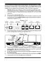
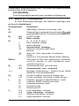
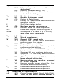
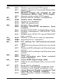
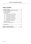
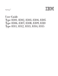
High Performance
V.90/K56Flex/V.34+/V.42bis
56K BPS
Plug & Play External
Voice/FAX/Data Modem
With Advanced
Speakerphone functions
User's Manual
Contents
Section One - Introduction ........................... 1
Section Two - Installation ............................. 1
Section Three - AT Command Set ............... 6
Section Four - S Registers ........................ 13
Section Five - Result Codes ...................... 15
Section Six - Troubleshooting .................... 15
Section Seven - Support and Service ......... 17
Appendix A - Specifications ..................... 17
Appendix B - Notices ................................ 18
SF-1156V/R21 V1.0
The information contained in this manual has
been validated at the time of this manual's production. The manufacturer reserves the right to make
any changes and improvements in the product
described in this manual at any time and without
notice. Consequently the manufacturer assumes
no liability for damages incurred directly or indirectly from errors, omissions or discrepancies
between the product and the manual.
All registered trademarks are the property of their
respective owners.
Copyright 1998 All rights reserved. No reproduction of this document in any form is permitted
without prior written authorization from the Manufacturer.
Section One - Introduction
This 56 Kbps* Plug and Play FAX/Voice/Data Speakerphone Modem connects your computer to all popular
high speed modems available today. The modem incorporates "V.90/K56Flex"(56Kbps) technology to provide
increased download speeds using regular telephone
lines. The modem incorporates Plug and Play for ease of
installation. It features speakerphone capabilities for
hands-free communication.
This manual describes the hardware installation procedures for your new modem. Additional information on
AT commands and S-registers is provided so that your
system can be customized for a particular operating
environment.
*Note:V.90/K56Flex is capable of downloading at 56Kbps.
However, current FCC regulations limit its speeds to
53Kbps.
Section Two - Installation
This section will provide step by step instructions on
how to install your new 56 Kbps Voice/FAX/Data modem.
Installation of this modem product is a two-step process
consisting of: 1) hardware installation and, 2) communication software installation and configuration.
2.1 Unpacking Your Modem
Be certain that you have all the items listed below. This
package contains:
¡EA modem
¡EA modem power supply
¡EA telephone cable
¡EA User's manual
¡ESoftware for the modem
¡ESoftware user's manual
2.2 Hardware Installation
Installation of this modem requires an available serial
port on your computer. This is either a 25-pin or 9-pin male
connector on the back of your computer. Consult the
computer's manual on this topic. You will also need a
properly configured serial cable. The recommended cable
for IBM Compatible PCs with a 25-pin serial port is an RS232 cable with all 25 pins configured Straight-through.
1
For computers with a 9-pin serial port, use an IBM AT type
(9-pin to 25-pin) RS-232 serial cable. For Macintosh Plus
or newer computers, use only a high speed RS-232 serial
cable that supports hardware flow control signals.
Note: Exercise caution when working with any ACpowered device. Always turn the power off when
connecting or disconnecting cables to or from the
device.
1. Turn your computer off.
2. Plug the male end of the RS-232 modem cable into the
connector marked RS-232C on the back of the modem
(refer to Figure 2-1).
Figure 2-1
Power
Switch
Power
RS-232C
Connector Connection
Audio
Jack
SPK
Line
Phone
Connection Connection
MIC
3. Plug the other end of the cable into the serial port on
your computer (refer to Figure 2-2).
Figure 2-2
PHONE
LINE
MIC
SPK
RS-232C
POWER
4. Turn the modem's power switch off. Plug the round
end of the power cord into the connector marked
POWER on the back of the modem.
5. Plug the transformer end of the power adapter into an
AC wall outlet.
6. Connect the telephone cable from the modem's LINE
“ c connector to the telephone wall jack.
2
7. Optionally, connect a telephone to the modem's PHONE
connector.
8. Turn the modem on.
9. Turn your computer on. Your modem is now installed.
If you are running Windows 95, continue to Section
2.3 for configuration information. Otherwise, proceed to
Section 2.4 for communication software installation.
2.3 Configuring in Windows 95
2.3.1
Windows 95 Release 4.00.950
When Windows 95 starts for the first time after card
installation, it detects the modem and displays the New
Hardware Found dialog box.
Under New Hardware Found, when asked to "Select which driver you want to install for your new
hardware,"click on "Driver from disk provided by hardware manufacturer. "Click OK."
The Install From Disk dialog box now instructs you
to "insert the manufacturer's installation disk into the drive
selected, and then click OK. "Insert the modem's driver
diskette into the disk drive and type A:\ (or B:\ if inserted
in drive B) in the "Copy manufacturer's files from:"box.
Click "OK."
Windows 95 may request its own installation disks or
CD-ROM for some files. Insert the Windows 95 disks or
CD-ROM as required. When all necessary files are
copied, the modem is configured. Proceed to Section
2.4.
2.3.2
Windows 95 Release 4.00.950 B
When Windows 95 starts for the first time after card
installation, it detects the modem and displays the Update
Device Driver Wizard.
Insert the driver disk into the disk drive and click
"Next." Windows will find the driver on the driver disk.
Click "Finish." Windows 95 may request its own installa3
tion disks or CD for some files. Insert the Windows 95
disks or CD as required.
Windows will now find a second device on the
modem. Make sure that the driver disk is still in the disk
drive and click "Next." Windows will find the second
driver. Click "Finish" to complete the installation.
When all necessary files are copied, the modem is
configured. Proceed to Section 2.4.
2.4 Software Installation and Configuration
You are now ready to install and configure the
communication software. Refer to your software manual
for installation procedures.
We suggest the following communication parameters
when you first use your data communication software.
Consult the software manual for information on using
these and other parameters/features.
115,200 bps; 8 data bits; no parity; 1 stop bit;
RTS/CTS flow control set to on;” initialization
string:AT&F.
We suggest that a "Generic Class 1" modem type
should be selected in your fax software, and a “Generic
Rockwell” modem type should be selected in your Voice
software.
Note that the COM port setting in your communication software must be the COM port that
connects the modem to the computer.
2.5 Using the Fax, Voice, and Speakerphone
Capabilities of the Modem
Your modem has built-in advanced FAX, Voice, and
Full Duplex Speakerphone functions. Please consult your
FAX/Voice/Speakerphone software manual about procedures on using these features.
Voice functions include recording and playback of
voice prompts (files). You may record or playback voice
with your modem by attaching a telephone to the RJ-11
jack marked "PHONE" or by attaching a microphone to the
MIC jack and a speaker to the SPK jack located on the back
of the modem bracket. Follow instructions in the FAX/
4
Voice/Speakerphone software on recording and playback of voice prompts.
2.6 Testing Your Modem After Installation
In order to test your modem you should be familiar with
your communication software. Load and set up your
communication software and enter into "Terminal mode."
Make sure that the COM Port and IRQ settings of the
software match the modem. Type AT on your terminal
screen and press ENTER. You may see AT,AATT or
nothing on the screen. In any case, the modem should
respond with an OK or 0. If it does not, please refer to
Section 6 for troubleshooting information.
2.7 Using Your Modem
The communication software included with your
modem product provides a user friendly interface to
access the voice and fax and data functions of your
modem. This software should be sufficient for all of
your communication needs. There may be times
when you need to access the modem manually via modem
commands. Read Section 3 for a summary description of
the modem command set before manually accessing the
modem. You may want to read the software manual first,
however, as the software may already provide a user
friendly method of accessing the functions you need (i.e.
dialing or answering calls).
2.8 Front Panel LEDs
The modem provides LED indicators on the front panel
to allow call progress monitoring. When the LEDs are lit
they indicate the following:
TST
HS
AA
CD
OH
RD
Flashing when the modem is in the test mode
or if an error is detected.
High speed -on when communicating at 2400
bps or above.
Auto-Answer On when auto answeris
enabled. Flash when ring is detected.
Carrier Detect The modem has detected a
carrier signal from the remote modem
Off Hook The modem has gone off hook in
preparation to dialing or answering a call
Receive Data Data is being sent to the
5
SD
TR
MR
computer from the modem
Send Data Data is being received by the
modem from the computer
Terminal Ready The modem is able to receive
commands.
Modem Ready The modem is turned on.
2.9 Where To Go From Here
You should familiarize yourself with the functions
available from the included software by reading its
manual. You will be accessing most, if not all, of the
modem's functions from this software. You may also use
any other commercially available communication software with the modem. Read Section 3 ONLY if you are
interested in accessing the modem manually, and not
through the included software. Section 4 and 5 contain
reference material, and can be skipped. If you have
difficulties getting your modem to work, read Section 6,
Troubleshooting to find answers to commonly asked
questions and problems.
Section Three - AT Command Set
3.1 Executing Commands
Commands are accepted by the modem while it is in
Command Mode. Your modem is automatically in Command Mode until you dial a number and establish a
connection. Commands may be sent to your modem from
a PC running communication software or any other
terminal devices.
Your modem is capable of data communication at rates of:
300, 1200, 2400, 4800, 9600, 14400, 19200, 28800,
38400, 57600, and 115200 bps. Make sure your COM port
baud rate settings in your communications software is set
to one of the above speeds.
3.2 Command Structure
All commands sent to the modem must begin with AT
and end with ENTER. All commands may be typed in
either upper or lower case, but not mixed. To make the
command line more readable, spaces may be inserted
between commands. If you omit a parameter from a
6
command that requires one, it is just like specifying a
parameter of 0. Example:
ATH [ENTER]
This command causes your modem to hang up.
3.3 Basic AT Commands
In the following listings, all default settings are
printed in bold text.
Command
Function
A
Manually answer incoming call.
A/
Repeat last command executed. Do not
precede A/ with AT or follow with ENTER.
B_
B0
B1
CCITT mode
Bell mode
L
P
T
W
,
@
!
;
0 - 9, A-D, # and *
last number redial
pulse dialing
touch-tone dialing
wait for second dial tone
pause
wait for five seconds of silence
flash
return to Command Mode after dialing
D_
DS=n
E_
Dial one of the four telephone numbers
(n=0-3) stored in the modem’s nonvolatile memory.
E0
E1
+++
Commands are not echoed
Commands are echoed
Escape Characters - Switch from Data
Mode to Command Mode
H_
H0
H1
Force modem on-hook (hang up)
Force modem off-hook (make busy)
I_
I0
I1
I2
I3
I4
Display product-identification code
Factory ROM checksum test
Internal memory test
Firmware ID
Reserved ID
L_
L0
L1
L2
L3
Low speaker volume
Low speaker volume
Medium speaker volume
High speaker volume
7
M_
M0
M1
M2
M3
Internal speaker off
Internal speaker on until carrier
detected
Internal speaker always on
Internal speaker on until carrier detected
and off while dialing
N_
N0
N1
Disable Autoscan mode
Enable Autoscan mode
O_
O0
O1
Return to Data Mode
Return to Data Mode and initiate an
equalizer retrain
P
Q_
Set Pulse dial as default
Q0
Q1
Modem sends responses
Modem does not send responses
Sr?
Read and display value in register r.
Sr=n
Set register r to value n (n = 0-255).
T
Set Tone Dial as default
V_
V0
V1
Numeric responses
Word responses
W_
W0
W1
Report DTE speed only
Report line speed, error correction
protocol, and DTE speed.
Report DCE speed only
W2
X_
X0
X1
X2
X3
X4
Y_
Y0
Y1
Z_
Z0
Z1
Hayes Smartmodem 300 compatible
responses/blind dialing.
Same as X0 plus all CONNECT responses/
blind dialing
Same as X1 plus dial tone detection
Same as X1 plus busy detection/blind
dialing
All responses and dial tone and
busy signal detection
Modem does not send or respond
to break signals
Modem sends break signal for four
seconds before disconnecting
Reset and retrieve active profile 0
Reset and retrieve active profile 1
3.4 Extended AT Commands
&C_
&C0
&C1
Force Carrier Detect Signal High (ON)
Turn on CD when remote carrier is
8
present
&D_
&D0
&D1
&D3
Modem ignores the DTR signal
Modem returns to Command Mode after
DTR toggle
Modem hangs up, returns to the
Command Mode after DTR toggle
Resets modem after DTR toggle
&F_
&F
Recall factory default configuration
&G_
&G0
&G1
&G2
Guard tone disabled
Guard tone disabled
1800 Hz guard tone
&K_
&K0
&K3
Disable flow control
Enable RTS/CTS hardware flow
control
Enable XON/XOFF software flow control
Enable transparent XON/XOFF flow
control
Enable both RTS/CTS and XON/XOFF
flow control
&D2
&K4
&K5
&K6
&L_
&L0
&M_
&M0 Asynchronous operation
&P_
&P0
&P1
&P2
&P3
Modem is set up for dial-up operation
US setting for off-hook-to-on-hook
ratio
UK and Hong Kong off-hook-to-on-hook
ratio
Same as &P0 setting but at 20 pulses per
minute
Same as &P1 setting but at 20 pulses per
minute
&R_
&R0
&R1
Reserved
CTS operates per flow control
requirements
&S_
&S0
&S1
Force DSR Signal High (ON)
DSR off in command mode, on in on-line
mode
&T_
&T0
&T1
&T3
&T4
Ends test in progress
Perform Local Analog Loopback Test
Perform Local Digital Loopback Test
Grant Remote Digital Loopback Test
request by remote modem
Deny Remote Digital Loopback Test
request
&T5
9
&T6
&T7
&T8
Perform a Remote Digital Loopback Test
Perform a Remote Digital Loopback Test
and Self-Test
Perform Local Analog Loopback Test
and Self-Test
&V
&V0
&V1
&W_
&W0 Stores the active profile as Profile 0
&W1 Stores the active profile as Profile 1
&Y_
&Y0
&Y1
Displays Active and Stored Profiles
Display Last Connection Statistics
Configuration Profile 0 active upon
Power on or reset
Configuration Profile 1 active upon Power
on or reset
&Zn=x
n=0-3 Store phone number x into non-volatile
RAM
%E_
%E0
%E1
Disable auto-retrain
Enable auto-retrain
+MS?
Displays the current Select Modulation
settings
+MS=?
Displays a list of supported Select
Modulation options
+MS=a,b,c,d.e,f
Select modulation where: a=0, 1, 2,
3, 9, 10, 11, 12, 56, 64, 69; b=0-1;
c=300-56000; d=300-56000; e=0-1;
and f=0-1. A, b, c, d, e, f default=12, 1,
300, 56000, 0, 0. Parameter "a" specifies
the modulation protocol desired where:
0=V.21, 1=V.22, 2=V.22bis, 3=V.23,
9=V.32, 10=V.32bis, 11=V.34,
12=V.90,K56Flex,V.34......,
56=K56Flex, V.90,V.34......, 64=Bell
103, and 69=Bell 212. Parameter "b"
specifies automode operations where:
0=automode disabled, 1= automode
enabled with V.8/V.32 Annex A.
Parameter "c" specifies the minimum
connection data rate (300-56000).
Parameter "d" specifies the maximum
connection rate (300-56000); Parameter
"e" specifies the codec type (0=£gLaw, and 1=A-Law). Parameter "f"
specifies "robbed bit" signaling
detection (0=detection disabled
10
1=detection enabled)
#CID=n n=0
n=1
n=2
Disable Caller ID
Enables Caller ID with formatting (date,
time, number, name)
Enables Caller ID without formatting
#CID?
Displays current Caller ID mode
#CID=?
Returns Caller ID capabilities of modem.
3.5 MNP/V.42/V.42bis Commands
%C_
%C0 Disable MNP Class 5 and V.42bis data
compression
%C1 Enable MNP Class 5 data compression
only
%C2 Enable V.42bis data compression only
%C3 Enable MNP Class 5 and V.42bis data
compression
&Q_
&Q0
&Q5
&Q6
Direct data link only (same as \N1)
V.42 data link with fallback options
Normal data link only (same as \N0)
\A_
\A0
\A1
64-character maximum MNP block size
128-character maximum MNP block
size
192-character maximum MNP block size
256-character maximum MNP block size
\A2
\A3
\Bn
Send a 1/10 second line break to the
modem, where n = 1 to 9. At normal
connect, the default is 3
\Kn
Set break control, where n= 0 to 2. The
effect of this command depends on the
modem operating condition. Default is
1.
\N_
\N0
\N1
\N2
\N3
\N4
\N5
Normal data-link only
Direct data-link only
V.42 or MNP data link only
V.42/MNP/Normal data link
V.42 data link only
MNP data link only
3.6 Fax Class 1 Commands
+FAE=n
+FCLASS=n
+FRH=n
+FRM=n
Data/Fax Auto Answer
Service Class
Receive data with HDLC framing
Receive data
11
+FRS=n
+FTH=n
+FTM=n
+FTS=n
Receive silence
Transmit data with HDLC framing
Transmit data
Stop transmission and wait
3.7 Fax Class 2 Commands
+FCLASS=n
+FAA=n
+FAXERR
+FBOR
+FBUF?
+FCFR
+FCLASS=
+FCON
+FCIG
+FCIG:
+FCR
+FCR=
+FCSI:
+FDCC=
+FDCS:
+FDCS=
+FDIS:
+FDIS=
+FDR
+FDT=
+FDTC:
+FET:
+FET=N
+FHNG
+FK
+FLID=
+FLPL
+FMDL?
+FMFR?
+FPHCTO
+FPOLL
+FPTS:
+FPTS=
+FREV?
+FSPT
+FTSI:
Services class.
Adaptive answer.
Fax error value.
Phase C data bit order.
Buffer size(reade only).
Indicate confirmation to receive.
Service class.
Facsimile connection response.
Set the polled station identification.
Report the polled station identification.
Capability to receive.
Capability to receive.
Report the called station ID.
DCE capabilities parameters.
Report current session.
Current session results.
Report remote capabilities.
Current sessions parameters.
Begin or continue phase C receive data.
Data transmission.
Report the polled station capabilities.
Post page message response.
Transmit page punctuation.
Call termination with status.
Session termination.
Local ID string.
Document for polling.
Identify model.
Identify manufacturer.
Phase C time out.
Indicates polling request.
Page transfer status.
Page transfer status.
Identify revision.
Enable polling.
Report the transmit station ID.
3.8 Voice Commands
#BDR
#CID
Select Baud Rate
Enable Caller ID detection and reporting
12
#CLS
#MDL?
#MFR?
#REV?
#TL
#VBQ?
#VBS
#VBT
#VCI?
#VLS
#VRA
#VRN
#VRX
#VSDB
#VSK
#VSP
#VSR
#VSS
#VTD
#VTM
#VTS
#VTX
format
Select Data, Fax or Voice/Audio
Identify Model
Identify Manufacturer
Identify Revision Level
Audio output transmit level
Query Buffer Size
Bits per sample (ADPCM or PCM)
Beep Tone Timer
Identify Compression Method
Voice line select
Ringback goes away timer
Ringback never came timer
Voice Receive Mode
Silence deletion tuner
Buffer skid setting
Silence detection period
Sampling rate selection
Silence deletion tuner
DTMF tone reporting capability
Enable timing mark placement
Generate tone signals
Voice transmit mode
Section Four - S Registers
Your modem has 41 registers, designated S0 through
S95. Table 4-1 shows the registers, their functions, and
their default values. Some registers can have their values
changed by commands. If you use a command to change
a register value, the command remains in effect until you
turn off or reset your modem. Your modem then reverts
to the operating characteristics specified in its nonvolatile memory. Refer to Section 3 for information on how
to use the AT commands to manipulate the S registers.
Table 4-1 S - Registers
Register
S0
S1
S2
S3
S4
S5
S6
S7
Function
Range/units Default
Auto-answer Ring
Ring counter
Escape code character
Carriage return character
Line feed character
Backspace character
Dial tone wait time
Remote carrier wait time
13
0-255 /rings
0-255 /rings
0-255 /ASCII
0-127 /ASCII
0-127 /ASCII
0-255 /ASCII
2-255 /seconds
1-255 /seconds
0
0
43
13
10
8
2
50
S8
S9
S10
S11
S12
S13
S14
S15
S16
S17
S18
S19-20
S21
S22
S23
S24
S25
S26
S27
S28
S29
S30
S31
S32
S33
S34-35
S36
S37
S38
S39
S40
S41
S42-45
S46
S47
S48
S49-81
S82
S83-85
S86
S87-S90
S91
S92
S95
Comma pause time
Carrier detect response time
Carrier loss time
Touch-tone dialing speed
Escape character guard time
Reserved
Echo, response, dialing,
originate/answer
Reserved
Modem tests
Reserved
Length of modem tests
Reserved
CTS, DTR, DCD, DSR and
long space disconnect
Speaker and response
Remote digital loopback
request, data rate, parity
Sleep mode timer
Data terminal ready delay
RTS to CTS delay interval
Asynchronous/Bell/CCITT
modes
Pulse dial, make/break ratio
Flash time
Disconnect timer
Autoscan, EC result code
XON character
XOFF character
Reserved
LAPM failure options
Reserved
Hang-up delay
Flow control options
MNP options, break types
block modes
Compression, retrain
Reserved
Data compression control
Reserved
V.42 negotiation options
Reserved
Break options
Reserved
Connection failure code
Reserved
Transmit attenuation
Fax attenuation
Extended result code
options
14
0-255 /seconds
1-255 /0.1 second
1-255 /0.1 second
50-255 /milliseconds
0-255 /0.02 second
2
6
14
95
50
Bit-mapped register
Bit-mapped register
0
0-255 /seconds
0
Bit-mapped register
Bit-mapped register
Bit-mapped register
0-255 seconds
0-255 /0.01 second
0-255 /0.01 second
Bit-mapped register
0
5
1
Bit-mapped register
0-255 /0.01second
0-255 /10 seconds
Bit-mapped register
0-255 /ASCII
0-255 /ASCII
17
19
Bit-mapped register
7
0-255 /seconds
Bit-mapped register
Bit-mapped register
20
3
104
Bit-mapped register
195
136 or 138
138
70
0
0, 7, or 128
7
3, 7, or 128
128
0-225
0-15/dBm
0-15/dBm
Bit-mapped register
10
10
0
Section Five - Result Codes
OK
0
RING
2
ERROR
4
NO DIALTONE
6
NO ANSWER
8
CONNECT 2400
10
CONNECT 9600
12
CONNECT 12000
14
CONNECT 16800
59
CONNECT 24000
62
CONNECT 28800
64
CONNECT 32000
165
CONNECT 36000
167
CONNECT 38400
17
CONNECT 42000
170
CONNECT 46000
172
CONNECT 50000
174
CONNECT 54000
176
CONNECT 57600
18
CONNECT 33600
84
CONNECT 1200TX/75RX 22
FAX
33
CARRIER 300
40
CARRIER 75/1200
45
CARRIER 2400
47
CARRIER 7200
49
CARRIER 12000
51
CARRIER 16800
53
CARRIER 21600
55
CARRIER 26400
57
CARRIER 32000
150
CARRIER 36000
152
CARRIER 40000
154
CARRIER 44000
156
CARRIER 48000
158
CARRIER 52000
160
CARRIER 56000
162
CARRIER 33600
79
COMPRESSION: V.42BIS 67
PROTOCOL: NONE
70
PROTOCOL: ALT
80
CONNECT
1
NO CARRIER
3
CONNECT 1200
5
BUSY
7
CONNECT 600
9
CONNECT 4800
11
CONNECT 7200
13
CONNECT 14400
15
CONNECT 21600
61
CONNECT 26400
63
CONNECT 19200
16
CONNECT 34000
166
CONNECT 38000
168
CONNECT 40000
169
CONNECT 44000
171
CONNECT 48000
173
CONNECT 52000
175
CONNECT 56000
177
CONNECT 31200
91
CONNECT 115200
19
CONNECT 75TX/1200RX
23
DATA
35
CARRIER 1200/75
44
CARRIER 1200
46
CARRIER 4800
48
CARRIER 9600
50
CARRIER 14400
52
CARRIER 19200
54
CARRIER 24000
56
CARRIER 28800
58
CARRIER 34000
151
CARRIER 38000
153
CARRIER 42000
155
CARRIER 46000
157
CARRIER 50000
159
CARRIER 54000
161
CARRIER 31200
78
COMPRESSION: CLASS 5 66
COMPRESSION: NONE
69
PROTOCOL: LAPM
77
+FCERROR
+F4
Section Six - Troubleshooting
This section describes some of the common problems you may encounter while using your modem. If you
can not resolve your difficulty after reading this chapter,
contact your dealer or vendor for assistance.
15
Modem does not respond to commands.
1. Make sure the communication software is configured
to "talk" to the modem on the correct COM port and IRQ
setting (same COM port and IRQ setting as the
modem). Your communication software must know
which address your modem is using in the system in
order to pass data to it. Similarly, IRQ settings must be
set correctly to receive data from the modem.
2. Make sure that your modem is initialized correctly.
Your modem may have been initialized to not display
responses. You may factory-reset the modem by
issuing AT&F and press ENTER. The factory default
allows the modem to display responses after a
command has been executed.
Modem does not dial.
1. Make sure the modem is connected to a working
phone line. Replace the modem with a working phone
to ensure that the phone line is working.
2. Make sure the phone line is connected to the jack
marked "LINE" Incorrect connection prevents the
modem from operating properly. Refer to Section 2.3
for modem connection instructions.
Modem dials but does not connect.
1. Make sure the IRQ setting is identical on both the
modem and the software. Modem and software must
be configured identically.
2. Make sure the phone line is working properly. Replace
the modem with a regular phone and dial the number.
If the line sounds noisy, you may have difficulty
connecting to the remote device.
Modem makes a connection but no data
appears on your screen.
1. Make sure the correct data format (data bits, stop bits,
and parity bits) and flow control (RTS/CTS) are being
used.
2. Make sure the correct terminal emulation mode is
being used (see communication software manual).
High pitch tone is heard whenever you answer
the phone.
1. Make sure Auto-Answer is turned off. Your modem
is factory configured to NOT auto-answer. Issue
AT&F to factory reset your modem.
16
Modem experiences errors while
communicating with a remote modem.
1. Make sure the DTE speed is the same as the modem
connection speed when in Direct Mode.
2. Make sure the remote system and your modem use the
same communication parameters (speed, parity, etc.).
3. Make sure RTS/CTS hardware flow control is enabled
and XON/XOFF software flow control is disabled in
the communication software.
4. Make sure the data speed is not faster than your
computer's capability. Most IBM compatibles are capable of 19,200 bps under DOS and Windows 3.X.
Operating at higher speeds under Windows requires
a 486 or faster CPU or Windows 95.
Modem experiences bursts of errors or
suddenly disconnects while communicating
with a remote modem.
1. Make sure Call Waiting is turned off.
2. Make sure the phone line does not exhibit excess
noise.
Modem exhibits poor voice record or
playback.
1. Make sure the correct modem type is selected in the
Voice/FAX software. Use “Generic Rockwell” or
similar selection.
Section Seven - Support and Service
In the unlikely event you experience difficulty in the
use of this product, we suggest you: (1) consult the
Troubleshooting section of this guide and (2) consult with
your dealer. To obtain service for this product, follow the
Return Merchandise Authorization Procedure as outlined
in the Warranty card.
Appendix A - Specifications
Communication Std. V.90, K56Flex, V.34+, V.34,
V.32bis, V.32, V.29, V.27ter,
V.22bis, V.23, V.22, V.21, V.17,
Bell212/103
Data Compression: V.42bis/MNP5
Error Correction: V.42/MNP2-4
17
Host Interface:
RS232C
FAX Group:
Group III Send/Receive Standard
FAX Command set: EIA/TIA-578 Service Class 1,
Class 2
Transmit level:
-11 dBm +/- 1 dB
Receiver Sensitivity:-39 dBm (V.34); -43 dBm (all other
protocols)
UART:
16550 compatible
Data format:
300-115200 bps
Power:
0.75 W
Temperature:
0 to 55 degrees C (Operating)
Caller ID:
Yes
PnP:
Revision 1.0a
Speakerphone:
Full-duplex with DSP echo
cancellation
Appendix B - Notices
FCC Compliance
This equipment complies with Part 68 of the FCC Rules. On
this equipment is a label that contains, among other
information, the FCC registration number and Ringer
Equivalence Number (REN) for this equipment. You must,
upon request, provide this information to your telephone
company.
If your telephone equipment causes harm to the telephone
network, the Telephone Company may discontinue your
service temporarily. If possible, they will notify in advance.
But, if advance notice is not practical, you will be notified
as soon as possible. You will be informed of your right to file
a complaint with the FCC.
Your telephone company may make changes in its facilities, equipment, operations, or procedures that could affect
proper operation of your equipment. If they do, you will be
notified in advance to give you an opportunity to maintain
uninterrupted telephone service.
The FCC prohibits this equipment to be connected to party
lines or coin-telephone service.
In the event that this equipment should fail to operate
properly, disconnect the equipment from the phone line to
determine if it is causing the problem. If the problem is with
the equipment, discontinue use and contact your dealer or
vendor.
The FCC also requires the transmitter of a FAX transmission
18
be properly identified (per FCC Rules Part 68, Sec. 68.381
(c) (3)).
FCC Class B Statement
This equipment has been tested and found to comply with
the limits for a Class B digital device, pursuant to Part 15
of the FCC Rules. These limits are designed to provide
reasonable protection against harmful interference in a
residential installation. This equipment generates, uses
and can radiate radio frequency energy, and if not installed
and used in accordance with the instructions, may cause
harmful interference to radio communications. However,
there is no guarantee that interference will not occur in a
particular installation. If this equipment does cause harmful
interference to radio or television reception, which can be
determined by turning the equipment off and on, the user
is encouraged to try to correct the interference by one or
more of the following measures:
•Reorient or relocate the receiving antenna
•Increase the separation between the equipment and the
receiver
•Connect the equipment into an outlet on a circuit
different from that to which the receiver is connected
•Consult the dealer or an experienced radio / TV technician for help
Notice: 1) Shielded cables, if any, must be used in order
to comply with the emission limits. 2) Any change or
modification not expressly approved by the Grantee of the
equipment authorization could void the user’s authority to
operate the equipment.
DOC Compliance Information
NOTICE: The Canadian Department of Communications
label identifies certified equipment. This certification
means that the equipment meets certain telecommunications network protective, operational and safety requirements. The Department does not guarantee the equipment
will operate to the user’s satisfaction.
Before installing this equipment, users ensure that it is
permissible to be connected to the facilities of the local
telecommunications company. The equipment must also
be installed using an acceptable method of connection.
The customer should be aware that compliance with the
above conditions may not prevent degradation of service
in some situations.
Repairs to certified equipment should be made by an
19
authorized Canadian maintenance facility designated by
the supplier. Any repairs or alterations made by the user to
this equipment, or equipment malfunctions, may give the
telecommunications company cause to request the user to
disconnect the equipment.
Users should ensure for their own protection that the
electrical ground connections of the power utility, telephone lines and internal metallic water pipe system, if
present, are connected together. This precaution may be
particularly important in rural areas.
Caution: Users should not attempt to make such connections themselves, but should contact the appropriate electric inspection authority, or electrician, as appropriate.
NOTICE: The Load Number (LN) assigned to each terminal
device denotes the percentage of the total load to be
connected to a telephone loop which is used by the device,
to prevent overloading. The termination on a loop may
consist of any combination of devices subject only to the
requirement that the sum of the Load Numbers of all the
devices does not exceed 100.
UL Notice
Caution: This internal modem adapter is to be installed in
UL Listed computers only, Always disconnect the modem
adapter from the telephone system during installation or
when the cover is removed from the computer.
20