1
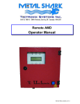
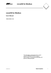
APPLICATION NOTE 048.051.IDM.011 12/19/02 Description: IDM240 - 5EI / IDM640 - 8EI Getting started with RS-485 serial communication Explains how to use the IDM240-5EI and IDM640-8EI drives with RS-485 serial communication, including how to setup the drives for RS-485 communication, recommended connections for an RS-485 network with one or more drives linked to a PC and how to use the IPM MotionStudio – V2.0.1.1 with an RS-485 network of drives. Steps to follow: 1. 2. 3. 4. 5. 6. 7. Setup the drives for RS-485 communication Mount on your PC an RS-485 interface board or an RS-232/RS-485 converter Install on your PC an RS-485 software driver Build the RS-485 network Setup IPM Motion Studio for communication via RS-485 with the drives Develop and test your motion application Set the drives in standalone operation Step 1. Setup the drives for RS-485 communication Perform the hardware settings presented in Appendix D to setup the IDM240-5EI/IDM640-8EI drive for RS485 communication. Step 2. Mount on your PC an RS-485 interface board or an RS-232 / RS-485 converter Usually, the standard PCs do not provide an RS-485 interface. In order to use the IPM Motion Studio to communicate with your drives via RS-485, you need to mount on your PC an RS-485 interface. This interface can be an add-in board or an RS-232 to RS485/RS-422 converter connectable to the standard serial ports of the PC. Technosoft provides, if needed, RS-232 to RS-485 converters as well as other accessories for RS485 networking. If you intend to use your own RS-232 to RS-485/RS-422 converter, please note that this should use the RTS line for transmission control, with the RTS signal active high (+5 to +12V) to enable the PC transmission and disable reception. These conditions are usually met by most of the RS-232 to RS-485/RS-422 converters. A typical example is the model IC-485SI from ATEN (www.aten-usa.com) that can be used either as RS-232 to RS-485 converter or as RS-232 to RS-422 converter. To use this model as an RS-232 to RS-485 converter, you need to: • set the switch DCE/DTE on position DCE • set the switch T-ON R-ON / T-RTS R-/RTS / T-RTS R-ON on position T-RTS R-/RTS • connect the RS-485 signal +A to converter inputs T+ and R+, the RS-485 signal -B to converter inputs T- and R- and the RS-485 ground to the converter shield1 Remark: the converter should free the RS-485 line immediately after the last stop bit is transmitted, without other delays. 1 If you use a non-isolated converter like model IC-485S from ATEN, connect the RS-485 ground to the PC serial connector ground Technosoft 2002 APN.011 - 1 APPLICATION NOTE 048.051.IDM.011 12/19/02 IDM240 - 5EI / IDM640 - 8EI Getting started with RS-485 serial communication Step 3. Install on your PC an RS-485 software driver In order to use an RS-232 to RS-485 converter with RTS control of the PC transmissions, you need to install on your PC an RS-485 serial driver. This driver should automatically activate the RTS line during the PC transmissions. If you don’t have an RS-485 driver, we recommend the following drivers: • for Windows 95 and Windows 98 - Integrity Instruments driver from: http://www.integrityusa.com/download.htm • for Windows NT and Windows 2000 – Sealevel driver from: http://www.sealevel.com/catalog/asyncsw.htm. For the Integrity Instruments driver, the installation instructions are presented in the readme.txt file included in the zip file to be downloaded. For the SeaCOM driver, the installation instructions are presented in Appendices G and H. Step 4. Build the RS-485 network Figure 1 shows how to do the network connections when working with one IDMx40-xEI drive linked via RS-485 with a PC equipped with an RS-232 to RS-485/RS-422 converter. J4 - RS-232 / RS-485 Connector IDMx40-xxI - RS-485 Connection - J4 120R 620R GND 620R 485B+5V 1 2 RS-232 Transceiver 3 DSP Controller 485A+ 232Tx 485Tx 5 6 9 232Rx +5V 485Rx RS-485 RS-485 Transceiver +3.3V 120R 485 / 232 OFF T+ T- R- R+ SW1 ON RS-232/RS-485 Adapter 3 RS-232 Figure 1. RS-485 connections: PC to J4 connector of IDMx40-xEI Technosoft 2002 APN.011 - 2 APPLICATION NOTE 048.051.IDM.011 12/19/02 IDM240 - 5EI / IDM640 - 8EI Getting started with RS-485 serial communication Figure 2 presents how to do the network connections when working with more drives and a PC equipped with an RS-232 to RS-485/RS-422 converter. +5V IDMx40 AXISID = 1 Node A 1K2 +485A 120R 5%, 0.25W -485B GND 1K2 +485A IDMx40 AXISID = 2 Node B PC Host Address = 255 RS-232/RS-485 Adapter -485B GND +485A Node N -485B GND +5V 1K2 +485A IDMx40 AXISID = 254 Node Z 120R 5%, 0.25W -485B GND 1K2 Figure 2. RS-485 connections: PC and multiple drives. If cable length is over 150 m, apply polarity bias circuits at both network ends as shown in this figure. If cable length is under 150m, you may apply a polarity bias circuit only at one network end, as shown in Figure 1 Technosoft 2002 APN.011 - 3 APPLICATION NOTE 048.051.IDM.011 12/19/02 IDM240 - 5EI / IDM640 - 8EI Getting started with RS-485 serial communication Step 5. Setup IPM Motion Studio for communication via RS-485 with the drives 1. Create in your IPM Motion Studio project an application for each drive. It is not necessary to perform also the setup and tuning for each drive. This operation may be done later using RS485 communication 2. Select command “Projects | Settings” and click the tab “General”. Set for each application an “Axis Number” equal with the drive address value (axis ID). The address is set from the drive’s address switch SW1 (see the table D.1 in appendix D). For example if you use 3 drives and you have set their axis ID as 1, 2 and 3, you should also have 3 applications in your IPM Motion Studio project with the “Axis Number” values: 1, 2 and 3. Close dialogue with OK 3. Power-on the drives 4. Perform the IPM Motion Studio software settings for RS-485 communication (see Appendix E) Step 6. Develop and test your motion application Once you have setup the RS-485 communication, you can choose one by one the drives to work with by selecting the application which has the “Axis Number” identical with the axis ID of the drive. Thus for each drive, you can perform the same operations you usually do with one drive connected via RS-232: setup and tune the drive for the motor and load used, develop and test the motion to be executed. Step 7. Set the drives in standalone operation By default, when you create a new application (either by adding one to an existent IPM Motion Studio project, or by starting a new project which automatically creates a first application), the TML (Technosoft Motion Language) program of this application, which includes all the drive settings and the motion to be performed, is compiled for and downloaded into the E2ROM memory of the drive. In order to set these drives for standalone operation, you need to perform the following steps: 1. Power Off the drive 2. Put the switch ‘Auto/Ext’ from SW1 DIP-Switch on position ON. This operation sets the drive in the AUTORUN mode, where after power on, the drive starts executing automatically the TML program from the E2ROM memory 3. Power On the drive Remark: After power on, the default baud rate of the Technosoft drives is 9600. If you set a different baud rate in IPM Motion Studio, each time you open IPM Motion Studio, it will try to detect the drives baud rate, then change them to the value you have chosen. The process is transparent for you as long as IPM Motion Studio is able to perform these operations successfully for all the drives. However if, with IPM Motion Studio open, you set the drives for standalone operation, you may temporary loose the communication if the IPM Motion Studio is set for a baud rate different from 9600 which is the drives value after reset. In order to restore it, you need to press the “Refresh Serial Settings” button or select the command “Tools | Refresh Serial Settings”. This command will start the automatic baud rate detection, followed by the baud rate change to the value you have chosen for IPM Motion Studio. Technosoft 2002 APN.011 - 4 APPLICATION NOTE 048.051.IDM.011 12/19/02 IDM240 - 5EI / IDM640 - 8EI Getting started with RS-485 serial communication Tips regarding standalone operation of the drives 1. How to change the baud rate of the drives set in standalone operation By default, the drives set in standalone operation start after power on with a baud rate of 9600. In the absence of the IPM Motion Studio this value remains unchanged. If your host uses a different baud rate, it is possible to program the drives to automatically change, after power on, their baud rate to match that of the host. You can do this by adding the instruction for baud rate change, at the beginning of your motion program, in the following way: 1. In Project window, click Motion, then select the first line 2. Click “MISC” (Miscellaneous) button from group “Assignment & data transfer”. At Serial Communication, select “Set SCI Baudrate to” and select the desired baud rate 3. Close dialogue with OK. Click button “Move Up” to set this instruction as the first one, in order to execute as soon as possible after power-on. Close Motion dialogue with OK 4. You need to recompile and download the program. This operation means: a. Select command “Build | Generate Code” b. Select command “Build | Rebuild All” c. Select command “View”. If on the menu items “Command Interpreter” is not checked, select it, else go to command “Windows” and select the “Command Interpreter” window to bring it in front. d. Type on the command interpreter prompter, the following commands i. TML>axisoff<Enter> ii. TML>end<Enter> e. Select command “Application | Download Program”. On the bottom line of the IPM Motion Studio you’ll see the progress of drive programming. Wait until the message: “Entry Point: 0x4000” occurs An alternate way is to get out the drives from the standalone operation (see below), then press the Run button which compiles, downloads and starts the new program, and if the test is successful, set back the drive in standalone mode (see Step 7). 5. Power off then power on the drive to activate the new program 2. How to reprogram the drives set in standalone operation In a more general way, you can change the TML motion program of the drives that are set in standalone operation without removing the drives from this mode. The procedure is: 1. Modify the motion program 2. Select commands “Build | Generate Code”, then “Build | Rebuild All” to recompile and link the program 3. Stop execution of the program running on the drive (started when the drive was powered on). For this operation you need to open the command interpreter and type on the prompter, the following commands TML>axisoff<Enter> // disable motor control TML>end<Enter> // stop program execution 4. Select command “Application | Download Program” to download the new program into the drive 5. Power off, then power on the drive to activate the new program Technosoft 2002 APN.011 - 5 APPLICATION NOTE 048.051.IDM.011 12/19/02 IDM240 - 5EI / IDM640 - 8EI Getting started with RS-485 serial communication 3. How to get out the drives from standalone operation If you want to stop the drive executing automatically after reset the program downloaded into the E2ROM memory, you need to get out the drive from standalone operation. Set the ‘Auto/Ext’ switch from SW1 DIP-Switch to Ext position. Warning: When the drives are set in standalone operation, do not use the IPM Motion Studio button “Run” to compile, download and test a new motion program. Use only the procedure presented in the above paragraph “How to reprogram the drives set in standalone operation”. If the “Run” button is used, you download the new program on the same memory locations from where the old program is executing. This operation may lead to a corrupted program in the drive E2ROM with unpredictable results. Appendix A. IDMx40-xEI hardware settings for RS-232 communication 1. 2. 3. 4. Power-Off the IDMx40-xEI drive Connect an RS232 serial cable between your PC and J4 connector of the IDMx40-xEI (9pin DB9). Use a 9-wire standard serial cable non-inverting (one-to-one) or do connections as in Figure A.1. Set on position OFF the switch ‘485/232’ from the SW1 DIP-Switch (see the figure D.1. in appendix D) Power-On the IDMx40-xEI drive J4 - RS-232 / RS-485 Connector IDMx40-xxI - RS-232 Connection - TxD RxD GND 1 2 232Tx 485Tx 5 6 3 RS-232 Transceiver 3 9 232Rx +5V 485Rx SHIELD RS-485 Transceiver RS-232 DSP Controller J4 +3.3V 485 / 232 OFF SW1 ON Figure A.1. RS-232 serial connections for IDMx40-xEI with J4 Technosoft 2002 APN.011 - 6 APPLICATION NOTE 048.051.IDM.011 12/19/02 IDM240 - 5EI / IDM640 - 8EI Getting started with RS-485 serial communication Appendix B. IPM Motion Studio software settings for RS-232 communication 1. 2. 3. 4. 5. 6. 7. Select command Tools | Options and click the tab “Serial port” Select from “Serial type” RS-232 (default) Select the desired baud rate from “Baud Rate”. Default value is 9600 Set the “Axis ID of the drive connected to PC” equal with the drive address. For the IDMx40-xEI drives, check the drive address. This is set after power on by reading the drive’s address switches. Set the “Axis ID of the drive connected to PC” at the same value Select from “COM Port Number” the serial port of your PC, where you have connected the serial cable. By default COM2 is selected Leave the other parameters on their default settings: Open COM Port Exclusive – not checked, Read interval timeout – 1000 ms, Timeout multiplier – 700 ms, Timeout constant – 400 ms, Wait after RUN – 2000 ms, Enable Idle Board Checking – not checked, Show firmware in status bar instead of product ID – not checked, Enable serial communication logging to the output window – not checked Press the OK button If the communication works properly, you’ll see displayed on the bottom line of the IPM Motion Studio the product ID of the drive (for example: “P051.001.E002.F000B”), which is read from the EEPROM memory of the drive. Remark: Instead of the product ID you may also see the message “Board Present”. This message occurs when the product ID is not recognized or is missing, being by mistake erased from the drive EEPROM memory. For this situation, Technosoft provides a specific tool, called IPMSN.exe (IPM Serial Number Editor), which allows you to restore the product ID. This tool is installed in the main folder of the IPM Motion Studio. Appendix C. RS-232 communication troubleshoots If the RS-232 communication does not operate properly, you’ll get an error message. 1. 2. If the error message is “Cannot open the serial port”, the serial port selected from “COM Port Number” is used by another device of your PC (mouse, modem, etc.). Click “Cancel”, select another serial port and try again If the error message is “Cannot synchronize computer and drive baud rates”, click “Work Offline”, then check: • • • Serial cable connections; Serial cable type. You need a standard male-female 9-wire non-inverting (one-to-one) cable. If your PC serial port is DB25, use also a standard 25-to-9 pin serial adapter; Select command “Project | Settings” and press “General” tab. Check if “Axis Number” of your active application is the same with your drive address and the value of the “Axis ID of the drive connected to PC”: Technosoft 2002 APN.011 - 7 APPLICATION NOTE 048.051.IDM.011 IDM240 - 5EI / IDM640 - 8EI 12/19/02 Getting started with RS-485 serial communication • For the IDMx40-xEI drives, check the drive address. This is set after power on by reading the drive’s address switches. Set the “Axis Number” and the “Axis ID of the drive connected to PC” at the same value with the drive address. Drive hardware settings for RS-232 communication (see Appendix A) After you fix the problem, press “Refresh Serial Settings” button to restore communication. 3. If the communication operates usually but gives communication errors from time to time, check the following: • • • If your PC has an earth connection If your drive is linked to earth Try to increase the “Read interval timeout”, “Timeout multiplier” and “Timeout constant” parameters. Note that these parameters are related to PC serial operation and usually the default values for these parameters do not need to be modified Appendix D. IDMx40-xEI hardware settings for RS-485 communication Power-Off the IDMx40-xEI drive Set on position ON the switch ‘485/232’ from SW1 DIP-Switch Configure the Axis ID of the drive using the switches (see table below). The drive address must be different for each drive of the network and also different from the axis ID of PC (which is set by default 255) FU / Norm 485 / 232 ID-Bit4 ID-Bit3 ID-Bit2 ID-Bit1 ID-Bit0 Auto / Ext 1. 2. 3. OFF ON Figure D.1. SW1 – DIP Switch Technosoft 2002 APN.011 - 8 APPLICATION NOTE 048.051.IDM.011 12/19/02 IDM240 - 5EI / IDM640 - 8EI Getting started with RS-485 serial communication Table D.1. Axis ID / Address configuration 3 ID – Bit4 OFF OFF OFF OFF OFF OFF OFF OFF OFF OFF OFF OFF OFF OFF OFF OFF ON ON ON ON ON ON ON ON ON ON ON ON ON ON ON ON DIP Switch position 4 5 6 ID – Bit3 ID – Bit2 ID – Bit1 OFF OFF OFF OFF OFF OFF OFF OFF ON OFF OFF ON OFF ON OFF OFF ON OFF OFF ON ON OFF ON ON ON OFF OFF ON OFF OFF ON OFF ON ON OFF ON ON ON OFF ON ON OFF ON ON ON ON ON ON OFF OFF OFF OFF OFF OFF OFF OFF ON OFF OFF ON OFF ON OFF OFF ON OFF OFF ON ON OFF ON ON ON OFF OFF ON OFF OFF ON OFF ON ON OFF ON ON ON OFF ON ON OFF ON ON ON ON ON ON 7 ID – Bit0 OFF ON OFF ON OFF ON OFF ON OFF ON OFF ON OFF ON OFF ON OFF ON OFF ON OFF ON OFF ON OFF ON OFF ON OFF ON OFF ON Axis ID 255 1 2 3 4 5 6 7 8 9 10 11 12 13 14 15 16 17 18 19 20 21 22 23 24 25 26 27 28 29 30 31 Note: Others Axis ID values (32 - 255) can be set by software with AXISID instruction. Technosoft 2002 APN.011 - 9 APPLICATION NOTE 048.051.IDM.011 12/19/02 IDM240 - 5EI / IDM640 - 8EI Getting started with RS-485 serial communication Appendix E. IPM Motion Studio software settings for RS-485 communication 1. 2. 3. 4. 5. 6. 7. Select command Tools | Options and click the tab “Serial port” Select from “Serial type” RS-485 Select the desired baud rate from “Baud Rate” Set the “Axis ID of the PC” different from any drive address. The easiest way is to leave it as 255 (default) and make sure that all the drives have a different address. Select from “COM Port Number” the serial port of your PC, where you have connected the serial cable. By default COM2 is selected Leave the other parameters on their default settings: Open COM Port Exclusive – not checked, Read interval timeout – 1000 ms, Timeout multiplier – 700 ms, Timeout constant – 400 ms, Wait after RUN – 2000 ms, Enable Idle Board Checking – not checked, Show firmware in status bar instead of product ID – not checked, Enable serial communication logging to the output window – not checked Press the OK button If the communication works properly, you’ll see displayed on the bottom line of the IPM Motion Studio the product ID of the drive (for example: “P051.001.E002.F000B”), which is read from the EEPROM memory of the drive. Select one by one all the applications to check that the communication works properly with all the drives. Remark: Instead of the product ID you may also see the messages “RS-485 Mode” or “Board Present”. First message is displayed after you have opened IPM Motion Studio, but before opening a project. In this stage, the software doesn’t know with which drive (axis ID) it should try to communicate. The message “Board Present” occurs when the product ID is not recognized or is missing, being by mistake erased from the drive EEPROM memory. For this situation, Technosoft provides a specific tool, called IPMSN.exe (IPM Serial Number Editor), which allows you to restore the product ID. This tool is installed in the main folder of the IPM Motion Studio WARNING On some PC configurations and operating systems, you may encounter communication problems in RS-485 mode when running your application. In such cases try to reduce the communication speed progressively, starting with 115200 (use the ‘Tools |Options’ menu). Technosoft 2002 APN.011 - 10 APPLICATION NOTE 048.051.IDM.011 12/19/02 IDM240 - 5EI / IDM640 - 8EI Getting started with RS-485 serial communication Appendix F. RS-485 communication troubleshoots If the communication does not operate properly, you’ll get an error message. 1. 2. If the error message is “Cannot open the serial port”, the serial port selected from “COM Port Number” is used by another device of your PC. Click “Cancel”, select the PC serial port used for RS-485 operation and try again If the error message is “Cannot synchronize computer and drive baud rates” click “Work Offline”, then check: • • • • 3. RS-485 cable connections, presence of the 120 ohms terminal resistors at the two ends of the network and the presence of the bias circuit(s) to keep the line level in idle mode. If you use an RS-232/RS-485 converter with automatic control of transmission, check the specifications. Usually these devices free the RS-485 lines when a transmission ends, only after a time equivalent with transmission of another byte. You can’t use these devices, as the Technosoft drives respond to a data request faster. For correct operation you should use a device that frees the RS-485 lines immediately after the last stop bit transmitted. Select command “Project | Settings” and press “General” tab. Check if the “Axis Number” for all the applications associated with the drives from the network is correctly set. The “Axis Number” values should be the same as those programmed in the drives. Each drive must have a different axis number e.g. address. No drive can have the same address value as that set as axis ID of PC. Drive settings for RS-485 communication (see Appendix D). If the communication operates usually but gives communication errors from time to time, check the following: • • Check the network ground connection. This link is mandatory if the drives don’t have the same ground Try to increase the “Read interval timeout”, “Timeout multiplier” and “Timeout constant” parameters. Note that these parameters are related to PC serial operation and usually the default values for these parameters do not need to be modified Technosoft 2002 APN.011 - 11 APPLICATION NOTE 048.051.IDM.011 12/19/02 IDM240 - 5EI / IDM640 - 8EI Getting started with RS-485 serial communication Appendix G. RS-485 driver installation on Windows 2000 1. 2. 3. 4. 5. 6. 7. 8. 9. 10. 11. 12. 13. Download from http://www.sealevel.com/catalog/asyncsw.htm the SeaCOM Windows driver package and install it On your Windows 2000 system, click on the “Start” button from the task bar and choose “Setting | Control Panel” Double-click on the “System” icon and select the tab “Hardware” Press the “Device Manager” button At “Ports”, select Communication Port (COM1) if you want to communicate on COM1 or select Communication Port (COM2) if you want to communicate on COM2, then select “Action | Properties” command Select the tab “Driver”, press the “Update Driver” button and then the “Next” button Select “Display a list of the known drivers for this device so than I can choose a specific driver” radio button and press “Next” button Select “Show all hardware of this device class” radio button In the “Manufacturers” list, select the “Sealevel System, Inc.”, and in the “Models” list select “COMM+2/EX: 2 Port RS-232/422/485 (Port1)”. Press the “Next” button Respond “Yes” to the question “Do you want to continue installing this driver”? Press Next button, and then the Finish button In the Control Panel double-click on the “System” icon, select the tab “Hardware” and press the “Device Manager” button At “Ports”, select as Communication Port (COMx) the same as that selected at step 5., then select the command “Action | Properties”. Select the tab “Advanced” and at “RS-422/485 Control Options”, check “Auto RTS RS-485” Appendix H. RS-485 driver installation on Windows NT 1. 2. 3. 4. Download from http://www.sealevel.com/catalog/asyncsw.htm the SeaCOM Windows driver package and install it On your Windows NT system, click on the “Start” button from the task bar and choose “Setting | Control Panel” Double-click on the “Advanced Ports” icon and select the tab “Advanced” Select the COM port and at “RS-485 Options” check “Auto RTS-485” Technosoft 2002 APN.011 - 12