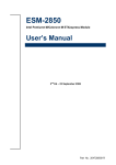
1
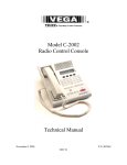
Hardware Technical Specification 5 Chapter Hardware Specifications You can enjoy and utilize the Z93E series Notebook more effectively with a better comprehension of detailed hardware specifications of the notebook. T his chapter lists the detailed specifications of the notebook’s main system and modules. Please refer to this section when you need to find out specific technical data about the notebook. This chapter contains the following information: System Specifications Chipset Specifications Key Parts List System Resource Module Specification 5-1 Hardware Technical Specification 1. MARKETING SPECIFICATION Processor & Sockets BIOS Chipset Main Memory Display Graphics & Video Module CRT Display Modes PC Card Slot Multi-Card Reader Hard Disk Drive Modem/FAX & LAN Optical Storage Device Wireless LAN & Bluetooth IrDA On-screenDisplay LED Status Indicator Mobile Intel® Pentium®- M & Intel Celeron M μPGA Package with Socket-478 0.13μ/0.09μ Processor Intel Pentium-M, 533 MHz FSB, 2MB L2 Cache, up to 780 processor, 2.13GHz Dothan Celeron M, 400MHz FSB, 1MB L2 Cache, up to 390 processor, 1.7GHz AMI BIOS code 4MB Flash EPROM PMU, Plug & Play Intel 915GM + ICH6M Two SO-DIMM socket for expansion up to 2048MB DDR 15.4” active matrix color TFT 15.4” WXGA; 15.4”WSXGA+ Intel 915GM+ ICH6M VGA 640 x 480, 256/32K/64K/16.7M colors SVGA 800 x 600 256/32K/64K/16.7M colors XGA 1024 x 768 256/32K/64K/16.7M colors SXGA 1280 x 1024 256/32K/64K/16.7M colors UXGA 1600x1200 256/32K/64K/16.7M colors PCMCIA 2.1 compliant One Type II Non-ZV port One built-in card reader support MMC/ SD Memory Stick/ MS Pro xD (we won’t claim xD support to enduser) 2.5" 9.5 mm IDE HDD with Ultra DMA100 supported 40 /60 / 80GB; support 4200/ 5400 RPM Fixed type, easy for BTO 10/100 BaseT LAN on board Azalia MDC Worldwide regulation, CTR21, JATE, FCC,DGT,A-Tick, 中國入網許可 (Regulation in China).etc passed (TW/PRC/EU/US) 5.25” 12.7mm 8X/ 24X (max.) DVD combo drive 8X DVD-Dual Fixed Type, 2-screw design for BTO Built-in WLAN antenna MiniPCI options of Intel Wireless Pro module supports Calexico 2(BTO option), 802.11 a/b/g compliant 11Mb/54Mb data transfer rate USB option for bluetooth SIR-115.2Kbps supported Brightness Display selection LCD/Ext. Monitor//TV-out LCD on/off AC adapter plug in/ Battery in use Volume On/Off Volume Up/Down Power4 Gear indicator Power-on/Suspend Bat. Charging/full Storage device access Cap. Lock Scroll Lock Num Lock E-mail in box 5-2 Hardware Technical Specification Keyboard Audio Interface Power Management Battery Pack& Life AC adapter Pointing Device Thermal Solution Support OS Security Dimensions Weight LED Status Indicator Microsoft MDA2003 requirement Macrovision Support Wireless indicator 19 mm full size 88key with MS-Windows function keys 2.5mm travel Built-in Azalia compliant audio chip, with 3D effect & full duplex Built-in stereo speakers. PortBar III 68-pin Connector One Headphone-out jack / SPDIF One Microphone-in jack, fixed. One Lin-in Jack One VGA port/Mini D-sub 15-pin for external DDC monitor One RJ11 Modem jack for phone line One RJ45 LAN Jack for LAN insert 3 USB 2.0 ports One IEEE 1394 port One TV-out Full feature ACPI power management, supports Stand-by, Suspend to Disk, and Suspend to RAM MDP 2003 compatible ASUS P4 Gear+ support 8 cells & 4cells, 2400mAh, 65Whrs Smart battery, charging time, 4hrs/2.5hrs (System On/ Off) to 95%. Output: 19V DC, 3.42A, 65W Input: 100~240V AC, 50/60Hz universal Built-in Touch pad pointing device 2 click buttons. ADTD (Developed by Asus) to handle 27W CPU thermal envelope. Keep discrete Gfx solution, GPU+ memory total 15W. Windows XP ,XP SPII Driver support XP Pre-OS Authentication by programmable key code BIOS Booting User Password Protection HDD User Password Protection and Security Lock Kensington Lock hole provided 369 x269x 34.8mm (W x D x H, typical) 2.8 kg (w/ 15.4” WLCD, 9.5mm HDD, 12.7” ODD and 4 cells Li-Ion battery pack) 3.0kg (<3.1kg) (w/ 15.4”W LCD, 9.5mm HDD, 12.7” ODD, and 8 cells Li-Ion battery pack) Power-on/Suspend Bat. Charging/full Storage device access Cap. Lock Scroll Lock Num Lock E-mail in box Wireless indicator Boot up within 40 sec Resume from S4 within 25 sec Resume from S3 within 5 sec Meet Macrovision Requirement for DVD-ROM model Meet Macrovision 525p requirement Factory Option CMOS Camera 1.3Million pixels CMOS Camera (Factory option) 5-3 Hardware Technical Specification Accessory Option PortBar III (option) Feature One 100/10 MHz RJ-45 LAN port One EPP/ECP Parallel port/D-sub 25-pin Four USB 2.0 ports One VGA port / D-sub 15-pin for external monitor 65W DC-in jacks and power supply to main unit through a cable interface Dimension: 200 x 160 x 37mm (max) Additional Spec S/W Utility Regulation Windows Certification Keyboard Language Asus Winflash for BIOS and Driver live Update Power4Gear: Pre-defined power saving theme HotKey: support instant key function defined Asus PC Probe ASUSDVD 2000 XP/Cyberlink PowerDVD (w/ DVD model) w/ latest qualified version Asus Screen Saver Asus Active Update Shipment bundle S/W: Trend PC-Cillin® 2004 Adobe Acrobat Reader 5.1 Nero v6.0 lite (w/ combo, DVD-RW SKU) EMI: USA(FCC-B), JAP(VCCI-B), BSMI, CCC Safety: CE, CB, TUV, cUL, CCC, Modem: Universal PPT including US(FCC-B), TWN(DGT), PRC (FCC68), JPN(JATE), EURO(CTR21) Compatibility: HCT V11.1a (Window XP ) Language: US Int’l, JAP, TWN Supported OS: Windows XP, MCE US, JAP, TWN before M/P France, GR CR,DN,CZ, IT, BL, NW, PO, SF, SP, SW, SC, FR, JP, RU ,UK Spain, AR, TU, Brazil when M/P PortBar III Interface Support Model Dimension Windows Certification One 100/10 MHz RJ-45 LAN port One EPP/ECP Parallel port/D-sub 25-pin 4 USB 2.0 ports One VGA port / D-sub 15-pin for external monitor Separately 65W DC-in jack and Power Supply to main unit through a cable interface NB S1N/M2N/M3N model 200 x 160 x 37mm(max.) Compatibility: HCT V10.0 (Window XP and ME), Supported OS: Windows XP/ME/2K/98SE, Additional Spec Regulation EMI: USA(FCC-B), TWN(檢磁), CCIB Safety: CE, CB, TUV, cUL, CCIB, Table 1.0.0 Marketing Specification List 5-4 Hardware Technical Specification 2. CHIPSET LIST Chipset Description HW ACPI/PC99 CPU Intel Pentium M & Celeron M (Dothan) Not required SRAM (L2 Cache) 2Mbyte (Pentium M), 512Kbyte (Celeron M) Not required NORTH BRIDGE Intel 915GM YES Intel ICH6-M Intel ICH6-M YES MEMORY DDR SDRAM Not required BIOS ROM SUPER I/O SST 49LF004B (4Mbit) ITE IT8705F Not required SOUTH BRIDGE SpeedStep Controller YES YES YES PCI-Cardbus / IEEE1394 /SD Card /Memory Stick /XD Controller AUDIO Azalia CODEC software Audio AUDIO AMPLIFIER TI TPA0212 ; TI TPA0211 KB CONTROLLER PIC (uP) MITSUBISHI M38857 PIC16C54C Not required IrDA VISHAY TFDU4100-TR3 Not required SUPER I/O ITE8705F YES LAN REALTEK RTL8100CL YES MODEM CLOCK Generator CONEXANT MDC Modem (HDA) ICS954213 YES RICOH R5C841 YES Not required YES YES Table 2.0.0 Chipset List 2.1. CPU Processor Type: Intel Pentium M Processor Frequency: 400 MHz FSB: 1.4 ~ 2.1 GHz 533 MHz FSB: 1.6 ~ 2.26 GHz Construction Method: 478 pin Micro-FCPGA Package Supply Voltage: 0.988 ~ 1.356 V Function Features: Support Intel Architecture with Dynamic Execution On-die, primary 32-KB instruction cache and 32-KB write-back data On-die, 2MB second level cache with Advanced Transfer Cache Architecture Data Pre-fetch Logic Streaming SIMD Extension 2 (SEE2) 400 MHz & 533 MHz, Source-Synchronous FSB Advanced Power Management features including Enhanced Intel SpeedStep technology 5-5 Hardware Technical Specification 2.2. NORTH BRIDGE Function Features: The GMCH provides high-performance, integrated graphics and manages the flow of information. System Memory Interface Support DDR & DDRII PCI Express Based Graphics (discrete graphics devices) Integrated Display Interface support Analog CRT DAC interface Digital LVDS interface support Timings must match for both display SSC must be disabled for LVDS port and CRT DAC single pipe simultaneous display mode Panel Fitting. Panning, and Center mode supported Spread spectrum clocking (SSC) supported Panel Power Sequencing support Integrated PWM interface for LCD Backlight Inverter Control Analog TV-Out Interface support Integrated TV-out device supported on Display pipe A and pipe B Multiplexed Output interface Macro-vision support Over-scan Scaling Support Serial Digital Video Output (SDVO) support Internal Graphics Features DVMT 3.0 support Intel Dual-Frequency Graphics Technology Intel Smart 2D Display Technology Asynchronous Display core and Render core clocks supported Dual Independent display pipes 32 bit Hardware cursor supported 2D graphics engine High Quality 3D Setup and Render Engine High Quality Texture Engine 3D Graphics Rendering Enchantments Video DVD/ PC-VCR support Video Overlay Power Management Enhanced Cx state support using GMCH HCPUSLP# Direct Media Interface (DMI) Vendor: Parts Number: Package: INTEL NQ82915GM 1257-ball Micro-FCBGA (40x37.5 mm) 5-6 Hardware Technical Specification 2.3. SOUTH BRIDGE Function Features: Direct Media Interface 10 Gb/s each direction, full duplex Transparent to software PCI Express 4 PCI Express root ports Fully PCI Express 1.0a compliant Cab be statically configured as 4x1, or 1x4 Two virtual channel support for full isochronous data transfers Support for full 2.5 Gb/s bandwidth in each direction per x1 lane Module based Hot-Plug supported PCI Bus Interface Support PCI Rev 2.3 Specification at 33 MHz Seven available PCI REQ/GNT pairs Support for 64-bit addressing on PCI using DAC protocol Integrated Serial ATA Host Controller Two ports Data transfer rates up to 1.5 Gb/s Integrated AHCI controller Integrate IDE Controller Independent timing of up to two drives Ultra ATA/100/66/33, BMIDE and PIO modes Tri-state modes to enable swap bay Intel High Definition Audio Interface PCI Express endpoint Independent Bus Master logic for eight general purpose streams Support three external Codecs Supports variable length stream slots Supports multi-channel, 32-bit sample depth 192 KHz sample rate output Provides mic array support Supports memory-based command/response transport Allows for non-48 KHz sampling output Support for ACPI Device States AC-Link for Audio and Telephony CODECs Support for three AC ’97 2.3 codecs Independent bus master logic for 8 channels Support for up to six channels of PCM audio output Supports wake-up events USB2.0 Includes four UHCI Host Controllers, supporting eight external ports Includes one EHCI Host Controller that supports all eight ports Includes one USB 2.0 High-speed Debug Port Supports wake-up from sleeping states S1-S5 Supports legacy Keyboard/Mouse software 5-7 Hardware Technical Specification Integrated LAN Controller Integrated ASF Management Controller WfM 2.0 and IEEE 802.3 Compliant LAN Connect Interface (LCI) 10/100 Mb/s Ethernet Support Power Management Logic ACPI 2.0 compliant ACPI-defined power states ACPI Power Management Timer Support “Intel SpeedStep technology” processor power control and “Deeper Sleep” power state PCI CLKRUN# and PME# support SMI# generation All registers readable/restorable for proper resume from 0V suspend states Support for APM-based legacy power management for non-ACPI Mobile implementations External Glue Integration Integrated Pull-up, Pull-down and Series Termination resistors on IDE, Processor I/F Integrated Pull-down and Series resistors on USB Enhanced DMA Controller Two cascaded 8237 DMA controllers Supports LPC DMA Vendor: Parts Number: Package: INTEL FW82801FBM 609-ball BGA (31x31 mm) 2.4. DRAM MEMORY 2.4.1. EXPANSION MEMORY Number of Sockets: Bus: Refresh Rate: Supply Voltage: Functional Features: Two 200 pin DDR SO-DIMM sockets 64-bit data path 8K refresh cycles/ 64ms 2.5V Double-Data-Rate architecture, 2 data transfers per clock cycle Bi-directional data strobe (DQS) Differential clock inputs DLL aligns DQ and DQS transition with CK transition Auto refresh and self refresh Programmable Mode Register Hardware Features: Easy removable and exchangeable for user Only support 333 MHz DDR SO-DIMM 5-8 Hardware Technical Specification 2.5. BIOS ROM ROM Type: Package: Supply voltage: Erase/program: Serviceability: 4Mbit CMOS Flash Memory PLCC 32-Lead 3.3V 100,000 erase/program cycles minimum End user refreshable design (software re-flash) 2.6. CARDBUS/IEEE 1394/SD/MS CONTROLLER Function Features PC98/99/2001 Compliant PC2001 Design Guide compliant (Subsystem ID, Subsystem Vendor ID) Compliant with ACPI and PCI Bus Power Management 1.1 Supports Global Reset Low Power Consumption Low operating power consumption due to the iprovement of Power management Software Suspend mode compliant with ACPI Hardware Suspend CLKRUN#, CCLKRUN# support The core logic – powered at 1.8V/2.5V, the others – powered at 3.3V PCI-CardBus/1394 Bridge/SD Card/Memory Stick/xD Picture Card/Express Card Interface slot PC Card 2 ports of IEEE 1394 MDIOxx pins shared by SD card, Memory Stick and xD Picture Card ¾ Providing Ricoh’s proprietary driver for Memory Stick and xD Picture Card/Express Card Express Card (USB Interface Type) supported by the PC Card passive adapter PCI Bus Interface Compliant with PCI Local Bus Specification 2.3 The maximum frequency 33 MHz PCI Master/Target protocol support Separated PCI configuration space per each function 3.3V interface (5V tolerant) CardBus PC Card Bridge Compliant with PC Card Standard Release 8.0 Specification The maximum frequency 33 MHz Supports CardBus Master/Target protocol Supports Memory Write Posting/ Read Pre-fetching Transfer transactions ¾ All memory read/write transaction (bi-direction) ¾ ¾ I/O read/write transaction (bi-direction) Configuration read/write transaction (PCI→Card) ¾ 2 programmable memory windows 5-9 Hardware Technical Specification ¾ 2 programmable I/O windows PC Card-16 Bridge Compliant with PC Card Standard Release 8.1 16-bit Specification 5 programmable memory windows 2 programmable I/O windows Compliant with i82365SL compatible register set/ExCA Supports Legacy 16-bit mode (3E0, 3E2 I/O ports) IEEE 1394 Interface Compliant with IEEE 1394-1995 Standard Specification and IEEE 13941-2000 Standard Specification Compliant with 1394OHCI Release 1.1/1.0 Standard Specification Supports Cycle Master Provides the Asynchronous receive/transmit FIFO and isochronous receive/transmit FIFO Supports Self-ID, physical DMA Data transmission rate of 100, 200 and 400 Mbps 2 ports of 1394 Cable interface 24.576 MHz crystal oscillator and Internal 393.216 MHz PLL Supports cable power monitoring (CPS) Set Initial values of Power Class and CMC by PCI Configuration registers Small Card Interface SD Memory Card ¾ Compliant with SD memory Card Specification Version 1.01 ¾ Compliant with SD Input/Output (SDIO) Card Specification Version 1.0 ¾ Compliant with SD Host Controller Standard Specification Version 1.0 Memory Stick ¾ Compliant with Memory Stick Standard Format Specification Version 1.4 ¾ Compliant with Memory Stick PRO Format Specification Version 1.00 xD Picture Card ¾ Compliant with xD Picture Card Specification Version 1.00 ¾ Compliant with xD Picture Card Host Guideline Version 1.00 ¾ Backward compatible with the Smart Media Express Card Interface Compliant with EXPRESS CARD STANDARD Draft Release 1.0 Pass USB signals from a USB-HOST to a Card Slot System Interrupt Supports INTA#, INTB#, INTC# and INTD# for PC system interrupt (Each unit is programmable) IRQx support for ISA system interrupt (Non shared IRQx pins: PC Card only) 5-10 Hardware Technical Specification Supports Serialized IRQ Supports Remote Wake Up by CSTSCHG Support an internal regulator to convert from 3.3V power to 2.5V power for core logic Supports Zoomed Video Port Supports PC Card LED, 1394 LED, SD LED, Memory Stick LED and xD Picture Card LED Vendor: Parts Number: Package: RICOH R5C841 208-ball CSP (16 x 16 mm, pitch = 0.8 mm) 2.7. EMBEDDED/KEYBOARD CONTROLLER Function Features Basic Machine-Language Instructions: 71 Minimum Instruction Execution time: 0.5 µs Memory Size ROM 32K bytes RAM 1024 bytes Vendor: Parts Number: Package: Programmable Input/Output Ports: 72 Software pull-up Transistors: 8 Interrupts: 22 sources, 16 vectors Timers: 8-bit x 4 Watchdog Timer: 16-bit x 1 PWM Output: 14-bit x 2 Serial I/O: 8-bit x 1 Multi-master I2C Bus Interface: 1 channel LPC Interface: 2 decordl Serialized IRQ: 3 factor A-D Converter: 10-bit x 8 channels D-A Converter: 8-bit x 2 channels Comparator Circuit: 8 channels Clock Generating Circuit: Built-in 2 circuits Power Source Voltage: 3.0 to 3.6 V MITSUBISHI ELECTRIC M38857M8-A02HP 80P6Q-A (14 x 14 mm) 5-11 Hardware Technical Specification 2.8. ETHERNET Function Features Integrated Fast Ethernet MAC, Physical chip, and transceiver in one chip 10 Mbps and 100 Mbps operation Supports 10 Mbps and 100 Mbps NWay auto-negotiation PCI Local bus single-chip Fast Ethernet controller Complies with PCI Revision 2.2 Supports PCI Clock 16.75 MHz – 40 MHz Supports PCI target fast back-to-back transaction Provides PCI bus master data transfers and PCI memory space or I/O space mapped data transfers of the RTL8100’s operational registers Support PCI VPD (Vital Product Data) Supports ACPI, PCI power management Supports 25 MHz crystal or 25 MHz OSC as the internal clock source. Complies with the PC99/PC2001 standard Supports Wake-On-LAN and remote wake-up Supports 4 Wake-On-LAN (WOL) signals (active high, active low, positive pulse, and negative pulse) Supports auxiliary power-on internal reset, to be ready for remote wake-up when main power remains off Support auxiliary power auto-detect, and sets the related capability of power management registers in PCI configuration space Includes programmable PCI burst size and early Tx/Rx threshold Support a 32-bit general-purpose timer, with the external PCI clock as clock source, for generating timer-interrupts Contains two (2Kbyte) independent receive and transmit FIFOs Advanced power saving mode when LAN and wakeup function are not used Uses 93C46 (64x16-bit EEPROM) to store resource configuration, ID parameter, and VPD data Supports LED pins for various network activity indications Support loopback capability Half/Full duplex capability Supports Full Duplex Flow Control 2.5/3.3V power supply with 5V tolerant I/Os Vendor: Parts Number: Package: REALTEK RTL8100CL 128-pin LQFP (16 x 22 mm) 5-12 Hardware Technical Specification 2.9. SUPER I/O Function Features: Vendor: Parts Number: Package: 2.10. Full ACPI 1.0 and PC98/99 compliant Support 10 IRQ channel options Integrated PC/AT Floppy Disk Controller Support 5.25”/3.5”/2.5” FDD Support 3-mode FDD Integrated Serial Port RS-232C Controller Integrated Infrared Controller Support IrDA 1.0 Integrated Parallel Port Controller Support Standard, bi-directional, ECP, EPP mode Support 2 general purpose pins for game port control Support voltage 5V ITE (INTEGRATED TECHNOLOGY EXPRESS ITE8705F 128-pin PQFP AUDIO CODEC HIGHT DEFINITION AUDIO (HDA) Function Features: High performance DACs with 95dB S/N ratio ADCs with S/N ratio greater than 85 dB Meets performance requirements for audio on PC2001 systems 8 DAC channels support 16/20/24-bit PCM format for 7.1 audio solution 3 stereo ADCs support 16/20-bit PCM format, two for microphone array, one for legacy mixer recording Supports 44.1K/48K/96K/192K Hz DAC sample rate All ADCs support 44.1K/48K/9K sample rate Applicable for 4-channel/192KHz and 6-channel/96KHz DVD-Audio solutions Up to four channels of microphone input are supported for AEC/BF application High-quality differential CD input Supports Power Off CD function Supports external PCBEEP input and built-in BEEP generator PCBEEP Pass-Through when link is in RESET state Software selectable 2.5V/3.75V VREFOUT Six VREFOUTs are supported Two GPI jack detection pins 16/20/24-bit S/PDIF-OUT supports 44.1K/48K/96KHz sample rate 5-13 Hardware Technical Specification 16/20/24-bit S/PDIF-IN supports 44.1K/48K/96KHz sample rate Optional EAPD supported Power management and enhanced power saving features Compatible with AC’97 Reserve analog mixer architecture for backward compatibility with AC ‘97 -64dB ~ +30dB with 1dB resolution of mixer gain to achieve finer volume control Impedance sensing capability for each re-tasking jack All analog jacks are stereo input and output re-tasking for analog plug & play Built-in headphone amplifier for each re-tasking jack Support external volume knob control Supports 2 GPIOs Hardware de-scrambling for DVD-Audio Content protection Meets Microsoft WHQL/WLP 2.0 audio requirements EAX 1.0 & 2.0 compatible Direct Sound 3D compatible A3D Compatible I3DL2 compatible HRTF 3D Positional Audio Emulation of 26 sound environments to enhance gaming experience 10 Software Equalizer Bands Voice Cancellation and Key Shifting in Karaoke mode Realtek Media Player Enhanced Configuration Panel and device sensing wizard to improve user experience Microphone Acoustic Echo Cancellation (AEC) and Beam Forming (BF) technology for voice application Mono/Stereo Microphone noise suppression Vendor: Parts Number: Package: REALTEK ALC880 48-pin LQFP (9 x 9 mm) 5-14 Hardware Technical Specification 2.11. AUDIO AMPLIFER Function Compatible With PC 99 Desktop Line-Out into 10-K Ω Load Internal Gain Control, Which Eliminates External Gain-Setting Resistors 2-W/Ch Output Power into 3- Ω Load Input MUX Select Terminal PC-Beep Input Depop Circuitry Stereo Input MUX Fully Differential Input Low Supply Current and Shutdown Current Vendor: Parts Number: Package: TI TPA0212PWP 24-pin TSSOP-P (7.9 x 6.6 mm) Function Vendor: Parts Number: Package: TI TPA0211DGN 8-pin MSOP 2W into 4 Ohm from 5-V supply 0.6W into 4 Ohm from 3-V supply Wide Power Supply Compatibility 3V to 5V Low Supply Current – 4mA Typical at 5V (3V) Shutdown Control 1uA Typical Shutdown Pin Is TLL Compatible -40~ -80 degree C Operating Temperature Range Space-saving, Thermally-Enhanced MSOP Packaging 5-15 Hardware Technical Specification 3. KEY PARTS LIST 5-16 Hardware Technical Specification Table 3.0.0 Key Parts List 5-17 Hardware Technical Specification 3.1. LCD PANNEL Option: Technology: Physical Size: Display Area: Number of Pixel: Pixel Pitch: Display Color: Back-light 15.4” WXGA + TFT LCD Panel Active color (TFT: Thin Film Transistor) 344.0(W) x 225.0(H) x 6.5~7.0(D) Typ. (mm) 331.2(H) x 207.0(V) (mm) 1280 x 800 (pixels) 0.25875 x 0.25875 (mm) Native 262K colors (RGB 6-bit data driver) Two Code Cathode Fluorescent Lamp Vendor: Parts Number: Hitachi HTC 15.4" WXGA TX39D80VC1GAA (DL) Option: Technology: Physical Size: Display Area: Number of Pixel: Pixel Pitch: Display Color: 15.4” WXGA + TFT LCD Panel Active color (TFT: Thin Film Transistor) 344.0(W) x 222.0(H) x 6.0(D) Typ. (mm) 331.2(H) x 207.0(V) (mm) 1280 x 800 (pixels) 0.25875 x 0.25875 (mm) Native 262K colors (RGB 6-bit data driver) 185 nit CPT CPT 15.4" WXGA CLAA154WA01 Vendor: Parts Number: Option: Technology: Physical Size: Display Area: Number of Pixel: Pixel Pitch: Display Color: Vendor: Parts Number: 15.4” WXGA + TFT LCD Panel Active color (TFT: Thin Film Transistor) 344.5(W) x 222.5(H) x 6.2(D) Typ. (mm) 331.2(H) x 207.0(V) (mm) 1280 x 800 (pixels) 0.25875 x 0.25875 (mm) Native 262K colors (RGB 6-bit data driver) 170 nit CPT CPT 15.4" WXGA CLAA154WA05 Option: Technology: Physical Size: Display Area: Number of Pixel: Pixel Pitch: Display Color: 15.4” WXGA + TFT LCD Panel Active color (TFT: Thin Film Transistor) 344.5(W) x 222.5(H) x 6.2(D) Typ. (mm) 331.2(H) x 207.0(V) (mm) 1280 x 800 (pixels) 0.25875 x 0.25875 (mm) Native 262K colors (RGB 6-bit data driver) 170 nit Glare Vendor: Parts Number: CPT CPT 15.4" WXGA CLAA154WA05A 5-18 Hardware Technical Specification Option: Technology: Physical Size: Display Area: Number of Pixel: Pixel Pitch: Display Color: 15.4” WXGA + TFT LCD Panel Active color (TFT: Thin Film Transistor) 344.0(W) x 222.0(H) x 6.5(D) Typ. (mm) ------------------------- (mm) 1280 x 800 (pixels) 0.25875 x 0.25875 (mm) Native 262K colors (RGB 6-bit data driver) Vendor: Parts Number: LG LPL 15.4" WXGA LP154W01-TLA1 Option: Technology: Physical Size: Display Area: Number of Pixel: Pixel Pitch: Display Color: 15.4” WSXGA+ + TFT LCD Panel Active color (TFT: Thin Film Transistor) 344.0(W) x 222.0(H) x 6.5(D) Typ. (mm) 331.38(H) x 207.1125(V) (mm) 1680 x 1050 (pixels) 0.19725 x 0.19725 (mm) Native 262K colors (RGB 6-bit data driver) Vendor: Parts Number: Samsung Samsung 15.4" WSXGA+ LTN154P1-L02 Option: Technology: Physical Size: Display Area: Number of Pixel: Pixel Pitch: Display Color: 15.4” WSXGA+ + TFT LCD Panel Active color (TFT: Thin Film Transistor) 344.0(W) x 222.0(H) x 6.5(D) Typ. (mm) --------------------------(mm) 1680 x 1050 (pixels) 0.19725 x 0.19725 (mm) Native 262K colors (RGB 6-bit data driver) Vendor: Parts Number: LG LPL 15.4" WSXGA+ LP154W02-B1K1 3.2. HARD DISK DRIVE Form Factor: Capacity: Height: Interface: Function Features: Hardware Features: Vendor: 2.5 inch HGST 40/60/80 Gigabyte 4200rpm ; 80 Gigabyte 5400rpm Fujitsu 100 Gigabyte 4200rpm ; 100 Gigabyte 5400rpm 9.5 mm Enhanced IDE conforming to ATA-5 Power Management APM 1.1 and 1.2 (Standby/ suspend) LBA-modes Standard I/O addresses: 1F0h and 3F4h Support of minimum IRQ 14 Support of at least 3 DMA channels, if DMA is supported Easily removable and exchangeable for user’s future upgradeable HGST 40/60/80 Gigabyte 4200rpm 5-19 Hardware Technical Specification Parts Number: HTS424040M9AT00 /IC25N060ATMR04/IC25N080ATMR04 HGST 80 Gigabyte 5400rpm HTS541080G9AT0 Fujitsu 100 Gigabyte 4200rpm MHV-2100AT Fujitsu 100 Gigabyte 4200rpm ; 100 Gigabyte 5400rpm MHV2100AH 3.3. CD-ROM DRIVE Form Factor: Speed: Height: Interface: Fast 110 ms Random Access time Fast 100 ms Random Seek time Support CD-DA, CD-ROM (Mode1,Mode2),CD-ROM XA M0de2 (Form1,Form2), Photo CD (single/multi-session),Enhanced CD Low power consumption Software Volume Control 5.25 Inch Max. 24X(CD) 12.7 mm IDE (ATAPI) Vendor: Parts Number: Teac CD-224E-C20 Function 5-20 Hardware Technical Specification 3.4. DVD-RW DRIVE Write Format: Write Disc Read Disc DVD-/+R Disc at once, Incremental write DVD-/+RW Disc at once, Incremental write, restricted overwrite CD-R/RW Disc at once, Track at once, Session at once, Packet write DVD-R and DVD+R (Signal & Double Layer) DVD-/+RW CD-R/RW DVD DVD-ROM, DVD-/+R, DVD-/+RW & DVD-RAM CD Random Access Time DVD-ROM: CD-ROM: DVD-RAM: Random Seek Time DVD-ROM: CD-ROM: DVD-RAM: Full Stroke Access Time DVD-ROM: CD-ROM: DVD-RAM: DVD-ROM: Spin up Time CD-ROM: DVD-RAM: Form Factor 5.25 Inch Height 12.7 mm Interface IDE (ATAPI) Data Buffer Capacity 2 MByte Vendor: Parts Number: 120 ms (3.3-8X) 105 ms (10.3-24X) 250 ms (4.7GB 2X) 105 ms (3.3-8X) 100 ms (10.3-24X) 220 ms (4.7GB 2X) 210 ms (3.3-8X) 190 ms (10.3-24X) 700 ms (4.7GB 2X) 3.0 s (3.3-8X) 3.0 s (10.3-24X) 3.0 s (4.7GB 2X) TSST TS-L532A PCC UJ-840BAL3-A 5-21 PCC UJ-840BAL-A Hardware Technical Specification 3.5. COMBO DRIVE DVD Formats (Read) CD Formats (Read) CD Formats (Write) DVD-ROM Multi-Border DVD-R/DVD-RW Multi-Session DVD+R DVD+RW DVD-RAM CD-ROM CD-R CD-RW CD-R CD-RW Random Access Time DVD-ROM: CD-ROM: Full Stroke Access Time DVD-ROM: CD-ROM: Form Factor Speed Height Interface Data Buffer Capacity Vendor: Parts Number: 130 ms 130 ms 250 ms 250 ms 5.25 Inch 24X Read(CD)/ 8X Read(DVD)/ 24X Write(CD-R/RW) 12.7 mm IDE (ATAPI) 2 MByte TSST TSST PCC TS-L462A TS-L462C UJDA770AU1-A 3.6. TOUCH PAD Function: Accurate positioning Low fatigue pointing action Low power consumption Software configurable Scanner function for signature Low profile, compact size and low weight No moving parts, high reliability Dimensions: Sensor Effective Areas: Interface: X/Y Position Resolution: Customizing: 77.24 (W) x 40.13 (H) x 0.987 (T) (Unit: mm) 70.24 (W) x 35.63 (H) (Unit: mm) PS/2 40 points / mm (graphics mode) Custom color can be printed on the sensor pad Vendor: Parts Number: Synaptics TM51P-378 5-22 Hardware Technical Specification Functional features: Dimensions: Sensor effective areas: Interface: X/Y position resolution: Customizing: Vendor : Parts Number : Accurate positioning Low fatigue pointing action Low power consumption Software configurable Scanner function for signature Low profile, compact size and low weight 79.7 mm (W) x 47.7 mm (H) x 1.07 mm (T) 76.9 mm (W) x 44.6 mm (H) PS/2 40 points / mm (graphics mode) Custom color can be printed on the sensor pad. Synaptics: TM61P307-307 3.7. KEYBOARD Compatibility: Functional features: Dimensions: MS-Windows 2000/XP Standard Notebook-Keyboard MF2-Layout Simultaneously use of internal and external keyboard Easily to assemble or disassemble (H) 300mm x (V) 116.5 mm Type: Total travel: Key top: Language versions: Key switch Membrane 3.0 ± 0.3 mm ABS material, TANPO printing with UV hardening English, Japanese,Chinese, Korean and European etc., Vendor/ Model InnovACE/K000962, Chicony/MP-0411 Hardware feature: 3.8. BATTERY 3.8.1. MAIN BATTERY Purpose: Gas-gauge: Main power supply battery SM Bus interface Chemistry: Voltage: Capacity: Power: Vendor: Duration: Charge Method: Charging Source: Gas-gauge: Li-ion rechargeable battery Nominal 14.8V (=3.7V cell 4pcs in serial, 2 pcs in parallel) Typical 2400 mAH (Single-cell) 71.04 W-Hrs Samsung About 1.5 hours (Depend on system configuration) Fast Charge: 2.5 hours (while System off) –85% up AC adapter BENCHMARQ bg2060 5-23 Hardware Technical Specification 3.8.2. RTC BACKUP BATTERY Purpose: Chemistry: Voltage: Capacity: Vendor: Backup the RTC/ CMOS data While AC adapter off & Main Battery removed Coin cell Li-ion battery Nominal 3V 200 mAH Maxell 5-24 Hardware Technical Specification 3.9. AC/DC ADAPTER The notebook can be powered either by an external AC adapter or by an internal battery pack. The AC adapter is used as power source for the DC/DC converter and as constant current source for the battery pack. Input Requirements AC Line Voltage: AC Line Current: AC Line Frequency: Efficiency: 100V to 240V AC, Full Range <= 1.5 A 50Hz to 60Hz >= 85% Output Requirements Output Voltage: Output Current: Ripple Voltage: +19V DC(+/-5%) 3.42 A <= 350 mVp-p *Performed by 20M Hz bandwidth in oscilloscope. *Applied with 0.1uF ceramic capacitor and 10uF tantalum capacitor across output connector terminals. Power Cord: DC Cable Length: Plug to the adapter 1800 +/- 50 (Unit: mm) Regulatory EMI: CISPR 22: 1993/ EN55022(1994): CLASS B Dimension: (L) 108.5 x (W) 46 x (H) 29.5 mm 5-25 Hardware Technical Specification 4. SYSTEM 4.1. MAIN COMPONENTS BLOCK DIAGRAMS PortBar III Figure 4.1.0 Block Diagram 5-26 Hardware Technical Specification 4.2. SYSTEM RESOURCE 4.2.1. IRQ MAP IRQ # Description IRQ 0 System Timer IRQ 1 Keyboard IRQ 3 IR IRQ 8 RTC Alarm IRQ 9 ACPI Compliant System IRQ12 PS/2 Touch Pad IRQ13 Numeric Data Processor IRQ14 Primary IDE IRQ15 Second IDE IRQ16 Intel ICH6-M USB Universal Host Controller – 256B IRQ16 Intel Mobile 915GM Express Chipset Family IRQ17 Ricoh R5C841 CarBus Controller IRQ18 Intel ICH6-M USB Universal Host Controller – 256A IRQ18 OHCI Compliant IEEE 1394 Host Controller IRQ19 ICH6-M USB Universal Host Controller – 2659 IRQ19 Ricoh Memory Stick Bus Host Adapter IRQ19 Ricoh SD Bus Host Adapter IRQ20 Realtek RTL8100cl Fast Ethernet NIC IRQ22 Intel Pro/Wireless Network Connection IRQ23 Intel Pro/Wireless Network Connection IRQ23 Intel ICH6-M USB Universal Host Controller – 2658 IRQ23 Intel ICH6-M USB2 Enhanced Host Controller – 265C Table 4.2.1 IRQ Map 5-27 Hardware Technical Specification 4.2.2. PCI INT MAP INT Description INTB Ricoh R5C841 Card Bus interface INTC Ricoh R5C841 IEEE 1394 interface INTD Ricoh R5C841 MS/SD Card-Reader interface INTE Realtek RTL8100 Ethernet Controller interface INTG Mini-PCI Intel Wireless LAN Card INTH Mini-PCI Intel Wireless LAN Card Table 4.2.2 PCI INT Map 4.2.3. PCI BUS MASTER MAP REQ Description REQ1 Ricoh R5C841 (1394/PC Card/MS/SD) REQ2 Realtek RTL8100 (Ethernet Controller) REQ3 Mini-PCI (Intel Wireless LAN Card) Table 4.2.3 PCI Bus Master Map 4.2.4. IDSEL & PCI DEVICES IDSEL CHIPSET AD16 Realtek RTL8100 (Ethernet Controller) AD17 Ricoh R5C841 (1394/PC Card/MS/SD) AD19 Mini-PCI (Intel Wireless LAN Card) Table 4.2.4-1 IDSEL List 5-28 Hardware Technical Specification Device Chipset Bus # Device # Function # PCI-to-PCI Bridge ICH6-M 0 30 0 LPC Controller ICH6-M 0 31 0 IDE Controller ICH6-M 0 31 1 SMBus Controller ICH6-M 0 31 3 USB UHCI Controller #0 ICH6-M 0 29 0 USB UHCI Controller #1 ICH6-M 0 29 1 USB UHCI Controller #2 ICH6-M 0 29 2 USB UHCI Controller #3 ICH6-M 0 29 3 USB 2.0 EHCI Controller ICH6-M 0 29 7 Intel HDA Controller ICH6-M 0 27 0 LAN Controller ICH6-M 0 8 0 Intel Host Bridge Intel 0 0 0 VGA Intel 0 2 0 Realtek RTL8100 1 4 0 Card Bus Bridge Ricoh R5C841 1 1 0 IEEE 1394 Ricoh R5C841 1 1 1 SD Bus Adapter Ricoh R5C841 1 1 2 Memory Stick Bus Adapter Ricoh R5C841 1 1 3 Conexant X X x Intel 1 5 0 Ethernet Controller Modem Wireless LAN Controller Table 4.2.4-2 PCI Device List 5. I/O PORT PIN ASSIGNMENT No 1 FUNCTION CRT DESCRIPTION Display (Analog) 5-29 Hardware Technical Specification 2 USB Universal Serial Bus (UHCI) 3 IR SIR (115Kb) 4 DCIN Adapter Input 5 LAN/MODEM (10/100 Mb Ethernet and K56flex modem) 6 MIC MIC In or Center/Bass Out 7 SPDIF SPDIF Output 8 IEEE 1394 IEEE 1394 port 9 S-Video out TV out (Y/C , Comp) 10 Line In Line In or Rear Out 11 Headphone STEREO Headphone Out 12 PORT Bar 3 CRT & USB*4 & Printer Port & RJ45 Table 5.0.0 I/O Port Connector List 5.1. CRT PIN ASSIGNMENT No PIN ASSIGNMENT DESCRIPTION 1 ROUT Red DAC analog output 2 GOUT Green DAC analog output 3 BOUT Blue DAC analog output 4 NC 5 GROUND Ground 6 RED Return (ground) Ground 7 GREEN Return (ground) Ground 8 BLUE Return (ground) Ground 9 NC 10 SYNC Return (ground) 11 NC 12 DDC_DAT_OUT DDC monitor data 13 HSYNC_OUT CRT Horizontal Sync for the CRT monitor. 14 VSYNC_OUT CRT Vertical Sync for the CRT Monitor. 15 DDC_CLK_OUT DDC monitor clock Ground Table 5.1.0 CRT Connector Pin Assignment 5-30 Hardware Technical Specification 5.2. HARD DISK CONNECTOR PIN ASSIGNMENT No. Signal Description 1 IDR_RST# HDD reset Type 2 GND Ground G 3 IDE_PDD7 Primary disk data 7 I/O 4 IDE_PDD8 Primary disk data 8 I/O 5 IDE_PDD6 Primary disk data 6 I/O 6 IDE_PDD9 Primary disk data 9 I/O 7 IDE_PDD5 Primary disk data 5 I/O 8 IDE_PDD10 Primary disk data 10 I/O I 9 IDE_PDD4 Primary disk data 4 I/O 10 IDE_PDD11 Primary disk data 11 I/O 11 IDE_PDD3 Primary disk data 3 I/O 12 IDE_PDD12 Primary disk data 12 I/O 13 IDE_PDD2 Primary disk data 2 I/O 14 IDE_PDD13 Primary disk data 13 I/O 15 IDE_PDD1 Primary disk data 1 I/O 16 IDE_PDD14 Primary disk data 14 I/O 17 IDE_PDD0 Primary disk data 0 I/O 18 IDE_PDD15 Primary disk data 15 I/O 19 GND Ground G 20 NC 21 IDE_PREQ Primary DMA request O 22 GND Ground G 23 IDE_PIOW# Primary disk IO write I 24 GND Ground G 25 IDE_PIOR# Primary disk IO read I 26 GND Ground G 27 IDE_PIORDY Primary disk IO channel ready O 28 IDE_PCSEL Cable Select I 29 IDE_PDACK# Primary DMA acknowledge I 30 GND Ground G 31 IRQ14 Primary disk interrupt O 32 IDE_PIOCS16# 16-bit data bus transfer O 33 IDE_PDA1 Primary disk address 1 I 34 IDE_PDIAG Diagnostics status 35 IDE_PDA0 Primary disk address 0 36 IDE_PDA2 Primary disk address 2 I 37 IDE_PDCS1# Primary disk chip select for 100 range I 38 IDE_PDCS3# Primary disk chip select for 300 range 39 IDE_PDASP# IDE Primary Active / Secondary Present I/O 40 GND Ground G 41 +5VS +5V power supply PWR 42 +5VS +5V power supply PWR 43 GND Ground 44 NC I/O I I G Table 5.2.0 HDD Connector Pin Assignment 5-31 Hardware Technical Specification 5.3. LCD CONNECTOR PIN ASSIGNMENT No. Signal Description Type 1 LA_DATAN0 Channel A differential data output - negative O 2 Ground Ground G 3 LA_DATAP0 Channel A differential data output - positive O 4 LB_CLKP Channel B differential clock output - positive O 5 Ground Ground G 6 LB_CLKN Channel B differential clock output - negative O 7 LA_DATAN1 Channel A differential data output - negative O 8 Ground Ground G 9 LA_DATAP1 Channel A differential data output - positive O 10 LA_DATAP1 Channel B differential data output - positive O 11 Ground Ground G 12 LA_DATAN1 Channel B differential data output - negative O 13 LA_DATAN2 Channel A differential data output - negative O 14 Ground Ground G 15 LA_DATAP2 Channel A differential data output - positive O 16 LA_DATAP2 Channel B differential data output - positive O 17 Ground Ground G 18 LA_DATAN2 Channel B differential data output - negative O 19 LA_CLKN Channel A differential clock output - negative O 20 Ground Ground G 21 LA_CLKP Channel A differential clock output - positive O 22 LA_DATAP0 Channel B differential data output - positive O 23 Ground Ground G 24 LA_DATAN0 Channel B differential data output - negative O 25 EDID_CLK SMBus EDID Clock I 26 Ground Ground G 27 EDID_DAT SMBus EDID Data I/O 28 +3VS Panel EDID Power I 29 +3VS_LCD 3.3V power for LCD panel I 30 +3VS_LCD 3.3V power for LCD panel I Table 5.3.0-1 LCD Panel Connector Pin Assignment 5-32 Hardware Technical Specification No. Signal Description Type 1 INTMIC_A INTMIC I 2 Ground Ground G 3 Ground Ground MIC G 4 Ground Ground G 5 +5V_USB_CCD USB Power O 6 +5V_USB_CCD USB Power O 7 USB_PP1 USB POSITIVE I/O 8 PANEL_ID0 PANEL ID O 9 USB_PN1 USB NEGATIVE I/O 10 +3VA +3V always power I 11 Ground Ground G 12 BL_EN_CON LCD Backlight Enable I 13 +VIN_INV Inverter input power I 14 LID_SW# Lid open/close indicate signal I 15 +VIN_INV Inverter input power I 16 Ground Ground G 17 NC 18 L_BKTCTL_V Back light control voltage level I 19 NC 20 PANEL_ID1 PANEL ID O Table 5.3.0-2 Inverter, MIC & Camera Connector Pin Assignment 5-33 Hardware Technical Specification 5.4. INTERNAL KEYBOARD PIN ASSIGNMENT No Signal Description Type 1 KSO7 Keyboard matrix OUT7 OUT 2 KSO0 Keyboard matrix OUT0 OUT 3 KSI1 Keyboard matrix IN1 OUT 4 KSI7 Keyboard matrix IN7 OUT 5 KSIO9 Keyboard matrix OUT9 OUT 6 KSI6 Keyboard matrix IN6 OUT 7 KSI5 Keyboard matrix IN5 OUT 8 KSO3 Keyboard matrix OUT3 OUT 9 KSI4 Keyboard matrix IN4 OUT 10 KSI2 Keyboard matrix IN2 OUT 11 KSO1 Keyboard matrix OUT1 OUT 12 KSI3 Keyboard matrix IN3 OUT 13 KSI0 Keyboard matrix IN0 OUT 14 KSO13 Keyboard matrix OUT13 OUT 15 KSO5 Keyboard matrix OUT5 OUT 16 KSO2 Keyboard matrix OUT2 OUT 17 KSO4 Keyboard matrix OUT4 IN 18 KSO8 Keyboard matrix OUT8 IN 19 KSO6 Keyboard matrix OUT6 IN 20 KSO11 Keyboard matrix OUT11 IN 21 KSO10 Keyboard matrix OUT10 IN 22 KSO12 Keyboard matrix OUT12 IN 23 KSO14 Keyboard matrix OUT14 IN 24 KSO15 Keyboard matrix OUT15 IN 25 X X X 26 KID1 Keyboard type detect ID1 27 GND Ground 28 KID2 Keyboard type detect ID2 29 GND Ground 30 GND Ground Table 5.4.0 Keyboard Connector Pin Assignment 5-34 OUT OUT Hardware Technical Specification 5.5. TOUCH PAD PIN ASSIGNMENT No Signal Description Type 1 +V5S_TP Touch Pad Power Power 2 +V5S_TP Touch Pad Power Power 3 TPAD_DAT_CON DATA I/O 4 TPAD_CLK_CON CLOCK I/O 5 GND Ground GND 6 KSI3 AUDIO DJ “PLAY” I 7 DJ_SCAN AUDIO DJ SCAN CODE I 8 KSI5 AUDIO DJ “STOP” I 9 KSI2 AUDIO DJ “FORWARD” I 10 KSI4 AUDIO DJ “BACKWARD” I 11 BT_LED# BT_LED# I 12 +5VS For Wireless LED Power Power 13 +5V For E-mail LED Power Power 14 EMAIL_LED#_R E-mail LED O 15 802_LED_EN#_R Wireless LED O 16 +5VLCM For Battery Charge LED 17 CHG_LED#_R Battery Charge LED 18 +5VSUS For Power & E-mail LED Power 19 PWR_LED#_R System Power LED O 20 DJ_LED_R AUDIO DJ Power LED O 21 DJ_SW# AUDIO DJ Power switch I 22 GND Ground Power O Power GND Table 5.5.0 Touch Pad Connector Pin Assignment 5.6. BATTERY PIN ASSIGNMENT No Signal Description Type 1 GND Ground GND 2 GND Ground GND 3 TS# Battery input sense I 4 SMCLK_BAT1 SMBUS CLOCK I 5 SMDATA_BAT1 SMBUS DATA 6 NC 7 BAT Battery input/output voltage Power 8 BAT Battery input/output voltage Power Table 5.6.0 Battery Connector Pin Assignment 5-35 I/O Hardware Technical Specification 5.7. DC IN JACK PIN ASSIGNMENT No Signal Description Type 1 ++AC_IN Adapter input voltage Power 2 GND Ground GND 3 GND Ground GND 4 GND Ground GND 5 GND Ground GND 6 GND Ground GND Table 5.7.0 DC In Connector Pin Assignment 5.8. AUDIO JACK No Signal Description Type 1 FRONT_R Headphone Output Right Channel O 4 FRONT_L Headphone Output Left Channel O 5 EAR_SW Headphone Insert Detection I 6 OPTIC_HP S/PDIF Power Detect I 7 FM_ANT_GND FN Signal O A GND Ground Audio GND B OPTIC_VCC S/PDIF Power Power C S/PDIF_O S/PDIF signal out OUT 9 NC 10 GND Ground Audio GND Table 5.8.0-1 Audio Jack & S/PDIF Connector Pin Assignment No Signal Description Type 1 GND Ground AUDIO 2 MIC_IN_L External MIC Input Left Channel I 3 MIC_IN_R External MIC Input Right Channel I 4 GND Ground AUDIO 5 NC 6 INTMIC_A Internal MIC Input Table 5.8.0-2 MIC Phone Jack Connector Pin Assignment 5-36 GND GND I Hardware Technical Specification No Signal Description Type 1 GND Ground AUDIO GND 2 LINE_L External MIC Input Left Channel I 3 LINE_R External MIC Input Right Channel I 4 GND Ground AUDIO 5 NC 6 NC GND Internal MIC Input I Table 5.8.0-3 LINE-IN Jack Connector Pin Assignment 5.9. Internal Speaker Jack No Signal Description Type 1 SPKR+ Speaker Right Channel O 2 SPKR- Speaker Right Channel O 3 SPKL+ Speaker Left Channel O 4 SPKL- Speaker Left Channel O Table 5.9.0-1 Speaker Jack Connector Pin Assignment No Signal Description Type 1 NC 2 WOFSPK+ Speaker Right Channel O 3 WOFSPK- Wooferr Left Channel O 4 NC Table 5.9.0-2 Woofer Jack Connector Pin Assignment 5.10. LAN/MODEM CONNECTOR PIN ASSIGNMENT No Signal No Signal 1 NC 7 LAN_RXP 2 RJ11_RING 8 LAN_CON8/9 (GND) 3 RJ11_TIP 9 LAN_CON8/9 (GND) 4 NC 10 LAN_RXN 5 LAN_TXP 11 LAN_CON5/6 (GND) 6 LAN_TXN 12 LAN_CON5/6 (GND) Table 5.11.0 LAN/Modem Connector Pin Assignment 5-37 Hardware Technical Specification 5.11. MDC CONNECTOR PIN ASSIGNMENT No Signal No Signal 1 GND 11 ACZ_RST# 2 NC 12 ACZ_BCLK 3 ACZ_SDOUT 13 GND 4 NC 14 GND 5 GND 15 GND 6 +3V 16 GND 7 ACZ_SYNC 17 GND 8 GND 18 GND 9 ACZ_SDIN1 19 NC 10 GND 20 NC Table 5.12.0 MDC Connector Pin Assignment 5.12. 1394 JACK PIN ASSIGNMENT No Signal Description Type 1 LTPB0- LTPB0- O 2 LTPB0+ LTPB0+ O 3 LTPA0- LTPA0- O 4 LTPA0+ LTPA0+ O 5 GND Ground GND 6 GND Ground GND Table 5.13.0 1394 Connector Pin Assignment 5.13. USB CONNECTOR PIN ASSIGNMENT No Signal Description Type 1 +5V_USB USB 5V power 2 LP0-_B USB port 0 negative signal I/O 3 LP0+_B USB port 0 positive signal I/O 4 GND USB 5V ground P 5 +5V_USB USB 5V power P 6 LP5-_B USB port 5 negative signal I/O 7 LP5+_B USB port 5 positive signal I/O 8 GND USB 5V ground Table 5.14.0 USB Connector Pin Assignment 5-38 P P Hardware Technical Specification No Signal Description Type 1 +5V_USB USB 5V power P 2 LP4-_B USB port 4 negative signal I/O 3 LP4+_B USB port4 positive signal I/O 4 GND USB 5V ground P Table 5.14.1 USB Connector Pin Assignment 5.14. FAN CONNECTOR PIN ASSIGNMENT No Signal Description Type 1 +5VS_FAN Power P 2 FANSP1 FAN Speed O 3 GND Ground GND Table 5.15.0 FAN Connector Pin Assignment 5.15. Port Bar 3 CONNECTOR PIN ASSIGNMENT No. Signal Description Type 1 NC --- ---- 2 DAC_G_PB_Q Green DAC analog output O 3 DDC_DAT_5V POWER P 4 CRT_VSYNC CRT Vertical Sync for the CRT Monitor. O 5 PR_IN#_Q Port Bar 3 insert detect O 6 SLCT_BUSY SLCT_BUSY O 7 LPT_PD7 Port data 7 I/O 8 LPT_PD5 Port data 5 I/O 9 LPT_PD3 Port data 3 I/O 10 LPT_PD2 Port data 2 I/O 11 LPT_PD1 Port data 1 I/O 12 LPT_PD0 Port data 0 signal I/O 13 SLCT_STB# SLCT_STB# O 14 NC --- ---- 15 L_RDN_PB Transmit data negative signal O 16 L_RDP_PB O 17 L_TDN_PB Transmit data positive signal signal Receive data negative signal 18 L_TDP_PB I 19 GND Receive data positive signal signal Ground 5-39 I GND Hardware Technical Specification 20 NC --- ---- 21 NC --- ---- 22 NC --- ---- 23 NC --- ---- 24 USB_PN3_B USB port 3 negative signal I/O 25 USB_PP3_B USB port 3 positive signal I/O 26 NC --- ---- 27 NC --- ---- 28 NC --- ---- 29 NC --- ---- 30 NC --- ---- 31 GND Ground GND 32 GND Ground GND 33 A/D_DOCK_PR Port Bar 3 Power P 34 A/D_DOCK_PR Port Bar 3 Power P 35 GND Ground 36 DAC_R_PB_Q Red DAC analog output O 37 DAC_B_PB_Q Blue DAC analog output O 38 CRT_HSYNC_PB CRT Horizontal Sync for the CRT Monitor. O 39 DDC_CLK_5V DDC monitor clock O 40 GND Ground 41 +5V Port Bar 3 USB Power P 42 +5V Port Bar 3 USB Power P 43 LPT_SLCT LPT_SLCT O 44 +12V Port Bar 3 Power P 45 SLCT_AFD# SLCT_AFD# O 46 SLCT_ERROR# SLCT_ERROR# O 47 SLCT_INIT# SLCT_INIT# O 48 SLCT_SLIN# SLCT_SLIN# O 49 LPT_PD4 Port data 4 I/O 50 LPT_PD6 Port data 6 I/O 51 SLCT_ACK# SLCT_ACK# 0 52 SLCT_PE SLCT_PE 0 53 NC --- ---- 54 NC --- ---- GND GND 5-40 Hardware Technical Specification 55 NC --- ---- 56 NC --- ---- 57 +5VS Port Bar 3 USB Power P 58 +5VS Port Bar 3 USB Power P 59 +5VS Port Bar 3 USB Power P 60 NC --- ---- 61 NC --- ---- 62 NC --- ---- 63 NC --- ---- 64 NC --- ---- 65 GND Ground GND 66 GND Ground GND 67 A/D_DOCK_PR Port Bar 3 Power P 68 A/D_DOCK_PR Port Bar 3 Power P Table 5.15.0 FAN Connector Pin Assignment 5-41 Hardware Technical Specification 6. POWER MANAGEMENT 6.1. SYSTEM POWER PLANE Power Group Power Control By Controlled Devices +VCC_RTC RTC Battery South Bridge +5VA TPS5130 Power +3VA TPS5130 Power +3VLCM MIC5235 PIC16C54C +5VO LTC3728 MAX1987 +3VO LTC3728 SI4480DY +5VSUS LTC3728 South Bridge, CIR Module +3VSUS LTC3728 South Bridge and LAN Chip, +12VO L78L12ACUTR UMC4N +12V UMC4N Control pin +12VS UMC4N Control pin +5V SI4800BDY +3V SI4800BDY +2.5V TPS5130 R5531, SI9183DT R5531, DDR SO-DIMM, KBC, Mini-PCI, MDC, PC Card Controller and SI2301DS North Bridge, DDR SO-DIMM and RT9173ACL5 +VCCPB R5531 PC Card +VCCCB R5531 +5VS SI4800BDY +5V_AUDIO MAX8863 PC Card SI2301DS, South Bridge, MAX8863, Audio AMP, Mini-PCI, HDD and ODD HDA Codec +V5S_FAN SI2301DS System Fan +V5S_TP MMBT2907 +3VS SI4800BDY +3VS_DAC SI9183DT Touch Pad South Bridge, SI3456DV, Clock Generator, Super I/O, IrDA, BIOS, Audio Codec, Mini-PCI, PC Card Controller and SI9183DT North Bridge +3VS_LCD SI3456DV LCD Panel +MC_VCC SI2301DS Card Reader +2.5VS PMN45EN North Bridge and South Bridge, +1.5VS +VCC_GMCH_ CORE +1.25VS TPS5130 North Bridge and South Bridge TPS5130 North Bridge RT9173ACL5 DDR +VCCP TPS5130 CPU, North Bridge and South Bridge CPU_VCCA0 TPS5130 CPU CPU_VCCA123 TPS5130 CPU +VCORE CPU MAX1987 Table 6.1.0 System Power Plane 5-42 Hardware Technical Specification 6.2. POWER MANAGEMENT MODE 6.2.1. FULL ON MODE All system devices are not power managed and the system can respond to applications with maximum performance. 6.2.2. DOZE MODE The CPU clock is slow down but all other devices are full on. 6.2.3. STAND BY MODE A suspend state where all motherboard components are still powered-on except for the system clock generator device. The PCI and CPU buses are driven to the inactive idle state. The system memory is powered and refreshed by the memory bridge, and the graphics frame buffer is powered and refreshed by the graphic chip. The system provides a 32 KHz clock (SUSCLK) in this suspend mode to support refresh of these memory subsystems. Only an enabled “resume event” can bring the system out of the stand by state. The south bridge also provides a resume timer that allows the system to resume after a programmed time has elapsed. 6.2.4. SUSPEND TO RAM MODE (STR) A suspend state where all motherboard components are powered-off. The CPU/L2 and PCI busses are powered off. All devices connected to the CPU/L2 and PCI busses must either be powered-off or isolate their bus interfaces. The system memory is powered and refreshed by the memory bridge, and the graphics frame buffer is powered and refreshed by the graphics chip. The system provides a 32 KHz clock (SUSCLK) in this suspend mode to support refresh of these memory subsystems. Only an enabled “resume event” can bring the platform out of suspend to RAM (STR) state. 6.2.5. SUSPEND TO DISK MODE (STD) A suspend state where the context of the entire system is saved to disk, all motherboard components are powered-off, and all clocks are stopped. Any enabled “resume event”, such as Power BTN or RTC, can bring the platform out of suspend to disk (STD) state. 5-43 Hardware Technical Specification 6.2.6. MECHANICAL OFF MODE (MOFF) All power except the RTC has been removed from the system. 6.3. PMU MODE TRANSITION EVENT The following table summarizes these entry events and wake-up events of each power management mode. Power State Entry Event Doze Doze Time out Stand by Stand by Time out STR Suspend Time out STR hot key pressed Lid close Suspend Time out STD hot key pressed Battery Low Lid close STD Wake up Event Predefined Memory/IO range access Ring Indicator Keystroke Mouse movement IRQ 1-15 Predefined Memory/IO range access Battery Warning Battery Low Ring Indicator Keystroke (Int. Keyboard or USB Keyboard) Mouse movement Schedule Alarm Ring Indicator Keystroke (Int. Keyboard) Schedule Alarm Power Button Ring Indicator (internal Modem) Schedule Alarm LAN Wake Up* (internal LAN) *Only support in AC mode! Table 6.3.0 These Entry Events and Wake-up Events of Each Power Management Mode 5-44 Hardware Technical Specification 6.3.1. LID SWITCH Display mode State LCD CRT SIMUL Lid close Lid open Full on LCD OFF No action Stand by LCD OFF No action STR/STD LCD OFF No action Full on No action No action Stand by No action No action STR/STD No action No action Full on CRT No action Stand by No action No action STR/STD No action No action Table 6.3.1 LID Switch Status of Different Display Mode LCD display will be shut down while closing LCD. 6.3.2. POWER BUTTON Power button can power on/off the system. 6.4. DEVICE POWER MANAGEMENT Power State Component CPU GMCH Doze Stop Grant ON Stand By STR STD Stop Clock Power Off Power Off Stop Clock Power Off (except VCCP) Power Off Power Down (Except +VCC_RTC, +3VSUS & +5VSUSUS) South Bridge ON ON Power Down (Except +VCC_RTC, +3VSUS & +5VSUSUS) DRAM ON Self Refresh Self Refresh Power Off ODD ON On Power Off Power Off HDD ON On Power Off Power Off KBC ON On On Power Off PCMCIA ON On Power Off Power Off LCD Backlight ON On Power Off Power Off SIR Module ON On Power Off Power Off LAN ON On On Power Off Modem ON On On Power Off 5-45 Hardware Technical Specification RC Receiver Control Board ON On On (Except Battery) TV Module ON On Power Off Power Off On (Except Battery) Parallel ON Power Down Power Off Power Off Serial N/A N/A N/A N/A USB ON Power Down Power Down Power Off 1394A ON Power Down Power Down Power Off Table 6.4.0 Power State of Local Devices ON: Normal Operation. Self Refresh: Stop I/O Operation but Retain data inside. Power Down: Stop Operation but Power existence. Power Off: No Operation and No Power. 6.4.1. DEVICE PM COTROL DURING STR MODE Device Power Down Controlled by Description CPU Software Register/ Signal Controlled by STPCLK# HDD Software Register HDD support power down command CD-ROM Software Register PCMCIA Controller Software Register CD-ROM support power down d Enter PCI PM D3Hot state Super I/O Controller Software Register/ Signal Controlled by SUS_STAT# LCD Panel Back light Software Register/ Signal Power Off, L_BKLTEN Keyboard Controller Working Internal Modem Software Register M38858 support power down d Enter PCI PM D3Hot state LAN Software Register Enter PCI PM D3Hot state Clock ICS 954213 Register/Signal Controlled by CLK_PWR_GD# TV Module Hardware Power Off SIR Module Hardware Power Off Working Keyboard Controller RC Receiver Control Board Micro-Processor (PIC16C54C) M38858 support power down command Working Working Table 6.4.1 Device PM Control During STR Mode 5-46 Hardware Technical Specification 6.4.2. DEVICE PM CONTROL DURING STD MODE Device Power Down Controlled by Description CPU Hardware Power off HDD Hardware Power off CD-ROM Hardware Power off PCMCIA Controller Hardware Power off Super I/O Controller Hardware Power off TV Module Hardware Power off SIR Module Hardware Power Off Working (Except Battery) Working (Except Battery) LCD Panel Back light Hardware Power off Keyboard Controller Hardware Power off Audio AMP Hardware Power off Internal Modem Hardware Power off LAN Hardware Power off Clock ICS 954213 Hardware Power off Micro-Processor (PIC16C54C) Hardware Power off RC Receiver Control Board Table 6.4.2 Device PM Control During STD Mode 5-47 Hardware Technical Specification 7. MODULE SPECIFICATION 7.1. OVERALL SYSTEM The notebook system consists of the following PCB assembly and modules. 7.1.1. BOARD ASSEMBLY Main Board Inverter Board Gauge Board CIR Board RC Receiver Control /FM Board MDC Modem Touch Pad & LED Board Main System, DC/DC and Charger Voltage transformer for LCD panel Battery status CIR Receiver CIR/FM Module MDC Modem Touch Pad Membrane, 5 LED Indicators, 2 Touch Pad Button, 5 Audio DJ button 7.1.2. MODULES 1. Hard Disk Drive (40 /80 GB) 2. DDR SO-DIMM Module 3. Li-ion Battery Pack 4. Mini-PCI Module (TV Tuner Module) 5. Mini-PCI Module (Wireless) 6. ODD (CD-ROM/ Combo/ DVD-Super Multi DL) 7. Battery (4S1P/4S2P) 8. LCD Panel (WXGA/WSXGA+) 5-48 Hardware Technical Specification 7.2. MAIN BOARD 7.2.1. MAIN SYSTEM MODULE SPECIFICATION Feature CPU socket, Intel Graphic-Memory Control Hub, Intel I/O Control Hub, Clock generator, SDRAM & its expansion sockets, PC/AT compatible system (RTC, DMA, INT, Timer, … etc) IDE controller with PIO Mode 4 & Ultra-33/66/100, PCMCIA /Cardbus controller & their sockets I/O peripheral controller (IR, LPT, …etc) Audio CODEC, Audio amplifier, CPU thermal sensor, I/O connectors, Power management control circuit, Internal Graphic/Display controller, Keyboard Controller, Audio analog signal, Power control, DC/DC, IR transmit & receive signal Battery power Regulated power SM bus for Battery Indication Charger LED 5-49 Hardware Technical Specification 7.2.2. DC/DC SPECIFICATION Controller: MAX1987ETM, LTC3728LX, TPS5130, RT9173, SI9183DT, MAX1909, z MIC5233BM5, Input Voltage: 11 ~ 20 V z Output voltage/current: Voltage Current Ripple Regulation +5V 3A 70mV +-5% +5VS 3A 70mV +-5% +3V 1A 50mV +-5% +3VS 4A 50mV +-5% +12V 10mA 50mV +-5% +12VS 10mA 100mV +-5% +3VALWAYS 50mA 50mV +-5% +5VALWAYS 50mA 70mV +-5% +5VSUS 100mA 70mV +-5% +3VSUS 1A 70mV +-5% +VCCP 1A 50mV +-5% +1.25VS 1A 30mV +-5% +1.5VS 6A 70mV +-5% +2.5V 5A 70mV +-5% +2.5VS 200mA 70mV +-5% +VCORE 27A 50mV +-3% +VCC_GMCH_CORE 4A 50mV +-5% Table 7.2.2 Output Voltage & Current z Support OVP z Support OCP z Frequency: 80~600KHz 5-50 Hardware Technical Specification 7.2.3. CHARGER SPECIFICATION Controller: MAX1909 Input voltage: 19.0~20V Charger Method: CV.CC Li-Ion Battery: Full charger sense I min.: 300mA Max. charge voltage : 4.20V/cell Charger Voltage: 16.6~17.0V Charger current: Input: Adapter Contain Charge current (4S2P) Min. Typical Max. 2.4A 2.5A 2.6A Charge current (4S1P) 1.15A 1.25A 1.35A Ripple & Noise ~ 500 mV Efficiency ~ 90 % Table 7.2.3 Charger Current 7.3. INVERTER BOARD SPECIFICATION z Input voltage: 12~20V z Output current: 6.5mA(max) z Start voltage: 1500Vrms(min) z Efficiency: 80%(min) z Brightness adjusted by input voltage. z Support output short protection z Frequency: 45~60KHz z Output connector for CCFT: Pin No. I/O Description 1 Input/ Output Return 2 Input/ Output High voltage Table 7.3.0 Output Connector Pin Assignment 5-51 Hardware Technical Specification 7.4. ADAPTER SPECIFICATION 7.4.1. INPUT z Input voltage: 90~264VAC, Full range z Input frequency: 47~63Hz z Input current: 1.5A(max)/100VAC z Inrush current: No damage z Efficiency: 85%(min) 7.4.2. OUTPUT z 65W power output z Output Voltage/Current: 18.05~19.95V/3.42A z Ripple: <= 350 mVp-p *Performed by 20M Hz bandwidth in oscilloscope. *Applied with 0.1uF ceramic capacitor and 10uF tantalum capacitor across output connector terminals. 7.4.3. PROTECTION z OVP: 29V(max) z SCP: Yes z OCP: 5.0A(max) 7.5. BATTERY SPECIFICATION z Battery warning and low percentage (Li-Ion): Battery low = 10% Battery low low= 5 % z Gauge controller (BQ2060H) setting: Charging voltage: 16.8V Charging efficiency: 90% Low temperature capacity: 70% Li-Ion Li-Ion Vendor Cells Voltage Capacity Watts Samsung Samsung 8 4 14.8V 14.8V 4800mAh 2400mAh 71.04W 35.52W Table 7.5.0 Battery Pack Capacity 5-52 Hardware Technical Specification 8. Miscellaneous 8.1. Indicators Power & DJ LED Feature: Type: Color: Indication: Location: Charge LED Feature: Type: Color: Indication: Location: Email LED Feature: Type: Color: Indication: Location: WLAN & BT LED Feature: Type: Color: Indication: Location: Hard Disk Drive LED Feature: Type: Color: Location: Caps LOCK LED Feature: Type: Color: Location: Show System power status 2.0x1.5x1.1mm Blue On: System in ON Mode Flash (0.3Hz): System in SUSPEND Mode Off: System in OFF Mode LED Board (in top of system) Show Battery status 2.0x1.5x1.1mm Orange On: Battery in Charging Flash (0.5Hz): Battery Low Off: Battery is fully charged or absent LED Board (in top of System) Show Receive mail status 2.0x1.5x1.1mm Blue On: Receive mail Off: No mail ststus LED Board (in top of System) Show Receive mail status 2.0x1.5x1.1mm Yellow On: RF on Off: No ststus LED Board (in top of System) On: While HDD Read/Write access 2.0x1.5x1.1mm Green LED Board (in top of System) On: While CAP Lock activate 2.0x1.5x1.1mm Green LED Board (in top of System) 5-53 Hardware Technical Specification Num LOCK LED Feature: Type: Color: Location: On: While Num Lock activate 2.0x1.5x1.1mm Green LED Board (in top of System) 8.2. Power cord list Where Description US P-CORD 1.8m 125V 7A UL 2-PIN WS-027-T UK P-CORD 1.8m 250V 2.5A UK 2-PIN WS-027-T Japan P-CORD 1.8m 125V 7A T-MARK 2-PIN WS-027-T Europe P-CORD 1.8m 250V 2.5A EUR 2-PIN WS-027-T Austria P-CORD 1.8m 250V 2.5A AUS 2-PIN WS-027-T South P-CORD 1.8m 125V 7A WS016+WS027 Asia WS-027-T Vendor Well shin Well shin Well shin Well shin Well shin Well shin 8.3. Safety/ EMI Appliance (TBD): EMI Safety Telecomm Europe (CE ),USA (FCC Class B),Canada ( ICES-003), Japan (VCCI ), Taiwan (BSMI), Australia (C-Tick), China (CCC), Singapore (IDA) Europe (CE), USA and Canada (UL / CUL), Europe (TUV), Taiwan (BSMI), China (CCC), Universal (CB) FCC Part 68 (USA), DOC (Canada), JATE (Japan) 5-54