1
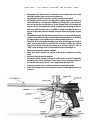
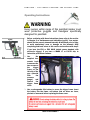
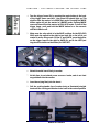
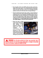
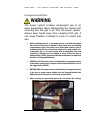
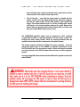
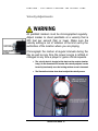
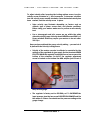
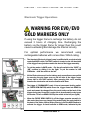
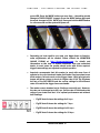
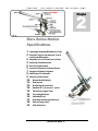
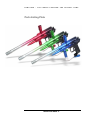
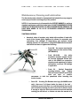
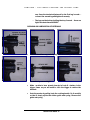
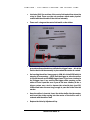
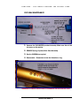
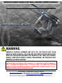
ARMOTECH MARS SERIES PAINTBALL MARKER OWNER’S MANUAL
WARNING
ARMOTECH PAINTBALL MARKERS ARE NOT A TOY. ANY MISUSE MAY CAUSE
SERIOUS INJURY OR DEATH. THE USER AND ANY PERSON WITHIN RANGE MUST
WEAR EYE PROTECTION DESIGNED FOR PAINTBALL USE. READ THIS OWNER’S
MANUAL COMPLETELY BEFORE LOADING, PRESSURIZING, OR OPERATING YOUR
ARMOTECH PAINTBALL MARKER.
This paintball marker is intended for sale to adults only, for use in compliance with all
applicable laws and regulations. Adult supervision is recommended at all times whenever a
minor is handling this paintball marker. All persons within range MUST wear protective
goggles & headgear specifically designed for paintball when a paintball marker is in use.
Paintball safety rules must be followed at all times.
Tactical Markers – Paintball Markers, Equipment, Supplies
www.tacticalmarkers.com Tel 1 856 753 2662 Fax 1 856 753 5758 [email protected]
online help forum http://team.tacticalmarkers.com/board/
ARMOTECH MARS EVO OWNER’S MANUAL, Compiled for ARMOTECH International, by John L.R. Dovale, Dangerous Enterprises
Table of Contents
CHAPTER 1
Paintball Safety Rules 1
Operating Instructions
3
Compressed Air/Gas 6
CO2 Safety
8
Velocity/PSI Adjust 10
E-Trigger Operations 13
CHAPTER 2
MARS Series Marker
Specifications
15
EVO Parts & Diag. 16
LT Parts & Diag.
18
Pluto Parts & Diag. 20
Maintenance &
Lubrication
21
Cup Seal Maint.
26
CHAPTER 3
Troubleshooting
127
Tips, Hints ‘n Tricks
(from our forum)
Warranty Info.
32
This owner’s manual is provided
with several models of the MARS
series paintball marker. Armotech
Inc reserves the right to modify or
change its markers without
incurring any obligation to
incorporate such modifications or
changes in any of its products
that were sold prior to the
modification. The information in
this owner’s manual may be
updated or changed without
notice.
This owner’s manual is intended
to remain with the paintball
marker upon any subsequent
transfer of the marker, whether
through sale, resale, or furnishing
in any manner.
Tactical Markers – Paintball Markers, Equipment, Supplies
www.tacticalmarkers.com Tel 1 856 753 2662 Fax 1 856 753 5758 [email protected]
online help forum http://team.tacticalmarkers.com/board/
ARMOTECH MARS EVO OWNER’S MANUAL, Compiled for ARMOTECH International, by John L.R. Dovale, Dangerous Enterprises
A R M O T E C H
–
T H E
P E R F EC T
M A R K E R … T H E
P E R F E C T
G A M E
1
Chapter
Paintball Safety Rules
Safety First!
WARNING
ARMOTECH PAINTBALL MARKERS ARE NOT A TOY. ANY MISUSE
MAY CAUSE SERIOUS INJURY OR DEATH. THE USER AND ANY
PERSON WITHIN RANGE MUST WEAR EYE PROTECTION
DESIGNED FOR PAINTBALL USE. READ THIS OWNERS’S
MANUAL COMPLETELY BEFORE LOADING, PRESSURIZING, OR
OPERATING YOUR ARMOTECH PAINTBALL MARKER.
•
•
•
•
•
•
•
Always wear protective goggles & headgear designed for paintball when shooting
this marker
Everyone within range of an area where this paintball marker is used should wear
protective goggles and headgear specifically designed for paintball
Operate this paintball marker only in areas where it is safe and lawful to do so
Misuse of this marker may result in criminal charges or imprisonment
This marker is intended for sale to adults. Adult supervision is recommended at
all times whenever a minor is handling this marker
READ THIS OWNER’S MANUAL COMPLETELY BEFORE LOADING, PRESSURIZING,
OR OPERATING THE ARMOTECH MARS SERIES PAINTBALL MARKER!
Never aim or shoot this paintball marker towards anybody who is not wearing
protective goggles or headgear specifically designed for paintball
MARS / PLUTO SERIES 1
A R M O T E C H
•
•
•
•
•
•
•
•
•
•
•
–
T H E
P E R F EC T
M A R K E R … T H E
P E R F E C T
G A M E
During game play, follow referee’s instructions and all field safety rules. Avoid
shooting at another player’s head, neck or groin area
Play paintball only where the rules of safety for paintball are followed
All paintball markers must be chronographed regularly. Adjust the marker to
shoot paintballs at a velocity this is 300feet per second (fps) or less and that
does not exceed the velocity limit set by the Paintball Park or field where the
marker is in use. Chronograph the marker at regular intervals during the day, as
well as any time the power source is refilled or changed, any time the barrel or
any part of the power system is changed, and upon request of any player or game
official
This paintball marker operates using compressed gas or air at specified pressure
ranges. Follow safety procedures when handling compressed gas or air. All filling
of compressed gas or air cylinders must be done by qualified persons
Follow the rules of safe marker handling: keep finger off the trigger until ready to
shoot. Keep muzzle pointed in a safe direction. In addition, firmly insert a barrel
plug into the muzzle and push the mechanical or electronic safety to “ON” or
“SAFE” when the marker is not in use and when in any non-shooting area
Never shoot at domestic animals or wildlife
Never mark objects outside the confines of the game or authorized shooting
areas
Never look down the barrel of a marker
Before disassembly, storage, or transport of this marker, remove ALL paintballs
from the marker, barrel, and loader: remove power source: and remove all gas or
air from the power system. Insert a barrel plug and put the safety “ON”
Carry your marker in a case or sturdy bag when transporting it in public
Safely and securely store marker to prevent access to it by unauthorized persons
or minors.
MARS / PLUTO SERIES 2
A R M O T E C H
–
T H E
P E R F EC T
M A R K E R … T H E
P E R F E C T
G A M E
Operating Instructions
WARNING
Every person within range of this paintball marker must
wear protective goggles and headgear specifically
designed for paintball.
1. Before continuing with these instructions please refer to the section
in Chapter 2 on maintenance and lubrication (pg 16). Your marker
should first be properly cleaned internally & lubricated prior to firing
to avoid unnecessary wear or damage on the internals. After
completing that task, return to this section and continue with step 2
if you have the EVO or EVO GOLD (which comes standard with
electronic trigger). If you have a MARS LT or PLUTO skip to
instruction point 5 and continue.
2. Use
the
supplied hexwrench tools
to unscrew the
two screws on
the
trigger
frame on the
left side of the
gun – (the side
with
the
pressure
gauge)
and
remove
the
trigger frame
cover.
3. Use a rechargeable 9.6v battery to power the trigger frame. Insert
the battery into the frame, and ensure that no wires are loose,
pinched or unsecured before replacing the frame cover.
MARS / PLUTO SERIES 3
A R M O T E C H
–
T H E
P E R F EC T
M A R K E R … T H E
P E R F E CT
G A M E
4. Turn the trigger frame ON, by pressing the mode button at the back
of the trigger frame one time - the green LED should light up. This
signifies that the marker is in SEMI shot mode. Pressing the MODE
button again will put the marker in 3-BURST mode. Pressing MODE
one more time will put the marker in FULL AUTO mode. To turn off the
trigger frame, press and hold the MODE button for a few seconds
until ALL LEDs are off.
5. Make sure the safe switch is in the SAFE position. On the EVO/EVO
GOLD push the switch to the right to turn safe ON, or the left to put
marker in active firing mode. On the LT and PLUTO, press the button
on the trigger frame to the right for SAFE ON, and to the LEFT (red
ring should be visible on the button) for SAFE OFF.
6. Attach threaded barrel firmly to marker.
7. At this time do not attach power source or loader, and do not load
any paintballs into the marker.
8. Insert barrel plug firmly into the barrel.
9. Pull the cocking handle (top of marker body as illustrated) straight
back until the cocking mechanism locks back in the cocked position
MARS/PLUTO SERIES 4
A R M O T E C H
–
T H E
P E R F EC T
M A R K E R … T H E
P E R F E CT
G A M E
10. Turn the safety switch to the FIRE position and then squeeze the
trigger with an even pressure. The cocking knob should snap forward
into the un-cocked position. You have just dry-fired your Armotech
marker. Do this a few times until you are comfortable with this
operation and the feel of the marker when cocking, and firing it.
11. Using the supplied hex-wrench make certain to properly tighten all
screws on your marker. These include the trigger frame, the secure
positioning screws on the powerfeed, and the lug inside the back of
the bolt, which secures the cocking pin. Do not overtighten and take
care not to strip ANY of these screws. Tighten the screw holding the
cocking pin enough to still allow manual removal of the cocking pin
with minimal force – DO NOT TIGHTEN THIS ALL THE WAY DOWN – IT
CAN CAUSE DAMAGE TO THE FIELD STRIP COCKING PIN.
12. Attach the loader or hopper
to the vertical powerfeed by
slowly turning it clockwise
while applying a slight
downward pressure. Some
loaders may require their
feed-necks
to
be
sandpapered in order for
them to fit properly into the
powerfeed of the marker.
Please hold the marker by the
powerfeed when inserting the
loader to avoid stressing or
twisting the powerfeed itself.
MARS/PLUTO SERIES 5
A R M O T E C H
–
T H E
P E R F EC T
M A R K E R … T H E
P E R F E CT
G A M E
Compressed Air/Gas
WARNING
The power system contains compressed gas or air
when pressurized. Never disassemble the marker until
removing ALL the gas or air from the power system.
Always keep hands away from escaping CO2 gas. It
can cause frostbite if allowed to come in contact with
skin.
•
Before attaching any air or gas power source, read and understand
this section of the owner’s manual. Follow safety rules for handling
compressed air/gas. If any leaks occur in the power system, refer to
troubleshooting section or Armotech support. Use only cylinders for
compressed gas or air that comply with all applicable laws and
regulations, including but not limited to those of the US dept of
transportation, OSHA, Compressed Gas Association and/or American
Society for Testing and Materials.
•
VERTICAL AIR: The power source is attached by screwing the threads
of the tank or power source adapter into the threaded ASA in front of
the trigger frame (PLUTO)
•
BOTTOM LINE: The power source is attached by screwing the threads
of the tank or power source adapter into the threaded bottom line
ASA at the base of the grip or on the drop forward (EVO).
•
When cocking the pressurized marker do not release the cocking
MARS/PLUTO SERIES 6
A R M O T E C H
–
T H E
P E R F EC T
M A R K E R … T H E
P E R F E CT
G A M E
knob until after the cocking mechanism has locked back into the
cocked position. The marker is now ready to fire.
•
Test for function – now that the power source is loaded and the
marker cocked, turn the trigger frame ON (for electronic triggers),
and flip the safety switch to the FIRE position and squeeze the
trigger. The marker should shoot air, and the cocking knob should
cycle back to the cocked position ready to fire again. Repeat this
several times to get used to the action of the marker. You have now
fired your marker WITH loaded power source.
The ARMOTECH paintball marker may be powered by CO2, regulated
compressed air (HPA), or regulated nitrogen. From the source of gas or air
through the entire power system, there are varying pressures that are
applied to the marker and the components of the power system.
The marker requires a minimum of 450psi for proper operation – if you are
using CO2 please refer to the ANNEX on regulator adjustment for the
EVO/EVO GOLD and LT to learn how to adjust, control and properly maintain
your input pressure. The PLUTO marker does not have an inline regulator
system.
If you are using HPA please ensure that the HPA bottle regulator output is at
least 550 PSI.
MARS/PLUTO SERIES 7
A R M O T E C H
–
T H E
P E R F EC T
M A R K E R … T H E
P E R F E CT
G A M E
SAFETY RULES FOR HANDLING COMPRESSED
AIR OR GAS MUST BE FOLLOWED AT ALL TIMES!
OPERATING PRESSURES AND INPUT PRESSURE
•
Operating pressure range 450 p.s.i. to 1150 p.s.i. (Although some
markers have been known to operate at pressures as low as 330
p.s.i. or pressures over 1200 p.s.i. it is recommended that the
specified operating pressure of the Armotech marker be used in
order to avoid problems.)
•
Never exceed recommended pressures, as this may be dangerous to
you and damaging to the marker. Refer to the section on regulating
input pressures for the EVO/EVO GOLD and LT marker models. There
is further information on the different expansion chambers on each
of these markers in the ANNEX.
•
Do not leave a pressurized marker or cylinder in direct sunlight or
exposed heat source. Increased temperatures will increase the
internal pressure of the compressed gas or air and could cause
problems.
VALVE CYLINDER CONNECTION
•
The Valve on a cylinder is to remain screwed into the cylinder. Should
it loosen, the cylinder may detach from the valve with an extremely
dangerous force.
•
Every time a cylinder is filled, the connection between the valve and
cylinder must be inspected. If any looseness or leak is detected
between the valve and the cylinder, do not fill. Drain the cylinder and
have it inspected by qualified persons.
•
During filling if any looseness or leak is detected between the valve
and the cylinder, filling should be stopped and the cylinder should
immediately be drained to avoid problems.
FILLING COMPRESSED AIR/GAS
•
An overfill of any compressed air or gas cylinder can cause the safety
burst disk on the cylinder to rupture. A cylinder may rupture with
excessive force. Use properly rated disk only for the burst disk.
MARS/PLUTO SERIES 8
A R M O T E C H
–
T H E
P E R F EC T
M A R K E R … T H E
P E R F E CT
G A M E
•
A scale must be used for ALL CO2 fills to prevent an overfill. A
pressure gauge must be used for all compressed gas or air fills to
prevent overfills.
•
Many cylinders are required to have US Department of Transportation
hydrostatic tests done at periodic intervals. This interval varies
depending on the cylinder type. The date of the cylinder’s initial or
last testing appears on the cylinder. Out of date cylinders should not
be used.
•
Installing the Gas/Air Power Source
o Make sure the BARREL PLUG is placed in the barrel
o Put the trigger frame on SAFE
o Screw the compressed air/gas source into the ASA Bottom
line Adapter
o Tighten until you feel a solid stop
o Turn the gas/air on if it has an on/off valve, otherwise it
should be active and ready to go.
o Do not store the marker with power source installed and full
•
Removing the Gas/Air Power Source
o Always remove power source before performing disassembly
of marker
o Unload all paint from the marker and detach the
hopper/loader
o Put the trigger frame on SAFE, (or turn trigger frame OFF if it’s
the electronic version)
o If the power source has an on/off valve (EVO GOLD) – shut it
OFF. Otherwise point the marker in a safe position and slowly
unscrew the power source.
o You will hear some compressed gas/air escaping via a bleedhole while unscrewing the power source. If you prefer you can
fire the marker to release ANY pressure in the system, while
continuing to unscrew the power source.
o If the unscrewing is difficult the system still has too much
pressure in it – check to make sure the power source is OFF
(if it has an on/off valve), or to ensure it is completely
discharged before continuing. CO2 can cause damage to Orings. These need to be inspected regularly to avoid leaks.
MARS/PLUTO SERIES 9
A R M O T E C H
–
T H E
P E R F EC T
M A R K E R … T H E
P E R F E CT
G A M E
Velocity Adjustments
WARNING
All paintball markers must be chronographed regularly.
Adjust marker to shoot paintballs at a velocity that is
300 feet per second (fps) or lower. Make sure the
velocity setting is not in violation of the limit set by the
authorities of the location where you are playing.
Chronograph the marker at regular intervals during the
day as well as any time the power source is refilled or
changed or any time a player or game official requests.
•
The velocity knob is located at the back on the receiver (marker
body). On the Armotech EVO marker this velocity adjuster can be
turned by hand easily once the locking retainer screw is loosened.
•
The illustrations below show how to adjust the velocity screw.
MARS/PLUTO SERIES 10
A R M O T E C H
–
T H E
P E R F EC T
M A R K E R … T H E
P E R F E CT
G A M E
To adjust velocity after loosening the locking retainer screw, turn the
velocity screw clockwise in ½ turn increments. To decrease velocities
turn the velocity screw counter-clockwise. Once the desired velocity has
been reached, lock the velocity screw in place.
•
Note: velocity may fluctuate depending on factors such as
altitude, type of power source used, and climate conditions.
Before using your marker make sure to perform a safe velocity
test.
•
Use a chronograph and let’s ensure we are within the safely
allowable velocity range. Velocity should NEVER exceed 300 f.p.s.
Some paintball fields may require your marker to be set under
300 f.p.s.
Once you have achieved the proper velocity setting – you can lock it
in place with the Velocity Locking Screw.
•
Velocity of the marker can also be affected or controlled by the
settings of the regulated air/gas supply. On the Armotech MARS
EVO/EVO GOLD the regulator is adjusted from a hex-screw on the
bottom of the x-chamber. On the LT the regulator adjustment
screw is located on the bottom line ASA adapter just in front of
the pressure gauge.
•
The regulator is factory set to 450-500 p.s.i. To INCREASE the
input pressure turn the hex-screw COUNTERCLOCKWISE and fire
the marker 2-3 times. You should see the pressure reading on the
gauge change.
MARS/PLUTO SERIES 11
A R M O T E C H
•
–
T H E
P E R F EC T
M A R K E R … T H E
P E R F E CT
G A M E
To DECREASE the pressure turn the hex-screw CLOCKWISE and
fire the marker 2-3 times. You should see the pressure reading on
the gauge change.
LT OPERATING PRESSURE SHOULD NOT
EXCEED 900P.S.I.
MARS/PLUTO SERIES 12
A R M O T E C H
–
T H E
P E R F EC T
M A R K E R … T H E
P E R F E CT
G A M E
Electronic Trigger Operations
WARNING FOR EVO/EVO
GOLD MARKERS ONLY
If using the trigger frame to recharge the battery do not
exceed 3 hours of charging time. Recharging the
battery via the trigger frame for longer than this could
cause overheating and damage the internal circuitry
For optimal performance we recommend using
rechargeable batteries with no less than 180mA rating.
•
The Armotech Electronic trigger frame is outfitted with an electronically
controlled SAFE switch. The SAFE switch is located on the left-hand side
of the trigger frame just above and to the back of the trigger assembly.
•
To put the marker in SAFE mode – flip the safe switch to the “SAFE” or
“ON” position by sliding it to the right. To put the marker in LIVE
FIREmode – slide the switch to the left.
•
All the Electronics as well as the battery pack connection are accessible
by removing the grip frame cover on the left side of the trigger frame
(same side as the SAFE switch). After removing this cover carefully
examine the electronics and become familiar with them.
•
The trigger is TOURNAMENT ready. It has a tournament locking switch
(or FORCE SEMI SWITCH) which forces the trigger frame into SEMI fire
mode and cannot be changed from the mode button on the back of the
trigger during play. Some field require this to be activated in order to use
the marker. To turn on SEMI LOCK flip the switch to the left (see fig 5A)
•
When the FORCE SEMI SWITCH is off the trigger operates normally. In
this mode, the player can change firing modes using the mode button to
the back of the frame. With a battery inserted, click the MODE button to
activate the trigger. It should activate in SEMI mode, indicated by the
MARS/PLUTO SERIES 13
A R M O T E C H
–
T H E
P E R F EC T
M A R K E R … T H E
P E R F E CT
G A M E
green LED. Press the MODE button one more time – the setting should
change to TRIPPLE BURST (orange). Press the MODE button again and
the mode changes to FULL AUTO (red). Press and hold the MODE button
for a few seconds and the system will power off.
•
Depending on how sensitive you want your trigger frame to function,
some adjustments will be needed. Please consult the ARMOTECH
ONLINE FORUM at http://forum.armotech.com for details and
information on this task, or request assistance from your authorized
dealer. In most cases the marker should arrive with all the required
trigger frame settings pre-adjusted to optimal operation
•
Armotech recommends that this marker be used with some form of
agitated or force fed electronic loader/ball feeder if a player plans to use
burst mode or full auto mode on the trigger frame. Using an electronic
hopper will allow a player to shoot at a higher rate of fire. Fig 5E shows
the rate of fire DIP SWITCH and the various settings for the different
rates of fire which the trigger frame can handle.
•
The marker comes standard set to 6 balls per second (b.p.s.). However,
the rate can be changed up to 13 b.p.s. Set the rate of fire based on the
rating of your loader and test it for optimal performance and minimal
ball breakage.
o Fig 5E block A shows the settings for 6 b.p.s.
o Fig 5E block B shows the settings for 7 b.p.s.
o Fig 5E block C shows the settings for 10 b.p.s.
o Fig 5E block D shows the settings for 13 b.p.s.
MARS/PLUTO SERIES 14
A R M O T E C H
–
T H E
P E R F EC T
M A R K E R … T H E
P E R F E CT
G A M E
2
Chapter
Mars Series Marker
Specifications
1.
2.
Lightweight Aluminum Milled Receiver Body
Electronic Trigger Frame with semi, 3-burst,
and full-automatic modes
3. Adjustable rate of fire from 6 bps to 13 bps
4. Quickstrip Field Maintenance
5. Rear Velocity Adjustment
6. Low Pressure Expansion Chamber System
7. Integrated X-Chamber Regulator
8. Multi-Stage CO2 X-Chamber
9. Volumizer (bullet shaped)
10. Bottom Line ASA Adapter
11. Drop Forward
12. Braided High Pressure Lines
13. Standard 14” 1 piece barrel – ported
14. LED display on trigger frame
15. Top Cocking Blowback
16. Vertical Ball Feed
17. Angel Style Ball-Bearing Ball Detent
18. Pressure Gauge (mini)
19. .689 Caliber Bore
MARS/PLUTO SERIES 15
A R M O T E C H
–
T H E
P E R F EC T
M A R K E R … T H E
P E R F E CT
G A M E
Parts Listing & Diagrams (EVO/EVO GOLD)
1. EVO Receiver Body
3. Hex Nut Metal Ball Bearing Detent
5. Aluminum 1 Piece Venturi Bolt
7. Striker Hammer
9. Striker Buffer
11. Striker Receiver Cap
13. Velocity Locking Hex
15. Vertical ASA Threaded Section
17. Screw On Regulator ASA Section
19. Reverse Thread xchamber section
2. Vertical Power Feed
4. 14” Ported Barrel
6. Field Strip Cocking Pin
8. Striker Spring
10. Striker Spring Guide
12. Velocity Adjustment Screw
14. ASA Adapter Body
16. Internal Valve Pin Airflow Assembly
18. Regulator Bottom Section
20. X Chamber with braided hose
adapter
MARS/PLUTO SERIES 16
A R M O T E C H
–
T H E
P E R F EC T
M A R K E R … T H E
21. X Chamber C-Clip
23. Valve Body Retainer Fitting
25. Trigger Frame Body
27. Trigger Retaining Pin
29. Trigger Switch Retainer Pin
31. Safety ON/ OFF Switch
33. SEAR
35. Sear Adjustment Screw (Hex)
37. E-Trigger Circuit Board
39. Trigger Screws (39-1)Lock Washers
41. Aluminum Drop Forward
43. Volumizer Valve Pin Spring
45. Cup-seal
47. Valve O-rings (not shown)
49. Drop Forward Securing Hex Screws
51. Bottom line Pressure Cap/O-ring
(ns)
53. Grip Frame Cover hex Screws
55. Cocking Pin Bearing Spring
0-4 Valve O-Rings
0-7 Striker Hammer O-Ring
0-17 X Chamber ASA O-Ring
2-1 Powerfeed Adjuster/Securing Lugs
P E R F E CT
G A M E
22. Braided Macroline Airhose
24. Valve Body Retainer Pin
26. Double Trigger
28. Trigger Switch Retainer Pin
30. Sear Retainer Pin
32. Safety Switch Screws
34. Sear Solenoid Retaining Hex Screws
36. Automatic Trigger Solenoid
38. Trigger Switch
40. Left Side Trigger Frame Grip Cover
42. Volumizer Adapter
44. Cup Seal Air guide/Spring Retainer
46. Valve Pin
48. Turbo Valve Assembly
50. Bottom line ASA Adapter
52. Pressure Gauge
54. Cocking Pin Retainer Bearing
56. Cocking Pin Spring Retainer Lug
0-5 Venturi Bolt O-Rings
0-14 Vert. ASA Body O-Ring
16-1 Internal Regulator Airflow Venturi
NOTE:
The MARS EVO GOLD has the same parts list, with the
exception that the ASA adapter (Part #15) has a 10 degree
angle to it, and the barrel (Part #4) is a two-stage (4A/4B)
component.
Additionally the Bottomline (Part #50) on the EVO GOLD has an
on/off screw adjustment used to activate and de-activate the
airflow from the power source (bottle) .This on/off replaced Part
#51 on the standard EVO.
The front section of the venturi bolt (Part #5) on the EVO GOLD
is DELRIN.
The drop forward on the EVO GOLD (Part # 41) has a flame
design
MARS/PLUTO SERIES 17
A R M O T E C H
–
T H E
P E R F EC T
M A R K E R … T H E
P E R F E CT
G A M E
Parts Listing Diagram – (LT)
1. EVO Receiver Body
3. Hex Nut Metal Ball Bearing
Detent
5. Aluminum 1 Piece Venturi Bolt
7. Striker Hammer
9. Striker Buffer
11. Striker Receiver Cap
13. Velocity Locking Hex
15. Vertical ASA Threaded Section
17. Gas Thru Washer/Bezel
2. Vertical Power Feed
4. 14” Ported Barrel
6. Field Strip Cocking Pin
8. Striker Spring
10. Striker Spring Guide
12. Velocity Adjustment Screw
14. ASA Adapter Body
16. Internal Valve Pin Airflow
Assembly
18. N/A
MARS/PLUTO SERIES 18
A R M O T E C H
–
T H E
P E R F EC T
19. Reverse Thread xchamber
section
21. N/A
23. Valve Body Retainer Fitting
25. Trigger Frame Body
27. Trigger Safety ON/OFF pushrod
29. Trigger Adjustment Screw for
safety
31. Sear Setting Placeholder pin
33. Sear Tension Spring Holder
35. Sear Tension Spring
37. Trigger Frame Screws
39. Trigger Frame Grip Cover
41. Aluminum Drop Forward
43. Volumizer Valve Pin Spring
M A R K E R … T H E
P E R F E CT
G A M E
20. X Chamber end w/braided hose
adapter
22. Braided Macroline Airhose
24. Valve Body Retainer Pin
26. Double Trigger
28. Trigger Guard Screw
30. Trigger Retainer Pin
32. Sear Retainer Pin
34. SEAR
36. Trigger
38. Trigger Frame Screw Washers
40. Trigger Frame Grip Cover Screws
42. Volumizer Adapter
44. Cup Seal Air guide/Spring
Retainer
46. Valve Pin
48. Turbo Valve Assembly
50. Bottom line ASA Adapter
45. Cup-seal
47. Valve O-rings (not shown)
49. Drop Forward Securing Hex
Screws
51. Bottom line Pressure Cap/O-ring
52. Pressure Gauge
(ns)
53. Bottom Line Air Regulation Hex
54. Cocking Pin Retainer Bearing
Screw
55. Cocking Pin Bearing Spring
56. Cocking Pin Spring Retainer Lug
0-4 Valve O-Rings
0-5 Venturi Bolt O-Rings
0-7 Striker Hammer O-Ring
0-14 Vert. ASA Body O-Ring
0-18 X Chamber ASA O-Ring
16-1 Internal Regulator Airflow Venturi
2-1 Powerfeed Adjuster/Securing Lugs
IMPORTANT NOTE: MARS LT OPERATIONAL
RANGE IS 400-900 PSI.
MARS/PLUTO SERIES 19
A R M O T E C H
–
T H E
P E R F EC T
M A R K E R … T H E
1. Lightweight Aluminum Milled Receiver Body
2. Composite Semi-Trigger Frame
3. Quickstrip Field Maintenance
4. Rear Velocity Adjustment
5. Low Pressure Expansion Chamber System
6. Integrated Bottomline Regulator
7. Multi-Stage CO2 X-Chamber
8. Volumizer (bullet shaped)
9. Bottom Line ASA Adapter
10. Drop Forward
11. Braided High Pressure Lines
12. Standard 14” 1 piece barrel – ported
13. Top Cocking Blowback
14. Vertical Ball Feed
15. Angel Style Ball-Bearing Ball Detent
16. Pressure Gauge (mini)
17. .689 Caliber Bore
MARS/PLUTO SERIES 20
P E R F E CT
G A M E
A R M O T E C H
–
T H E
P E R F EC T
M A R K E R … T H E
Parts Listing Pluto
MARS/PLUTO SERIES 21
P E R F E CT
G A M E
A R M O T E C H
–
T H E
P E R F EC T
M A R K E R … T H E
P E R F E CT
G A M E
Maintenance, Cleaning and Lubrication
The Armotech marker should be cleaned and lubricated after every usage to
ensure proper function and longevity of the product.
NOTE: It is not necessary to disassemble the ENTIRE MARKER to perform
standard maintenance and lubrication tasks. DO NOT DISASSEMBLE OTHER
AREAS OF THE MARKER UNLESS YOU ARE AN EXPERIENCED AIRSMITH, OR
HAVE BEEN ASKED TO DO SO BY AUTHORIZED ARMOTECH SERVICE
TECHNICIANS.
TIGHTENING SCREWS
•
Armotech ships all markers only lubed with machine oil and with
most of the screws lightly tightened to allows for expansion and
contracting from changes of temperature and pressure during
shipping process. As such before doing ANYTHING with the marker,
care should be taken to tighten the following:
o Parts 39 – the screws securing the
trigger frame to the receiver body
(ALL MODELS)
o Parts 18,19,20
- the entire
expansion chamber system should
be securely tightened. Please also
refer to the ANNEX on expansion
chambers and regulators for further
information on proper PSI settings
if applicable.
o Parts 2-1 – Vertical Powerfeed
securing/retainer lugs. Tighten
these to ensure that the power feed
does not spin, or wobble.
Remember to hold the powerfeed when inserting the
loader/hopper.
o Parts 56 – Cocking Pin Retainer hex lugs (On MARS series
only)– there are 2 of these inside the back of the bolt –
completely remove the first one, and then adjust the second
one so that the cocking pin can be removed by hand. Loosen
it enough to allow for hand removal but not so much that the
cocking pin will fall out, or vibrate out when the marker is in
MARS/PLUTO SERIES 22
A R M O T E C H
–
T H E
P E R F EC T
M A R K E R … T H E
P E R F E CT
G A M E
use. Once the desired adjustment for the first lug is made –
re-insert the second lug and tighten it securely.
o The lugs on the bottom holding the drop forward – these are
tight, but check them ANYWAY!
CLEANING AND LUBRICATION OF INTERNALS
•
Remove the striker cap/velocity adjustment assembly at the back of
the marker by unscrewing it.
•
Make certain to have already inserted a fresh 9 v battery in the
trigger frame as you will need to click the trigger to remove the
internals
•
Cock the marker by pulling back the cocking handle. Do it carefully
so that it slowly ejects the striker guide and spring. Remove the
guide and spring
MARS/PLUTO SERIES 23
A R M O T E C H
–
T H E
P E R F EC T
M A R K E R … T H E
P E R F E CT
G A M E
•
Remove the Cocking handle (MARS series – evo gold, evo, lt, all have
field strip pin aka cocking handle. The PLUTO is rear cocking and
does not have this feature)
•
Remove the Venturi bolt by pulling it out the back of the marker
•
Use an hex key wrench to guide the striker and striker buffer out the
back of the marker
With the internals removed you should be able to look through the
receiver body. In the top tube you should see the ball detent slightly
sticking out. In the bottom tube you should see the back of the valve
with the valve pin sticking through it.
•
With all the internals removed, run a squeegee through the receiver
body to clean it out – it is recommended that a latex/proflex
squeegee be used for this to avoid damage to the ball detent
•
The same squeegee can be reused (after cleaning it) to clean the
barrel of any residuals
•
The receiver body can be cleaned with a soft rag and warm water
(careful not to get any on the electronics of the trigger frame if the
marker has an e-trigger) or with a solvent such as WINDEX, which
dissolves the paintball residue nicely. DO NOT USE WINDEX TO
CLEAN YOUR GOGGLES. FOLLOW THE MANUFACTURERS
RECOMMENDATIONS FOR THAT PRODUCT!
•
Use warm, water or Windex to clean the venture bolt, and striker of
any residue and dry them with a lint free cloth.
•
Once dry, check the o-rings for any damage or loose fit. If you believe
the o-ring to be damaged or fitting loosely – replace it immediately.
Do not use the rubber bottle o-rings on your striker or barrel. Use only
the Urethane or Teflon o-rings for this purpose.
•
Also check the o-ring on the velocity adjuster cap to ensure it’s not
damaged.
•
Before re-assembling the internals, it is recommended that these be
properly lubricated. ONLY PAINTBALL GUN LUBRICATION is
recommended. DO NOT lubricate your internals with WD-40.
Acceptable lubricants are also TEFLON GREASE, SILICON GREASE.
MARS/PLUTO SERIES 24
A R M O T E C H
–
T H E
P E R F EC T
M A R K E R … T H E
P E R F E CT
G A M E
•
Lubricate ONLY the sections of the venturi bolt and striker where the
o-ring is fitted. These are the only sections which make physical
contact with the sidewalls of the receiver internally.
•
There are 2 o-rings on the venturi bolt and 1 on the striker.
•
Re-insert the striker first, making certain to orient it with the flat
grooved section pointed down towards the trigger frame – this is the
section that locks the assembly in place when the marker is cocked.
•
On inserting the striker it may seem to JAM- this is the SEAR which is
stopping it from passing – NOTE: Pull the trigger to allow the striker
to bypass the sear on the SEMI trigger frame. If you have a battery in
the e-trigger, turn it on, and fire the trigger while pressing on the
striker to force it past the sear. If you do not have a battery in the etrigger system, use a tool to depress the solenoid plate (part 36)
forward and lower the sear long enough to pass the striker into the
marker.
•
Once the striker is inserted, insert the striker buffer into the marker,
and insert the striker spring into the center of the buffer until it
contacts with the striker itself
•
Replace the Velocity Adjustment Cap
MARS/PLUTO SERIES 25
A R M O T E C H
–
T H E
P E R F EC T
M A R K E R … T H E
P E R F E CT
G A M E
•
Re-insert the venturi bolt – make sure that the grooved section on
the front side of the bolt is on the LEFT. This is the groove for the ball
detent. Inserting the bolt incorrectly can damage the bolt as well as
other internals of the marker. Slide the bolt as far in as possible
•
Make sure you can see the cocking pin alignment hole at the top of
the bolt – Insert the cocking pin and move the bolt slowly until you
feel it align with the cocking handle alignment hole for the striker.
•
Once the pin is in it will stick out only about ¾ to ½ inch at the top of
the marker- You should be able to cock the marker and feel the
tension of the spring. If not try aligning it more carefully.
•
Once this task is completed you have successfully maintained the
core section of your marker.
UNLESS YOU HAVE LEAKS THE INTERNALS (BOLT/STRIKER) ARE THE
ONLY SECTIONS THAT SHOULD BE REMOVED FROM THE MARKER ON A
REGULAR BASIS FOR CLEANING.
•
NEVER LET PAINT RESIDUE SIT IN THE MARKER OVERNIGHT – THE
CHEMICAL WILL ERODE THE O-RINGS.
RECOMMENDED LIST OF ITEMS WHICH SHOULD BE KEPT AS SPARES,
OR REPLACEMENT PARTS
•
Teflon or Urethane O-rings,
•
Rubber bottle and ASA O-rings,
•
ARMOTECH spare parts/spring kit
Extra 9v rechargeable battery if you have an e-trigger
Replacement cup seal (original or a black magic)
MARS/PLUTO SERIES 26
A R M O T E C H
–
T H E
P E R F EC T
M A R K E R … T H E
P E R F E CT
G A M E
CUP SEAL MAINTENANCE
1. Unscrew the VOLUMIZER (counterclockwise). Make sure there is NO
air source on the marker.
2. REMOVE Spring, Cupseal/Valve Stem Assembly
3. Service CUPSEAL as required
4. Reassemble – Remember to lube the Volumizer o-ring
REMEMBER TO LUBE THE VALVE O-RINGS IF YOU REMOVED AND REPLACED THE VALVE
MARS/PLUTO SERIES 27
A R M O T E C H
–
T H E
P E R F EC T
M A R K E R … T H E
P E R F E CT
G A M E
3
Chapter
Troubleshooting Tips,
Hints ‘n Tricks
•
Marker not firing:
o Check to ensure there is a 9 v battery in the e-trigger frame
(MARS EVO, EVO GOLD ONLY), and that is connected and has a
fresh charge.
o Check to ensure the trigger frame is ON by pressing the mode
switch 1 time (EVO & EVO GOLD)
o Check to ensure the safe switch is in LIVE FIRE mode (switched
to the left) (ALL MODELS)
o Check to ensure the marker is cocked
o Check to ensure that the attached power source (bottle) has
sufficient compressed air/gas in it to power the marker. Min
pressure required is 450 p.s.i.
•
I hear a hissing sound when I attach the power source:
o Check the o-ring on the air supply bottle – it may not look worn
but could be – and will leak
o If leak is not at bottle attachment, check the airhose connections
to ensure they are not leaking. If they are, they may require
tightening. Remove the expansion chamber from the marker prior
to tightening these fittings. Use proper wrench for this task to
avoid damage to marker or fittings.
MARS/PLUTO SERIES 28
A R M O T E C H
–
T H E
P E R F EC T
M A R K E R … T H E
P E R F E CT
G A M E
o If leak is not at the hose, check the o-rings on the expansion
chamber to ensure they are not damaged
o Check the o-rings on the volumizer to ensure it is not damaged or
leaking
o If none of these sections are leaking, check the cup-seal to make
sure it is sitting properly against the valve. In most cases the first
leak that you will encounter will be at the bottom line – o-ring on
the air supply bottle. The other most common leak that could
occur after some time is the cup-seal. This is easily replaced with
an Armotech cup-seal or any spyder compatible equivalent – the
BLACK MAGIC cup-seal is highly recommended to cure cup-seal
leaks.
o There is an o-ring under the pressure screw to the front of the
bottom line. DO NOT unscrew this.
o If you are still experiencing a leak, it could be that the regulator
on the expansion chamber needs to be adjusted. Follow the
instructions in this manual for making those adjustments.
•
I cannot get the cocking pin out of the marker (MARS SERIES ONLY):
o The cocking pin is held in place by pressure exerted by a springloaded ball-bearing system. This system is controlled by
tightening or loosening of a hex lug on the inside rear of the bolt.
o Remove the first hex-lug and use the same hex wrench key to
loosen the second lug and release pressure on the bearing just
enough to allow hand-removal of the cocking pin. Reinsert and
tighten the other lug to keep this setting in place.
•
I cannot cock the marker:
o Remove the velocity adjuster cap and examine the striker pin
section to ensure it is assembled properly
o Adjust the sear on the trigger frame to lower the sear as it may be
too high (hard) and stopping the striker hammer from moving
o Check the hex screw at the back of the trigger frame as it may be
too tight and causing a misalignment problem
MARS/PLUTO SERIES 29
A R M O T E C H
–
T H E
P E R F EC T
M A R K E R … T H E
P E R F E CT
G A M E
o If this jam occurred after a ball break, carefully check to ensure
there is residual skin fragments of the ball stuck between the
receiver housing and the barrel
o Check to ensure the powerfeed is not turned and blocking the
venture path
o If this jam occurred not from a ball break, carefully disassemble
the internals and check to see if the o-rings are not dislodged or
broken
•
The marker shoots once and does not re-cock:
o The o-ring on the striker hammer could be damaged and needs
replacing
o Check the cup seal to ensure the whole assembly is sitting
properly and is not leaking
o Check your air supply to ensure you have sufficient pressure to
operate the marker
•
The marker fires and continues to rapid fire, the re-cock does not hold:
o The sear adjustment is too low – check the section on trigger
adjustments and make the appropriate changes to correct the
problem
o Check the screws which hold the trigger frame to the receiver – if
they are loose – tighten them, in particular the rear screw
o The battery on the trigger could be LOW and in need of
replacement
•
The marker is set to SEMI mode but requires multiple trigger pulls to fire
once:
o The battery in the trigger frame is LOW or dying. Replace it!
o Check the sear adjustment - it may be too high
•
Balls break in the breach when attempting 3-burst mode or full auto:
o Check your trigger frame firing rate (bps) settings on the RED
dipswitch. It could be set too high.
MARS/PLUTO SERIES 30
A R M O T E C H
–
T H E
P E R F EC T
M A R K E R … T H E
P E R F E CT
G A M E
o Check your hopper/loader to ensure balls are not jamming inside
it.
o Use an electronic hopper, or force fed loader for best
performance.
•
Balls are not flying straight when fired:
o Clean the barrel with a squeegee
o Make sure the balls are the correct size/caliber for the bore of
the marker .689
•
Balls roll out of the barrel or shoots 2 at a time:
o Ball bore is too small. It needs to be .689
o Armotech recommends using tournament quality paint
•
§
RPS / PMI Brand (Big Ball/Warrior, El Tigre, Slam, All
Star, Premium, Premium Gold, Marballizer)
§
TC Paintballs (Viper Venoms, Viper Platinum, Pro Series)
§
Nelson Paintballs (Nel Splat, Anarchy, Nelson Gold)
§
PowerBall Paintballs
Barrel threads look worn down and barrel wobbles a bit
o Check to ensure barrel o-ring is in place properly
o Always use some grease type lubricant on the threads to avoid
metal-to-metal wear
•
Balls shoot but they do not appear to go the distance:
o Adjust the velocity and check it with a chronograph
o Check to ensure the striker spring is not damaged, weakened or
broken
o Check your air supply to ensure there is sufficient pressure
MARS/PLUTO SERIES 31
A R M O T E C H
–
T H E
P E R F EC T
M A R K E R … T H E
P E R F E CT
G A M E
o Check to ensure regulator settings are properly adjusted. Min
pressure should not be less than 450 p.s.i.
•
Vertical powerfeed wobbles a bit when hopper is attached
o Check to ensure the retainer screws have not come undone
o Always hold the powerfeed when attaching or removing the
hopper to avoid stressing it or damaging its seating on the
marker
MARS/PLUTO SERIES 32
A R M O T E C H
–
T H E
P E R F EC T
M A R K E R … T H E
Warranty Information
MARS/PLUTO SERIES 33
P E R F E CT
G A M E
A R M O T E C H
–
T H E
P E R F EC T
M A R K E R … T H E
P E R F E CT
G A M E
SUGGESTED ITEMS FOR PROPER MAINTENANCE
Flexible Squeeqee
Rod Squeege with Swab on the end
Cleaning cloths (soft terry-cloth material)
Paintball Marker Lubrication (OIL designed for paintball markers , or Teflon
grease)
Rechargeable Battery Packs for the e-trigger
o-ring and spring replacement kit (as a spare)
hex-wrenches of various sizes (marker comes with most commonly needed
ones)
Barrel Plug or Condom
MARS/PLUTO SERIES 34