1
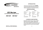
OWNER’S MANUAL
®
www.arcaudio.com
XDi 1200.6
Full Range Class D Amplifier
Introduction
Finding a Suitable Location
Supplying Power
The Ground
Running the Cables
Class D amplifiers
Diagnostic Fault Codes
Controls and Features
Inputs
Gains
Crossovers
Remote Level Control
Bass Boost
Ohm Load Matching
Speaker Outputs
Bandpass Crossovers Expalined
Installation Instructions
System Diagrams
4 Channel Stereo W/Subwoofer
3-WAY ACTIVE
TWEETER/MIDBASS SUBWOOFER
1
1
1
1
2
2
2
3
3
3
3
4
4
4
5
7
8
9
3-WAY MIXED ACTIVE
TWEETER/MIDRANGE
MIDBASS SUBWOOFER
3-WAY ACTIVE
TWEETER MIDRANGE MIDBASS
10
11
BRIDGED 3 CHANNEL
STEREO FRONT WITH SUBWOOFER 12
Input Select Switches
Auto Detect
Speaker Level Input
Specifications
Warranty
13
14
14
15
15
Thank you for purchasing an ARC Audio Hi-Performance Amplifier.
This ARC Audio amplifier uses a Full Range Class D architecture that significantly improves efficientcy, lowers heat output
and current draw. Don’t be fooled by the small size. Class D amplifiers make more power for their size than traditional
designs, making installation a breeze without compromising storage space.
ARC Audio...SOLID CONSTRUCTION for SOUND Car Audio Systems.
Warning
We build all ARC Audio products to play at high volumes for extended periods of time. Your ears however are not
designed for high volume listening. This product can easily generate volume levels that can permanently damage your
hearing. We urge you to limit your exposure to very high volume sound.
You may also find your state has laws governing the volume of an audio system in a car. Please be aware of all local and
state laws in you area.
A properly tuned and operated audio system will deliver years of enjoyment when used properly.
Installation Instructions
ARC Audio XDi Amplifiers are designed for easy installation in your vehicle. To ensure proper operation of your new
purchase, please follow the suggestions we have listed below:
Warning
Please check the suitability of the installation location before you begin. Do not cut any of the car’s structure. Pay close attention
to what is behind the panels or carpet. Often the manufacture will hide wires, computers or other electronic devices in the exact
areas you wish to install in.
If you do not have experience with automotive electrical and mechanical systems contact a professional installer. Paying a
qualified installer is almost always cheaper then paying a dealership to repair your car.
Locating the Amplifier
The amplifiers must be securely mounted to a solid surface. Please select a dry location in the trunk or passenger compartment only. Do not mount the amplifier to any area that may have excessive vibration (like the subwoofer box). Position the
amplifier in an area that receives sufficient airflow for proper heat dissipation.
Supplying Enough Power
The Laws of Nature
Your amplifier Does NOT make power. It converts power, or current, from your cars electrical system and turns it into a high
power musical energy. If the amp can't get all the power it needs it will not produce its full output. Your ARC Audio amplifier will produce Full output for longer then other amps on the market today. If the Voltage or Current drops too low, even
our amplifiers will drop below their rated output. Make sure your vehicle charging system is in good working order. Any
Hi-Performance audio amplifier will increase the demand on your alternator and battery. If you are unsure have your
charging system tested by a professional technician.
The Ground!!!
Warning: Read this Carefully
The ground wire should be connected directly to the chassis of your vehicle. Find a clear location close to the amplifier
and remove all the paint and sound deadener. Use a #10 or larger screw to secure it. A nut, bolt and lock washer would be
better still. Never use seat belt bolts for grounding.
Remember, the ground must carry the same high current as the positive power wire.
To reduce the risk of noise, run all signal cables away from any vehicle or power supply wiring.
1
Running the Cables
Carefully run the power and signal cables through the passenger compartment of the vehicle. Running power down one
side and signal down the other is the preferred method. If this isn’t possible, keep them separated as much as possible.
When running through any metal, always use a rubber grommet to prevent the power wire from shorting and to reduce
the risk of fire. A 4 gauge or larger wire should be used for power and ground connections. ALWAYS install a fuse on the
power wire within 18 inches of the battery for safety.
Recommendations for all Class D amplifiers
Class D amplifiers by the nature of there design emit a certain amount of RF (Radio Frequency) radiation. While we have
optimized the design to reduce this to a minimum level, there are still steps you can take to eliminate any unwanted FM
radio interference. The tips below apply to any class D amplifier.
Always mount the amplifier as far from the antenna as the installation will allow. At the same time you will want to keep it
away from the radio or any other electronics that may prove to be sensitive to RF radiation.
Make the ground wire as short as possible. Think of the ground like it is an antenna. Short antennas do not work as well.
Use twisted pair wires as much as possible. If you can manage it, all the speaker wire and input cable weather by RCA or
speaker level should be twisted. If you do not have twisted pair wire you may be able to twist it yourself.
If you encounter a problem with FM interference you can try turning the amplifier 90 degrees or changing its location
completely. RF radiation can be very directional.
Warning
Take extra care when using CCA (Copper Clad Aluminum) or pure aluminum wire to insure the connections are clean
and tight. Due to aluminums highly reactive nature, these connections can fail without the typical "Green" or tarnished
look you would expect with copper. Aluminum also has a greater rate of expansion due to heat and care must be taken
to ensure that the connection is not over tightened. This can result in the failure of the power or ground connector and
possibly the circuit board.
DIAGNOSTIC FAULT CODES
The Amplifier has Over Heated. Turn the volume down and let it cool off.
Thermal (Transformer)
Long
Short
The Power Supply Transformer has Over Heated. Turn the volume down and let it cool off.
Code 11 Under Voltage
Short
You didn’t turn the system off, did you?
Code 14 Over Voltage
Your Alternator is Over-Charging. Have your vehicle’s electrical system tested right away.
Code 15 DC Output Protection
Long
Short
Short
Flash
Flash
Shorted speaker or wire on Channels 1-4. Turn the system off unill you can get this fault corrected. Also includes internal shorts.
Code 13 Repeated Shorts
Long
Flash
The Battery Voltage it too low. I bet your car won’t start. If it does, you have a bad connection.
Code 12 Short (Low Power Channel)
Long
Long
Thermal (Heatsink)
Short
Flash
Flash
Flash
Short
Flash
Flash
Flash
Flash
Short
Flash
Flash
Flash
Flash
Flash
DC Current was detected on the speaker line and to avoid damaging the speakers, this amplifier has shut down. This will probably require factory service.
Code 16 Short (High Power Channel)
Shorted speaker or wire on subwoofer channels (5 or 5-6) also includes internal shorts.
Normal Turn on
Blue is good. This is normal self test and turn on delay.
Power/Processor Reset
Short
Short
Short
Flash
Flash
Flash
Flash
Flash
Flash
Short
You will see this the first time the amplifier is powered up or the microprocessor resets. This code will vary from model to model.
2
Flash
Flash
Flash
Flash
Flash
Flash
Flash
Flash
Flash
Flash
Flash
Input Section
This XDi amplifier in equipped with a Balanced Input Stage that is compatible with any analog source including Balanced
and Unbalanced RCA, Common ground speaker level output or BTL (Bridged Tied Load) outputs common on many OEM
headunits. The RCA pigtails included with this amplifier are intended to be used with speaker level outputs and include a
divider network molded into the end to reduce the level of
the OEM system. If you are integrating into an OEM systems
balanced or common ground line level signal you should
not use these Pigtails. In this case it is recommended that
you use an appropriate RCA cable with 1 set of ends
removed as inputs for the amplifier.
Gain
Because of the wide range of head unit output configurations, all ARC Audio amplifiers have an adjustable input sensitivity
or “Gain”. The gain is not a volume or a power limiting control like a throttle. It makes the amp more sensitive to input from
the stereo. With the gain up the amp will reach full output at a lower volume setting on the deck. At higher gain settings
the amp also becomes more sensitive to noise from the car’s electrical system. Try to run the gain at the lowest setting
possible for you system.
There is no correct gain setting. Because speakers require
different power demands to reach the same output, the
gains most often need to be used to compensate for these
differences. If you tried to set all the gains at half way you
would probably find the system didn’t sound very good.
Using good judgment and listening carefully to each speaker
is still the best way to tune a system.
Crossover Controls
A crossover is a device that removes unwanted frequencies from a speaker or amplifier. A tweeter can easily be
destroyed by bass notes if they are not filtered out. Likewise a subwoofer will not sound natural if it is playing midrange
notes. A crossover removes these sounds from the speaker. As you might guess, careful adjustment is needed to ensure
that all the speakers are playing the right sounds and that
you are left with no “holes” or low spots in the frequency
response.
NOTE: Some of the crossovers on this model include a
X10 switch. This has the effect of multiplying the
frequency you set on the knob by 10. If the control is set
to 50Hz with the X10 applied the actual frequency will be
500Hz.
Remote Level Control
This amplifier is equipped with a remote level control for the front channels. This level control is used in conjunction
with the LOWPASS crossover. It DOES NOT work in highpass or full range. This control has the effect of reducing the
gain by -12dB. To use this control, set the gains to the maximum (SAFE and undistorted) volume you would use. The
remote is then used to adjust this level
down to a normal level. It will not mute
these channels completely.
This Does Not control the Bass Boost.
3
Bass Boost
This amp has an adjustable Bass Boost that is directed to the front speakers. When laying out your system, if you plan to
use Bass Boost (Example: Running a Bridged Subwoofer), connect those speakers to the front channels. Begin your adjustments at a low volume. If you do not hear any improvement,
then the woofer does not need any boost. Use Bass Boost
carefully. The demands on power output are tremendous.
Try to minimize its use by changing woofer position or the
enclosure size.
Ohm Load Matching
This amplifier is equipped with a unique impedance matching system that allows you to mix a wide range of Ohm loads
and still achieve full power. This can be done independently on the front and rear channels.
Under 4Ω
Any speaker or combination of speakers with a total combined Ohm load between 2 and 4 Ohms (not lower than 2
Ohms) must use this position. Bridged loads down to 4 Ohms must use this position. The amplifier will make full power at
2 Ohms Stereo (4 Ohms bridged). Note: you can use any Ohm load above 2 Ohms in this position, however power output will
drop as the impedance increases.
Over 4Ω
Any speaker or combination of speakers with a total
combined Ohm load over 4 Ohms can use this position.
The amplifier will make full power at 4 Ohms stereo (8
Ohms bridged).
WARNING: This amplifier will not operate and could be
damaged if used in the wrong configuration. At no time
can it be operated below 2 Ohms stereo or 4 Ohms
bridged.
Speaker outputs
This amplifier is a multi channel amplifier design, meaning it has more than one channel of speaker outputs. It is
equipped with a removable plug style terminal for speaker wire connections up to 14 AWG. Make this connection
carefully and neatly. Strip your wire back 5/16” and twist the exposed leads and insert them into the block terminal while
being careful that there are no loose or frayed strands of wire.
Tighten the standard head screw down on the terminal until
the wire is tightly secured in place. If the wires ever come in
contact with each other, the amplifier will go into protection.
Know your total Ohm load before you make any connections.
5/ “
16
8MM
Strip Speaker Wire
4
Bandpass Crossovers in 250 Words or Less
There are times when you would like to limit a speaker to a specific range of frequencies or sounds. A great example of
this is a midrange. You don't want it playing very low frequencies that might damage it. Smoked voice coils smell terrible.
To achieve this you need to use Bandpass crossover. A Bandpass will have 2 controls for frequency adjustment. Now here
is where it gets confusing. The "Highpass" control takes out the low frequencies. The "Lowpass" filters out the highs. I
know, I said it would be confusing but I'll try to make it easier to understand. Highpass means exactly that, it's passing the
high frequencies and blocking anything below the point you have set. So literally High Frequencies are Passed
(Highpass). Lowpass does just the opposite. It passes low frequencies while filtering out the highs.
OK got that? Here are a couple graphs that might help.
HIGHPASS
LOWPASS
BANDPASS
5
Now I'll introduce you to the controls on the XDi 1200.6.
HIGHPASS
With the crossover set in Highpass you will
be using the highpass frequency control. In
this case it is on the far left hand side however this may very from model to model. If
the crossover is set to FULL turning this
control will not do anything.
LOWPASS
In Lowpass you are using the Lowpass frequency
control.
BANDPASS
To achieve a Bandpass you need to have to Crossover switch selected to LOW and the Bandpass
selected to the ON position. You will now have a
working Bandpass.
NOTE: If the Highpass frequency is set higher
then the Lowpass frequency the 2 crossovers will
overlap and remove almost all signal. It is
possible to set this crossover so that nothing can
be heard from the speaker.
6
Installation Instructions
Below is a very abbreviated set of installation instructions. This is not meant as a step by step procedure, but is
intended to give you a general idea of what is involved and which steps come first. Every installation will be
different and may require reordering of these steps. NEVER install the fuse at the battery or connect the negative
battery cable until all your connections are final.
Before you start, disconnect the negative cable from any and all batteries in the car. Tape up the end so it is isolated
from the battery.
Run an appropriate gauge wire from the battery to the amplifier. Plan this part of the installation carefully. This
cable will carry very high current. If it should short to the body and it is not properly fused it could catch fire. You
DID use a grommet when you ran it through the firewall, didn’t you?
Connect the power wire to the battery using a fuse capable of the total current load of all amplifiers connected.
Don’t install the fuse yet. Wait until the end. Locate the fuse as close as possible to the battery. If the fuse is
further than 18 inches (wire length) from the battery, you should reevaluate the wire and fuse placement.
Find the closest clear metal area to the amp for a ground. Sand, grind or scrape all paint and undercoating from the
body and screw the ground securely in place. A nut, bolt and lock washer is advisable here.
It is advisable to test the ground with an Ohmmeter between the ground cable and the negative battery cable to
insure a good low resistance connection. Some alloys used in modern cars do not offer the best ground. If you
believe this is the case, consult with the vehicle’s manufacturer.
Run the speaker wire to the speakers. It is advised that you leave some extra wire at this point. You can “clean it up”
later.
If you haven’t already done so, mount the amp now.
Connect the power and ground to the amplifier.
Only after this step should you install the fuse at the battery.
Connect the remote wire from the head unit to the amplifier. Now is a good time to turn on the amp for the first
time. Make sure it turns on properly and does not go into protection.
Connect the speaker wires to the amp and speakers (make sure the amp is off first). Make sure the polarity (+ and -)
is correct.
Connect the RCA signal wires to the amp.
Double check the amplifier controls at this time. Make sure everything is set correctly for your system.
Now you’re ready to play it for the first time. It is best to leave the gain all the way down at first. Start with the head
unit volume low and work your way up.
Now you can tune the amp. Take your time and make only one adjustment at a time. It may take some time to get
the system fully adjusted. During this time the amp is drawing current from the battery. You should check the
battery voltage from time to time and re-charge it if it gets low. That’s it. You’re done. Now have fun.
7
XDi 1200.6
4 CHANNEL STEREO
WITH BRIDGED SUBWOOFER
Use this
Crossover
for HIGH
Set to
X1
Set to
HIGH
Set to
OFF
Use this
Crossover
for HIGH
Set to
4CH STEREO
Not
Used
Not
Used
Set to
HIGH
Use this
Not Crossover
Used for LOW
Set to Set to
Not
X1 LOW
Used
Set to
MONO
4Ω
+
OPTIONAL
SECOND SET
FINAL LOAD WILL BE
2 OHM STEREO
OPTIONAL
SECOND SET
FINAL LOAD WILL BE
2 OHM STEREO
8
XDi 1200.6
ACTIVE 3-WAY
TWEETER/MIDBASS
SUBWOOFER
Use this
Crossover
for HIGH
Set to
X10
Set to
ON
Set to
4CH STEREO
Set to
HIGH
Set to
X10
Use this
Use this
Crossover
Crossover
for WOOFER for WOOFER
SUBFOOFER TWEETER
XOVER
XOVER
Set to
LOW
Use this
Not Crossover
Used for LOW
Set to Set to
Not
X1 LOW
Used
Set to
MONO
4Ω
+
Tweeter
Midbass
Driver
OPTIONAL
SECOND SET
FINAL LOAD WILL BE
2 OHM STEREO
9
XDi 1200.6
3-WAY MIXED ACTIVE
TWEETER/MIDRANGE
MIDBASS
SUBWOOFER
Use this
Crossover
for HIGH
Set to
X1
Set to
ON
Set to
4CH STEREO
Set to
HIGH
Set to
X1
Use this
Use this
Crossover
Crossover
for MIDBASS for MIDBASS
SUBFOOFER MIDRANGE
XOVER
XOVER
Set to
LOW
Use this
Not Crossover
Used for LOW
Set to Set to
Not
X1 LOW
Used
Set to
MONO
4Ω
Tweeter
Midrange
+
Midbass
Driver
OPTIONAL
SECOND SET
FINAL LOAD WILL BE
2 OHM STEREO
10
XDi 1200.6
3-WAY ACTIVE
TWEETER/MIDRANGE
MIDBASS
Use this
Crossover
for HIGH
Set to
X10
Set to
ON
Set to
4CH STEREO
Set to
HIGH
Set to
X10
Use this
Use this
Crossover
Crossover
for MIDRANGE for TWEETER
MIDRANGE
MIDBASS
XOVER
XOVER
Set to
LOW
Use this
Use this
Crossover for Crossover for
MIDBASS
MIDRANGE
SUBWOOFER MIDBASS
XOVER
XOVER
Set to
NO
Set to
MONO
Set to Set to
X1 LOW
Tweeter
Midrange
Driver
OPTIONAL
SECOND SET
FINAL LOAD WILL BE
2 OHM STEREO
11
Midbass
Driver
XDi 1200.6
BRIDGED 3 CHANNEL
STEREO FRONT
WITH SUBWOOFER
Set to
4CH MONO
Not
Used
Not
Used
Not
Used
Set to
OFF
Use this
Crossover
for HIGH
Not
Used
Not
Used
Set to
HIGH
Use this
Not Crossover
Used for LOW
Set to Set to
Not
X1 LOW
Used
Set to
MONO
4Ω
+
Front
Rear
12
XDi 1200.6
INPUT SELECT
SWITCHES
Set to
4CH
Set to
SUB
From Head Unit Front RCA Output
From Head Unit Rear RCA Output
From Head Unit Subwoofer Output
Set to
4CH
Set to
FRONT
From Head Unit Front RCA Output
From Head Unit Rear RCA Output
Set to
2CH
Set to
FRONT
From Head Unit Front RCA Output
13
XDi 1200.6
AUTO DETECT
SPEAKER LEVEL INPUT
AUTO SENSE
The XDi 1200.6 uses BTLD (Bridge Tied Load Detect) Turn-on circuit
that offers a significant improvement in reliability over previous
designs. Instead of relaying on the music to supply enough signal to
turn the amplifier on. Robert Zeff’s design detects the IC (chip) used
in the vast majority of stock head units and amplifiers.
When using the auto sense feature the remote input on the power
strip becomes a remote output reversing the remote turn-on
connection to turn on the rest of your amplifiers?
NOT USED
From Head Unit Right Front Speaker Output
From Head Unit Left Front Speaker Output
From Head Unit Right Rear Speaker Output
From Head Unit Left Rear Speaker Output
From Right Subwoofer Output if Present
From Left Rear Subwoofer Output if Present
14
AUTO SENSE
DETECTS ON
THIS CHANNEL
SPECIFICATIONS
FIVE CHANNEL AMPLIFIERS
FOUR CHANNEL AMPLIFIERS
XDi 450.4
4 Channels @ 4 ohms4 Channels @ 2 ohms2 Channel @ 4 ohmsFrequency ResponseTotal Harmonic Distortion
Bass BoostRemote IncludedXDi Trim KitDimensions-
XDi 600.4
85 Watts
125 Watts
250 Watts
20Hz - 20kHz
.08% THD
12dB @45Hz(Rear only)
No
Not Included
8.173”(L) x 6.268”(W)
x 2.086” (H)
XDi850.5
150 Watts
150 Watts
300 Watts
20Hz - 20kHz
.02% THD
12dB@45Hz(Front Only)
Yes
Included
9.020“ (L) x 6.268” (W)
x 2.162 (H)
MONO BLOCK AMPLIFIERS
XDi650.1
1 Channels @ 4 ohms1 Channels @ 2 ohms1 Channel @ 1 ohmsFrequency ResponseTotal Harmonic Distortion
Bass BoostRemote IncludedXDi Trim KitDimensions-
185 Watts
350 Watts
650 Watts
20Hz - 20kHz
.05% THD
12dB@30-125Hz
Yes
Not Included
9.02”(L) x 6.268”(W)
x 2.086” (H)
4 Channels @ 4 ohms4 Channels @ 2 ohms2 Channel @ 4 ohms1 Channel @ 4 ohms1 Channel @ 2 ohmsFrequency ResponseFrequency Response(sub)Total Harmonic Distortion
Bass Boost(Sub Ch)Remote IncludedXDi Trim Kit
Dimensions-
85 Watts
125 Watts
250 Watts
225 Watts(Sub Channel)
400 Watts(Sub Channel)
20Hz - 20kHz
20Hz - 230Hz
.08% THD
12dB@45Hz
Yes
Not Included
XDi1100.5
150 Watts
150 Watts
300 Watts
275 Watts(Sub Channel)
500 Watts(Sub Channel)
20Hz - 20kHz
20Hz - 230Hz
.02% THD
12dB@45Hz
Yes
Included
12.42”(L) x 6.268”(W) 12.42”(L) x 6.268”(W)
x 2.086” (H)
x 2.162” (H)
SIX CHANNEL AMPLIFIERS
XDi1200.6
XDi1100.1
350 Watts
600 Watts
1100 Watts
20Hz - 20kHz
.06% THD
12dB@30-125Hz
Yes
Included
13.0“ (L) x 6.268” (W)
x 2.162 (H)
4 Channels @ 4 ohms4 Channels @ 2 ohms2 Channels @ 4 ohms2 Channels @ 4 ohms2 Channel @ 2 ohms1 Channel @ 4 ohmsFrequency ResponseTotal Harmonic Distortion
Bass BoostRemote IncludedXDi Trim KitDimensions-
150 Watts
150 Watts
300 Watts
150 Watts (Ch 5&6)
300 Watts (Ch 5&6)
600 Watts (Ch 5&6)
20Hz - 20kHz
.02% THD
12dB @ 45Hz (Ch 5&6)
Yes
Included
13.0”(L) x 6.268”(W)
x 2.162” (H)
ARC AUDIO WARRANTY
ARC AUDIO warranties all new XDi Amplifiers against defects in material and workmanship for a period of ONE (1)
YEAR from the original date of purchase. This warranty is not transferable and applies only to the original retail purchaser
of the product from an authorized ARC AUDIO retailer. Upon inspection by ARC AUDIO should services be necessary under
this warranty for any reason due to manufacture defects ARC AUDIO will, at its sole discretion, repair or replace the defective
product with new or similar conditioned product at no charge.
THIS WARRANTY DOES NOT COVER INSTALLATION OR DAMAGE RESULTING FROM ACCIDNT,
MISUSE, ABUSE, IMPROPER WIRING, OPERATION OUTSIDE OF THE MANUFACTURER’S
RECOMMENDATIONS OR SPECIFICATIONS, OR AGAINST INSTRUCTIONS IN THE OWNERS MANUAL. IN
ADDITION ANY PRODUCT THAT HAS BEEN OPENED, TAMPERED WITH OR MODIFIED, OR IF ANY SERIAL
NUMBERS HAVE BEEN REMOVED WILL NOT BE COVERED BY ANY PART OF THE MANUFACTURES
WARRANTY.
All warranty returns should be sent to ARC AUDIO freight prepaid and must be accompanied by proof of purchase (a
copy of the original sales receipt). Direct returns from consumers or non-authorized retailers will be refused unless specifically
authorized by ARC AUDIO with a valid return authorization number.
All warranty returns should be packed in original packaging and must be accompanied by a copy of the original
sales receipt. Product damaged in shipment will not be covered under this warranty. The customer or retailer may choose
to have this damage repaired at the normal “Out of Warranty” repair cost.
In no event will ARC AUDIO be liable for incidental, consequential, or other damages resulting from the use of this
product, this includes but is not limited to, damage of hearing, property or person, damage based upon inconvenience or on loss of
use of the product, and to the extent permitted by law, damages for personal injury. This warranty gives you specific legal rights,
and you may have other rights, which vary from state to state. This warranty applies to products sold and used in the United States
of America. In all other countries please contact your distributor
15