1
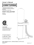
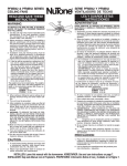
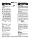
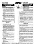
MODEL 512
ROOM TO ROOM FAN
MODELO 512 VENTILADOR DE
HABITACION A HABITACION
READ AND SAVE
THESE INSTRUCTIONS
WARNING
LEA Y CONSERVE
ESTAS INSTRUCCIONES
ADVERTENCIA
TO REDUCE THE RISK OF FIRE, ELECTRIC
SHOCK, OR INJURY TO PERSONS, OBSERVE THE
FOLLOWING:
1. Use this unit only in the manner intended by the
manufacturer. If you have questions, contact the
manufacturer at the address or telephone number
listed in the warranty.
2. Before servicing or cleaning unit, switch power off
at service panel and lock the service disconnecting means to prevent power from being switched
on accidentally. When the service disconnecting
means cannot be locked, securely fasten a prominent warning device, such as a tag, to the service
panel.
3. Installation work and electrical wiring must be done
by a qualified person(s) in accordance with all applicable codes and standards, including fire-rated
construction codes and standards.
4. Sufficient air is needed for proper combustion and
exhausting of gases through the flue (chimney) of
fuel burning equipment to prevent backdrafting.
Follow the heating equipment manufacturer’s
guideline and safety standards such as those published by the National Fire Protection Association
(NFPA), and the American Society for Heating,
Refrigeration and Air Conditioning Engineers
(ASHRAE), and the local code authorities.
5. When cutting or drilling into wall or ceiling, do not
damage electrical wiring and other hidden utilities.
6. DO NOT CREATE AN OPENING IN A FIRERATED WALL TO INSTALL THIS FAN. It is not an
exhaust fan, rather it is intended to direct air from
one room to another.
7. This unit must be grounded.
CAUTION
1. For general ventilating use only. Do not use to
exhaust hazardous or explosive materials and vapors.
2. To avoid motor bearing damage and noisy and/or
unbalanced impellers, keep drywall spray, construction dust, etc. off power unit.
3. Please read specification label on product for further information and requirements.
TOOLS AND
MATERIALS REQUIRED
❏
❏
❏
❏
❏
❏
❏
Pencil and ruler or tape measure
Straight-blade screwdriver
3/16” drill bit
Drill, electric or ratchet drive
Pliers
Drywall saw or saber saw
Electrical supplies of type to comply with local
codes
INSTALL THE FAN
1. Plan installation. Fan will install in walls up to
5–1/8” thick. For wall less than 4–1/2” thick, a trim
board frame for spacing is required (see Step 13).
Fan can be controlled by a wall switch or speed
control (available separately).
2. Carefully cut out fan openings and switch box opening. (FIG. 1)
CAUTION: BE SURE TO MEASURE AND MARK
CENTER OF FAN OPENING ON OPPOSITE WALL
BEFORE CUTTING OUT EITHER OPENING.
WARNING: WHEN CUTTING OR DRILLING INTO
WALL, BE CAREFUL NOT TO CUT EXISTING ELECTRICAL WIRING.
FIG. 1
SWITCH OR
SPEED
CONTROL
INTERRUPTOR
O CONTROL DE
VELOCIDAD
FAN
VENTILADOR
WALL OUTLET
ENCHUFE DE
PARED
FAN HOUSING FLANGE
BORDE DE LA CARCASA
DEL VENTILADOR
FIG. 2
GRILLE
REJILLA
AIRFLOW DIRECTION
(INLET)
BRACKET TAB
PESTAÑA DEL
SOPORTE
DIRECCIÓN DEL FLUJO
DE AIRE (ENTRADA)
MOUNTING
BRACKET
SOPORTE DE MONTAJE
FAN HOUSING
LA CARCASA
DEL VENTILADOR
FIG. 3
WIRING BOX
CAJA DE
GREEN OR BARE CONEXIONES
WIRE
CABLE VERDE O
DESCUBIERTO
WHITE WIRES
CABLES BLANCOS
COVER
TAPA
BLACK
WIRES
CABLES
NEGROS
FAN
HOUSING
CARCASA DEL
VENTILADOR
PRECAUCION
FIG. 4
FAN HOUSING
CARCASA DEL
VENTILADOR
MOUNTING
BRACKET
SOPORTE DE
MONTAJE
FIG. 5
WIRING BOX
CAJA DE
CONEXIONES
PANELING
PANELADO
WALL
PARED
3,2 - 6,3 mm
/8” - /4”
1
1
FRAME
MARCO
GRILLE
REJILLA
FIG. 6
PLASTER
YESO
WALL
PARED
PARA REDUCIR EL RIESGO DE INCENDIO, DESCARGA
ELECTRICA O LESIONES PERSONALES, CUMPLA CON
LOS SIGUIENTES PUNTOS:
1. Solamente use esta unidad de la manera propuesta por
el fabricante. Si tiene alguna pregunta, póngase en
contacto con el fabricante en la dirección o teléfono
anotados en la garantía.
2. Antes de limpiar o de poner en servicio la unidad, apague
el interruptor en el panel de servicio, y asegure el panel
de servicio para evitar que se encienda accidentalmente.
Cuando el dispositivo para desconectar el servicio
eléctrico no puede ser cerrado con algún tipo de traba,
sujete fuertemente al panel de servicio, una etiqueta de
advertencia prominente.
3. El trabajo de instalación y el alambrado eléctrico deben
de llevarse a cabo por personal competente de acuerdo
con todos los códigos y las normas correspondientes,
incluyendo los códigos y normas de construcción contra
incendios.
4. Se requiere una cantidad de aire suficiente para la
combustión y expulsión de gases por la chimenea en el
equipo de quemado de combustible para evitar la
retrogresión de la llama. Siga las especificaciones del
fabricante del equipo de calefacción y las normas de
seguridad semejantes a las publicadas por la Asociación
nacional de protección contra incendios (NFPA por sus
siglas en inglés), y la Sociedad americana de ingenieros
de calefacción, refrigeración y aire acondicionado
(ASHRAE), y los códigos de las autoridades locales.
5. Cuando corte o taladre en una pared o techo, no dañe el
alambrado eléctrico u otras instalaciones ocultas.
6. NO HAGA UNA ABERTURA EN UNA PARED
REFRACTARIA PARA INSTALAR ESTE VENTILADOR.
Este ventilador no es un ventilador extractor, sino para
hacer circular el aire de una habitación a otra.
7. Esta unidad debe ser conectada a tierra.
FAN HOUSING
CARCASA DEL VENTILADOR
WALL
PARED
FAN
HOUSING
CARCA
A DEL
VENTILADOR
GRILLE
BRACKET
SOPORTE
DE LA
REJILLA
1. Solamente para uso de ventilación general. No se use
para extraer materiales ni vapores peligrosos o explosivos.
2. Para evitar daños al cojinete del motor y/o impuldores
ruidosos o desequilibrados, mantenga la fuente de
potencia lejos de rocíos de pared seca, de polvo de
construcción, etc.
3. Lea la etiqueta de especificaciones del producto para más
información y requisitos
HERRAMIENTAS Y
MATERIALES NECESARIOS
❏
❏
❏
❏
❏
❏
❏
Lápiz y regla o cinta métrica
Destornillador de hoja recta
Broca de 0,48 cm (3/16 plg.)
Taladro, eléctrico o de trinquete
Alicates
Sierra de pared seca o sierra en punta
Artículos eléctricos del tipo necesario para cumplir con
los códigos locales
INSTALACION DEL VENTILADOR
1. Planifique la instalación. El ventilador se puede instalar
en paredes de hasta 13,02 cm (5–1/8 plg.) degrosor. para
paredes de menos de 11,43 cm (4–1/2 plg.) se requiere
un contramarco delgado espaciador (vea paso 13). El
ventilador puede ser controlado con un interruptor de pared
o con un control de velocidad (disponible por separado).
2. Corte con cuidado las aberturas en el ventilador y la
abertura de la caja de conexiones (FIG.1).
PRECAUCION: NO OLVIDE QUE TIENE QUE MEDIR Y
MARCAR EL CENTRO DE LA ABERTURA DEL
VENTILADOR EN LA PARED CONTRARIA ANTES DE
CORTAR CUALQUIERA DE LAS ABERTURAS.
ADVERTENCIA: CUANDO CORTE O TALADRE A TRAVES
DE LA PARED, TENGA CUIDADO DE NO CORTAR EL
CABLEADO ELECTRICO EXISTENTE.
INSTALLER: Leave This Manual With The Homeowner. HOMEOWNER: Use and Care Information on Page 2.
INSTALADOR: Deje este manual con el dueño de la casa. DUEÑO DE LA CASA: Información del uso y cuidado en la página 2.
3. Remove wiring box from fan.
4. Determine desired air flow direction (FIG. 2)
WARNING: DISCONNECT ELECTRICAL POWER TO OUTLET YOU ARE TAPPING INTO BEFORE MAKING ELECTRICAL CONNECTIONS.
5. Feed electrical cable to switch and fan. Feed cable through wall opening on
“inlet” side of fan and into fan housing. (FIG. 3)
6. Remove knockout on wiring box. Fasten electrical cable to wiring box with proper
connector for type of wire used. Provide 6” leads inside box for electrical connections.
7. Make electrical connections. Connect black to black, white to white, and bare or
green wire to box using green ground screw. (FIG. 3)
8. Position fan housing in wall. Install wiring box and cover. Plug the fan motor into
receptacle on wiring box cover.
9. Hold fan housing in wall, and drill two 3/16” pilot holes through center of two
slots in mounting flange. (FIG. 4) Use slots in flange which line up with mounting
bracket openings in fan housing.
10. Install mounting brackets from inside of fan housing and pull them tightly against
back of wall. Make sure tab on bracket is engaged in fan housing. (FIG. 2)
11. Insert screws through mounting flange and tighten mounting brackets firmly
against wall.
12. For walls less than 4–1/2” thick, frame out fan housing so that housing is recessed 1/8” - 1/4”. (FIG. 5)
If fan housing is not flush with edge of wall material, lay a thin bead of plaster or
patching compound along edge of housing to fill gap between housing and wall.
(FIG. 6)
13. Spin grilles onto mounting studs. Turn on power and check operation of fan.
Tighten grille flush against wall, but do not distort grilles. Bend grille bracket if
necessary to make grille flush with wall. (FIG. 6)
USE AND CARE
DISCONNECT ELECTRICAL POWER SUPPLY BEFORE SERVICING FAN.
Do not turn on the fan when starting a fire in a fireplace or wood stove until the
damper is thoroughly warm and fully open. Turning the fan on too soon may draw
smoke and flue gases into the room. Wait until the fire is well established.
Always unplug the fan motor before servicing the fan. The motor bearings on this
fan are lifetime lubricated and will never need oiling.
Clean the fan blade and motor every six months by removing the grille, unplugging
the motor, and gently vacuuming the fan blade and motor.
Clean the grille in warm, soapy water. Use a mild detergent, such as a dishwashing
liquid. DO NOT USE ABRASIVE CLOTHS, STEEL WOOL OR SCOURING POWDERS.
SERVICE PARTS
PIEZAS DE SERVICIO
Model 512
Modelo 512
KEY NO.
NO.
CODIGO
1
2
PART NO.
NO. PIEZ
3
99170245
4
5
6
7
8
97005322
99080199
99020125
98004932
99150471
9
10
11
98005329
97007603
99260485
12
99420497
13
99170262
14
99270982
99110454
99260428
DESCRIPTION
DESCRIPCION
Grille (2 Req.)
#6-32 Sheet Metal Nut
(2 Req.) *
#8B x 3/8 Sheet Metal
Screws (3 Req.) *
Motor Mounting Bracket
Motor
Blade
Wiring Box Cover
#10-32 x 1/2 Green Ground
Screw *
Wiring Box
Housing
#8B Sheet Metal Nut
U-Type (2 Req.) *
Mounting Bracket (2 Req.)
Rejilla
Tuercas de lámina metálica
No. 6-32 (se necesitan 2)
Tornillos de lámina metálica
No. 8B x 3/8 (se necesitan 3)*
Soporte de montaje del motor
Motor
Paleta
Cubierta de la caja de conexiones
Tornillo verde de tierra
No.10-32 x 1/2*
Caja de conexiones
Carcasa
Tuerca tipo U de lámina metálica
No. 8B (se necesitan 2)*
Soporte de montaje
(se necesitan 2)*
#8B x 1-1/4 Pan Head Screw Tornillos de cabeza plana
(2 Req.) *
No. 8B x 1-1/4 (se necesitan 2)*
Receptacle
Enchufe
* Standard Hardware. May be purchased locally. *Material estándar. Puede ser adquirido
localmente
Order service parts by Part No. - NOT by Key No.
Encargue piezas de servicio por No. Piez - NO por No. Codigo.
BROAN-NUTONE ONE YEAR LIMITED WARRANTY
Broan-NuTone warrants to the original consumer purchaser of its products that such products will be free from defects in materials or
workmanship for a period of one year from the date of original purchase. THERE ARE NO OTHER WARRANTIES, EXPRESS OR
IMPLIED, INCLUDING, BUT NOT LIMITED TO, IMPLIED WARRANTIES OF MERCHANTABILITY OR FITNESS FOR A
PARTICULAR PURPOSE.
During this one-year period, Broan-NuTone will, at its option, repair or replace, without charge, any product or part which is found to be
defective under normal use and service.
THIS WARRANTY DOES NOT EXTEND TO FLUORESCENT LAMP STARTERS AND TUBES. This warranty does not cover (a) normal
maintenance and service or (b) any products or parts which have been subject to misuse, negligence, accident, improper maintenance
or repair (other than by Broan-NuTone), faulty installation or installation contrary to recommended installation instructions.
The duration of any implied warranty is limited to the one-year period as specified for the express warranty. Some states do not allow
limitation on how long an implied warranty lasts, so the above limitation may not apply to you.
BROAN-NUTONE’S OBLIGATION TO REPAIR OR REPLACE, AT BROAN-NUTONE’S OPTION, SHALL BE THE PURCHASER’S
SOLE AND EXCLUSIVE REMEDY UNDER THIS WARRANTY. BROAN-NUTONE SHALL NOT BE LIABLE FOR INCIDENTAL,
CONSEQUENTIAL OR SPECIAL DAMAGES ARISING OUT OF OR IN CONNECTION WITH PRODUCT USE OR PERFORMANCE.
Some states do not allow the exclusion or limitation of incidental or consequential damages, so the above limitation or exclusion may not
apply to you.
This warranty gives you specific legal rights, and you may also have other rights, which vary from state to state. This warranty supersedes
all prior warranties.
To qualify for warranty service, you must (a) notify Broan-NuTone at the address stated below or telephone: 1-800-637-1453, (b) give
the model number and part identification and (c) describe the nature of any defect in the product or part. At the time of requesting warranty
service, you must present evidence of the original purchase date.
Broan-NuTone LLC, 926 West State Street, Hartford, WI 53027 (1-800-637-1453)
3. Saque la caja de conexiones del ventilador
4. Determine la dirección deseada del aire (FIG.2).
ADVERTENCIA: DESCONECTE LA CORRIENTE QUE VA AL ENCHUFE ANTES DE
HACER CONEXIONES ELECTRICAS EN ESTE.
5. Pase el cable eléctrico al interruptor y al ventilador. Pase el cable a través de la
abertura de la pared en el lado de la “entrada” del ventilador y hacia dentro de la
carcasa del ventilador (FIG.3).
6. Quite el disco removible en la caja de conexiones. Sujete el cable eléctrico a la caja
de conexiones con el conector que corresponde para el tipo de cable que se use.
Deje conductores de 15,24 cm (6 plg.) hacia el interior de la caja para hacer las
conexiones eléctricas.
7. Haga las conexiones eléctricas. Conecte el cable negro con el negro, el blanco con
el blanco, y el verde o descubierto a la caja usando el tornillo de tierra (FIG.3).
8. Coloque la carcasa del ventilador en la pared. Instale la caja de conexiones y la
tapa. Conecte el motor del ventilador en el enchufe en la tapa de la caja de
conexiones.
9. Sujete la carcasa del ventilador en la pared, y taladre dos agujeros pilotos de 4,8
mm a través del centro de las dos ranuras en el borde de montaje (FIG.4). Use las
ranuras en el borde que se alinean con las aberturas de los soportes de montaje en
la carcasa del ventilador.
10. Instale los soportes de montaje desde el interior de la carcasa del ventilador y tire de
ellas fuertemente hacia el fondo de la pared. Conpruebe de que la pestaña en el
soporte está enganchado en la carcasa del ventilador.
11. Inserte los tornillos a través del borde de montaje y apriete los soportes firmemente
contra la pared.
12. Para paredes de menos de 11,43 cm (4–1/2 plg.) de grosor, coloque un marco
alrededor de la carcasa de manera que quede empotrado de 3,2 a 6,3 mm (de
1/8 a 1/4 plg.) (FIG.5).
Si la carcasa del ventilador no está a nivel del borde del material de la pared,
coloque una fina capa de masilla o yeso a lo largo del borde de la carcasa para
llenar el hueco entre la carcasa y la pared (FIG.6).
13. Gire las rejillas en los pasadores de montaje. Conecte la corriente y compruebe el
funcionamiento del ventilador. Apriete la rejilla contra la pared, sin deformarla.Si es
necesario, doble el soporte de la rejilla hasta que ésta quede al nivel con la pared.
(FIG.6).
USO Y CUIDADO
DESCONECTE LA CORRIENTE ELECTRICA ANTES DE REPARAR EL
VENTILADOR
No encienda el vetilador mientras esté usando una chimenea o una estufa de madera
hasta que el humidificador esté totalmente caliente y completamente abierto. La
acción de conectar el ventilador demasiado pronto puede dirigir el humo o gases
dentro de la habitación. Espere hasta que el fuego esté bien dispuesto.
Desconecte siempre el motor del ventilador antes de reparar el ventilador. Los
cojinetes del motor en este ventilador están lubricados de por vida y nunca
necesitarán lubricación.
Limpie la la paleta del ventilador y el motor cada seis meses retirando la rejilla,
desenchufando el motor, y pasando un aspirador suavamente por la paleta y motor
del ventilador. el motor y la carcasa. Limpie las rejillas en agua caliente enjabonada.
NO USE TELAS ABRASIVAS, ESPONJILLAS DE LANA DE ACERO NI POLVOS
ABRASIVOS.
GARANTIA BROAN-NUTONE LIMITADA POR UN AÑO
Broan-NuTone garantiza al consumidor comprador original de sus productos que dichos productos carecerán de defectos en
materiales o en mano de obra por un período de un año a partir de la fecha original de compra. NO EXISTEN OTRAS GARANTIAS,
EXPLICITAS O IMPLICITAS, INCLUYENDO, PERO NO LIMITADAS A, GARANTIAS IMPLICITAS DE COMERCIALIZACION
O APTITUD PARA UN PROPOSITO PARTICULAR.
Durante el período de un año, y a su propio criterio, Broan-NuTone reparará o reemplazará, sin costo alguno cualquier producto o
pieza que se encuentre defectuosa bajo condiciones normales de servicio y uso.
ESTA GARANTIA NO SE APLICA A TUBOS Y ARRANCADORES DE LAMPARAS
FLUORESCENTES. Esta garantía no cubre (a) mantenimiento y servicio normales o (b) cualquier producto o piezas que hayan
sido utilizadas de forma errónea, negligente, que hayan causado un accidente, o que hayan sido reparadas o mantenidas inapropiadamente
(por otras compañías que no sean Broan-NuTone), instalación defectuosa, o instalación contraria a las instrucciones de instalación
recomendadas.
La duración de cualquier garantía implícita se limita a un período de un año como se especifica en la garantía expresa. Algunos
estados no permiten limitaciones en cuanto al tiempo de expiración de una garantía implícita, por lo que la limitación antes mencionada
puede no aplicarse a usted.
LA OBLIGACION DE BROAN-NUTONE DE REPARAR O REEMPLAZAR, SIGUIENDO EL CRITERIO DE BROAN-NUTONE,
DEBERA SER EL UNICO Y EXCLUSIVO RECURSO LEGAL DEL COMPRADOR BAJO ESTA GARANTIA. BROAN-NUTONE
NO SERA RESPONSABLE POR DAÑOS INCIDENTALES, CONSIGUIENTES, O POR DAÑOS ESPECIALES QUE SURJAN A
RAIZ DEL USO O DESEMPEÑO DEL PRODUCTO. Algunos estados no permiten la exclusión o limitación de daños incidentales
o consiguientes, por lo que la limitación antes mencionada puede no aplicarse a usted.
Esta garantía le proporciona derechos legales específicos, y usted puede también tener otros derechos, los cuales varían de estado
a estado. Esta garantía reemplaza todas las garantías anteriores.
Para calificar en la garantía de servicio, usted debe (a) notificar a Broan-NuTone al domicilio que se menciona abajo o al teléfono:1800-637-1453, (b) dar el número del modelo y la identificación de la pieza, y (c) describir la naturaleza de cualquier defecto en el
producto o pieza. En el momento de solicitar servicio cubierto por la garantía, usted debe de presentar evidencia de la fecha original
de compra.
Broan-NuTone LLC, 926 West State Street Hartford, WI 53027 U.S.A. (1-800-637-1453)
Broan-NuTone LLC, 926 West State Street, Hartford, WI 53027 (1-800-637-1453)
99040925G