1
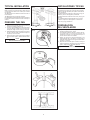
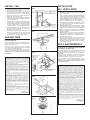
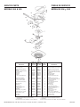
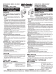
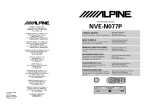
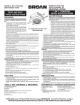
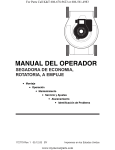
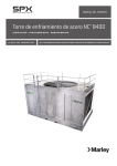
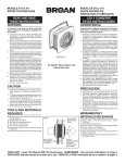
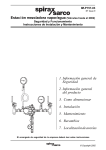
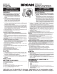
MODELOS 504 Y 505 VENTILADORES DE DESCARGA VERTICAL MODELS 504 & 505 VERTICAL DISCHARGE FANS READ AND SAVE THESE INSTRUCTIONS LEA Y CONSERVE ESTAS INSTRUCCIONES WARNING ADVERTENCIA PARA REDUCIR EL RIESGO DE INCENDIO, DESCARGA ELECTRICA, O TO REDUCE THE RISK OF FIRE, ELECTRIC SHOCK, LESIONES PERSONALES, CUMPLA CON LOS SIGUIENTES PUNTOS: OR INJURY TO PERSONS, OBSERVE THE FOLLOW1. Solamente use esta unidad de la manera propuesta por el fabricante. ING: Si tiene alguna pregunta, póngase en contacto con el fabricante en 1. Use this unit only in the manner intended by the la dirección o teléfono anotados en la garantía. manufacturer. If you have questions, contact the 504 2. Antes de limpiar o de poner en servicio la unidad, apague el interruptor manufacturer at the address or telephone number en el panel de servicio, y asegure el panel de servicio para evitar 505 listed in the warranty. que se encienda accidentalmente. Cuando el dispositivo para 2. Before servicing or cleaning unit, switch power desconectar el servicio eléctrico no puede ser cerrado con algún off at service panel and lock the service discontipo de traba, sujete fuertemente al panel de servicio, una etiqueta necting means to prevent power from being de advertencia prominente. To register this product visit switched on accidentally. When the service dis3. El trabajo de instalación y el alambrado eléctrico deben de llevarse www.broan.com connecting means cannot be locked, securely a cabo por personal calificado, de acuerdo con todos los códigos y fasten a prominent warning device, such as a las normas aplicables, incluyendo los códigos y normas de tag, to the service panel. construcción contra incendios. 3. Installation work and electrical wiring must be done by a qualified person(s) in 4. Se requiere una cantidad de aire suficiente para la combustion y escape de gases por accordance with all applicable codes and standards, including fire-rated conla chimenea del equipo que quema combustible para prevenir la retrogresión de la llama. struction codes and standards. Siga las especificaciones y estándares de seguridad para equipos de calefacción del fabricante, tales como los publicados por la Asociación Nacional de Protección Contra 4. Sufficient air is needed for proper combustion and exhausting of gases Incendios (NFPA por sus siglas en inglés), y la Sociedad Americana de Ingenieros de through the flue (chimney) of fuel burning equipment to prevent backdrafting. Calefacción, Refrigeración y Aire Acondicionado (ASHRAE), y los códigos de las Follow the heating equipment manufacturer’s guideline and safety standards autoridades locales. such as those published by the National Fire Protection Association (NFPA), 5. Cuando corte o taladre en una pared o cielo raso, no dañe los cables eléctricos u otras and the American Society for Heating, Refrigeration and Air Conditioning instalaciones no visibles. Engineers (ASHRAE), and the local code authorities. 6. Los ventiladores con ductos deben ser siempre ventilados hacia el exterior. 5. When cutting or drilling into wall or ceiling, do not damage electrical wiring and 7. Si esta unidad va a ser instalada sobre una bañera o ducha,debe ser marcada como other hidden utilities. apropiada para dicha aplicación. 6. Ducted fans must always be vented to the outdoors. 8. Nunca coloque un interruptor donde pueda ser alcanzado desde la bañera o la ducha. 7. If this unit is to be installed over a tub or shower, it must be marked as 9. Esta unidad debe ser conectada a tierra. appropriate for the application. PARA REDUCIR EL RIESGO DE INCENDIO DEBIDO A GRASA ACUMULADA EN LAS 8. Never place a switch where it can be reached from a tub or a shower. HORNILLAS: 9. This unit must be grounded. 1. Nunca deje sin atender las unidades de superficie cuando tengan ajustes altos. Los TO REDUCE THE RISK OF A RANGE TOP GREASE FIRE: reboses pueden provocar humo y derrames grasosos que se pueden incendiar. 1. Never leave surface units unattended at high settings. Boilovers cause smoking Caliente lentamente el aceite en un ajuste bajo o medio. and greasy spillovers that may ignite. Heat oils slowly on low or medium settings. 2. Siempre ENCIENDA la campana cuando cocine con alta temperatura o cuando cocine 2. Always turn hood ON when cooking at high heat or when cooking flaming foods. alimentos que se puedan incendiar. 3. Clean ventilating fans frequently. Grease should not be allowed to accumulate on 3. Limpie con frecuencia los ventiladores. No debe permitir que la grasa se acumule en fan or filter. el ventilador ni en el filtro. 4. Use proper pan size. Always use cookware appropriate for the size of the 4. Utilice un sartén de tamaño adecuado. Siempre utilice el utensilio adecuado al tamaño del elemento de superficie. surface element. PARA REDUCIR EL RIESGO DE LESION A PERSONAS RESULTADO DE UN INCENDIO TO REDUCE THE RISK OF INJURY TO PERSONS IN THE EVENT OF A RANGE TOP DEBIDO A GRASA ACUMULADA EN LAS HORNILLAS, PROCURE LO SIGUIENTE:* GREASE FIRE, OBSERVE THE FOLLOWING:* 1. AHOGUE LAS LLAMAS con una tapa ajustada o charola de metal, después apague la 1. SMOTHER FLAMES with a close-fitting lid, cookie sheet, or metal tray, then turn hornilla. TENGA CUIDADO A FIN DE EVITAR QUEMADURAS. Si las llamas no se apagan off the burner. BE CAREFUL TO PREVENT BURNS. If the flames do not go out de inmediato, EVACUE Y AVISE A LOS BOMBEROS. immediately, EVACUATE AND CALL THE FIRE DEPARTMENT. 2. NO LEVANTE NUNCA UNA SARTEN QUE ESTE EN LLAMAS - Usted se podrá quemar. 2. NEVER PICK UP A FLAMING PAN - You may be burned. 3. NO UTILICE AGUA, incluyendo toallas de cocina mojadas - puede resultar una explosión 3. DO NOT USE WATER, including wet dishcloths or towels - a violent steam explosion de vapor violenta. will result. 4. Utilice un extinguidor SOLAMENTE si: 4. Use an extinguisher ONLY if: A. Usted sabe que tiene un extinguidor de clas ABC y lo sabe utilizar. A. You know you have a Class ABC extinguisher and you already know how to operate B. El incendio es pequeño y contenido dentro del área donde se inició. it. C. Los bomberos han sido avisados. B. The fire is small and contained in the area where it started. D. Usted puede combatir el incendio con una salida a su espalda. C. The fire department is being called. * Basado en las recomendaciones para “Seguridad en la Cocina” publicadas por la NFPA de D. You can fight the fire with your back to an exit. los EEUU. *Based on “Kitchen Firesafety Tips” published by NFPA. PRECAUCION CAUTION 1. For general ventilating use only. Do not use to exhaust hazardous or explosive materials and vapors. 2. This product is designed for ceiling installation only. DO NOT MOUNT THIS PRODUCT IN A WALL! 3. To avoid motor bearing damage and noisy and/or unbalanced impellers, keep drywall spray, construction dust, etc. off power unit. 4. Please read specification label on product for further information and requirements. TOOLS AND MATERIALS REQUIRED Straight blade screwdriver Hammer Pliers Electrical wiring and supplies of type to comply with local code 8” or 10” round duct as required Duct tape, caulk and tin snips Roof cap Saw 1. Solamente para uso de ventilación general. No se use para extraer materiales o vapores peligrosos o explosivos. 2. Este producto está diseñado para intalación en cielo raso. NO INSTALE ESTE PRODUCTO EN UNA PARED! 3. Para evitar daños al cojinete del motor y/o impulsores ruidosos o desequilibrados, mantenga la fuente de potencia lejos de rocíos de yeso, de polvo de construcción, etc. 4. Lea la etiqueta de especificaciones del producto para más información y requisitos. HERRAMIENTAS Y MATERIALES NECESARIOS Destornillador de hoja ancha Martillo Alicates Herramientas eléctricas del tipo necesario para cumplir con los códigos locales. Clavos o tornillos para madera Ducto redondo de 20,32 cm a 25,40 cm (8 o 10 pulg.), transiciones y codos, si es necesario Cinta adhesiva para ductos Cubierta de techo o pared INSTALLER: Leave This Manual With The Homeowner. HOMEOWNER: Use and Care Information on Page 3. INSTALADOR: Deje este manual con el dueño de casa. DUEÑO DE CASA: Información del uso y mantenimiento en la página 3. TYPICAL INSTALLATION FIG. 1 INSTALACIONES TIPICAS 634 OR 644 ROOF CAP CUBIERTA DE TECHO 634 O 644 Fig. 1 shows typical installations. Make sure that the selected location allows enough vertical clearance above the fan to allow you to install the ductwork. The Model 505 uses 8” diameter ductwork and has a built-in damper. The Model 504 uses 10” diameter ductwork. Use the Model 472 Reducer/Damper with the 504 when 8” diameter ductwork is desired or when a damper is needed. Fig. 1 muestra instalaciones típicas. Compruebe que el lugar que se escogió tiene suficiente campo encima del ventilador para permitir la instalación de los conductos. El modelo 505 lleva conductos de 20,32 cm (8 pulg.) de diámetro y tiene un amortiguador preinstalado. El modelo 504 lleva conductos de 25,40 cm (10 pulg.) de diámetro. Use el Reductor/Amortiguador Modelo 472 con el 504 cuando se requiere un amortiguador o conductos de 20,32 cm (8 pulg.) de diámetro OPTIONAL 472 REDUCER/DAMPER AMORTIGUADOR/ REDUCTOR 472 OPCIONAL PREPARE THE FAN 1. Remove motor assembly by loosening mounting screws and rotating motor (FIG. 2). 2. Use care when handling motor bracket assembly to prevent damage to blade. Do not set down assembly with weight of motor resting on the blade. 3. Slide adjustable mounting brackets into channels on side of housing (FIG. 3). Brackets expand to fit joists up to 24” on center. 4. Remove knockout from wiring box by breaking tabs on knockout (FIG. 4). Remove bottom knockout. NOTE Remove bottom knockout ONLY! 505 504 PREPARACION DEL VENTILADOR 1. Saque el conjunto del motor aflojando los tornillos de montaje y girando el motor. (FIG. 2) 2. Use especial cuidado al manejar el conjunto del motor prevenir daño a la hélice del ventilador. No establezca al conjunto con el peso del motor que se reclina sobre la hélice del ventilador. 3. Deslice los soportes de montaje ajustables en los canales laterales de la caja (FIG. 3). Los soportes se expanden hasta ajustarse en las vigas hasta 60,96 cm (24 pulg.) en el centro. 4. Saque el disco removible para el cable de la caja de cables rompiendo las lengüetas en el disco removible (FIG. 4). Saque el disco removible del fondo. NOTA Saque SOLAMENTE el disco removible del fondo. FIG. 2 FIG. 3 FIG. 4 FIG. 5 2 INSTALL FAN 1. Place fan in installation location. Extend adjustable brackets to fit joists (FIG. 5). 2. Nail or screw brackets to joists so that flange on housing will flush with finished ceiling (FIG. 6). For wide joist centers: A #8 x 3/8 self-tapping screw can be used to join extended brackets together and create a rigid mount. 3. Slide fan to either side for final positioning. Crimp bracket channels with pliers to keep fan from shifting to one side (FIG. 7). 4. Connect cable to wiring box with proper cable connector for type of cable used. Provide 6” leads inside box. Make electrical connections as shown in Figure 8. Make sure unit is grounded using green ground screw. Install wiring box and cover. 5. Install ductwork and roof cap. Check both fan damper and damper inside roof cap to make sure that they open freely (FIG. 9). 6. Reinstall motor assembly. Spin fan blade by hand to make sure that blade does not strike anything in housing. Plug in motor, turn on power and check operation of fan. Install grille (FIG. 10). INSTALACION DEL VENTILADOR FIG. 6 1. Coloque el ventilador en la posición de instalación. Extienda los soportes ajustables hasta que se ajusten en las vigas (FIG. 5). 2. Clave o atornille los soportes a las vigas de manera que el borde de la caja esté a nivel con el cielo raso acabado (FIG. 6). En caso de centro de vigas anchos: un tornillo autoenroscable #8 x 3/8 se puede usar para unir los soportes extendidas y crear una montura rígida. 3. Deslice el ventilador hacia uno de los lados para su posicionamiento final. Doble los canales de los soportes con el alicates para evitar que el ventilador se mueva de un lado a otro (FIG. 7). 4. Conecte el cable a la caja de cables usando el conector apropiado para el tipo de cable que se esté usando. Haga conexiones eléctricas tal como se muestra en la figura 8. Compruebe que la unidad está conectada a tierra con el tornillo verde de tierra. Instale la caja de cables y la cubierta. 5. Instale los ductos y la cubierta del cielo raso. Revise el amortiguador del ventilador y el amortiguador adentro de la cubierta del cielo raso para comprobar de que se abren libremente (FIG. 9). 6. Vuelva a instalar el conjunto del motor. Gire la hélice con la mano para comprobar que ésta no golpea contra ninguna parte de la caja. Enchufe el motor, conecte la corriente y compruebe el funcionamiento del ventilador. Instale la rejilla (FIG. 10). FIG. 7 USE AND CARE DISCONNECT ELECTRICAL POWER SUPPLY BEFORE SERVICING FAN. Always unplug the fan motor before servicing the fan. The motor bearings on this fan are lifetime lubricated and will never need oiling. Clean the fan blade and motor every six months by removing the grille, unplugging the motor, and gently vacuuming the fan blade and motor. Clean the grille in warm, soapy water. Use a mild detergent, such as a dishwashing liquid. DO NOT USE ABRASIVE CLOTHS, STEEL WOOL OR SCOURING POWDERS. BROAN-NUTONE ONE YEAR LIMITED WARRANTY Broan-NuTone warrants to the original consumer purchaser of its products that such products will be free from defects in materials or workmanship for a period of one year from the date of original purchase. THERE ARE NO OTHER WARRANTIES, EXPRESS OR IMPLIED, INCLUDING, BUT NOT LIMITED TO, IMPLIED WARRANTIES OF MERCHANTABILITY OR FITNESS FOR A PARTICULAR PURPOSE. During this one-year period, Broan-NuTone will, at its option, repair or replace, without charge, any product or part which is found to be defective under normal use and service. THIS WARRANTY DOES NOT EXTEND TO FLUORESCENT LAMP STARTERS AND TUBES. This warranty does not cover (a) normal maintenance and service or (b) any products or parts which have been subject to misuse, negligence, accident, improper maintenance or repair (other than by Broan-NuTone), faulty installation or installation contrary to recommended installation instructions. The duration of an implied warranty is limited to the one-year period as specified for the express warranty. Some states do not allow limitation on how long an implied warranty lasts, so the above limitation may not apply to you. BROAN-NUTONE’S OBLIGATION TO REPAIR OR REPLACE, AT BROAN-NUTONE’S OPTION, SHALL BE THE PURCHASER’S SOLE AND EXCLUSIVE REMEDY UNDER THIS WARRANTY. BROAN-NUTONE SHALL NOT BE LIABLE FOR INCIDENTAL, CONSEQUENTIAL OR SPECIAL DAMAGES ARISING OUT OF OR IN CONNECTION WITH PRODUCT USE OR PERFORMANCE. Some states do not allow the exclusion or limitation of incidental or consequential damages, so the above limitation may not apply to you. This warranty gives you specific legal rights, and you may also have other rights, which vary from state to state. This warranty supersedes all prior warranties. To qualify for warranty service, you must (a) notify Broan-NuTone at the address stated below or telephone: 1-800-637-1453, (b) give the model number and part identification and (c) describe the nature of any defect in the product or part. At the time of requesting warranty service, you must present evidence of the original purchase date. Broan-NuTone LLC 926 West State Street, Hartford, WI 53027 USO Y MANTENIMIENTO FIG. 8 BLACK NEGRO GROUND (BARE OR GREEN WIRE) TIERRA (CABLE VERDE O DESCUBIERTO) BLACK NEGRO DESCONECTE LA CORRIENTE ELECTRICA ANTES DE DAR SERVICIO AL VENTILADOR. Desconecte siempre el motor del ventilador antes de dar servicio al ventilador. Los cojinetes del motor en este ventilador están lubricados de por vida y nunca necesitarán lubricación. Limpie la hélice del ventilador y el motor cada seis meses sacando la rejilla, desconectando el motor, y limpiando suavemente la hélice y el motor con una aspiradora. Limpie la rejilla en agua caliente enjabonada. Use un detergente suave, tal como líquido lavavajillas. NO USE TELAS ÁSPERAS, ESPONJILLAS DE LANA DE ACERO O POLVOS ÁSPEROS. WHITE BLANKO BLACK NEGRO WHT BLANCO GROUND (BARE OR GREEN WIRE) TIERRA (CABLE VERDE O DESCUBIERTO) FIG. 9 FIG. 10 3 GARANTIA BROAN-NUTONE LIMITADA POR UN AÑO Broan-NuTone garantiza al consumidor comprador original de sus productos que dichos productos carecerán de defectos en materiales o en mano de obra por un período de un año a partir de la fecha original de compra. NO EXISTEN OTRAS GARANTIAS, EXPLICITAS O IMPLICITAS, INCLUYENDO, PERO NO LIMITADAS A, GARANTIAS IMPLICITAS DE COMERCIALIZACION O APTITUD PARA UN PROPOSITO PARTICULAR. Durante el período de un año, y a su propio criterio, Broan-NuTone reparará o reemplazará, sin costo alguno cualquier producto o pieza que se encuentre defectuosa bajo condiciones normales de servicio y uso. ESTA GARANTIA NO SE APLICA A TUBOS Y ARRANCADORES DE LAMPARAS FLUORESCENTES. Esta garantía no cubre (a) mantenimiento y servicio normales o (b) cualquier producto o piezas que hayan sido utilizadas de forma errónea, negligente, que hayan causado un accidente, o que hayan sido reparadas o mantenidas inapropiadamente (por otras compañías que no sean Broan-NuTone), instalación defectuosa, o instalación contraria a las instrucciones de instalación recomendadas. La duración de cualquier garantía implícita se limita a un período de un año como se especifica en la garantía expresa. Algunos estados no permiten limitaciones en cuanto al tiempo de expiración de una garantía implícita, por lo que la limitación antes mencionada puede no aplicarse a usted. LA OBLIGACION DE BROAN-NUTONE DE REPARAR O REEMPLAZAR, SIGUIENDO EL CRITERIO DE BROAN-NUTONE, DEBERA SER EL UNICO Y EXCLUSIVO RECURSO LEGAL DEL COMPRADOR BAJO ESTA GARANTIA. BROAN-NUTONE NO SERA RESPONSABLE POR DAÑOS INCIDENTALES, CONSIGUIENTES, O POR DAÑOS ESPECIALES QUE SURJAN A RAIZ DEL USO O DESEMPEÑO DEL PRODUCTO. Algunos estados no permiten la exclusión o limitación de daños incidentales o consiguientes, por lo que la limitación antes mencionada puede no aplicarse a usted. Esta garantía le proporciona derechos legales específicos, y usted puede también tener otros derechos, los cuales varían de estado a estado. Esta garantía reemplaza todas las garantías anteriores. Para calificar en la garantía de servicio, usted debe (a) notificar a BroanNuTone al domicilio que se menciona abajo o al teléfono:1-800-637-1453, (b) dar el número del modelo y la identificación de la pieza, y (c) describir la naturaleza de cualquier defecto en el producto o pieza. En el momento de solicitar servicio cubierto por la garantía, usted debe de presentar evidencia de la fecha original de compra. Broan-NuTone LLC 926 West State Street, Hartford, WI 53027 EE. UU. SERVICE PARTS PIEZAS DE SERVICIO MODELS 504 & 505 MODELOS 504 y 505 20 21 19 18 17 16 (505) (504) 23 22 15 DESCRIPTION Damper Rod Damper Leaf (2 Req.) Damper Rod Bushing (2 Req.) Housing #8B x 3/8 Hex Head Self Tapping Screws (2 Req.)* Receptacle Fan Blade Fan Motor ¼-20 U-Type Sheet Metal Nut KEY NO. MODEL 504 MODEL 505 PART NO. PART NO. MODELO 504 MODELO 505 NO. PIEZ NO. PIEZ NO. CODIGO 1 2 3 4 5 ——— ——— ——— 97007080 99170245 98009485 98006062 99100379 97007077 99170245 1 2 3 4 5 6 7 8 9 99270982 99020271 99080596 99260434 99270982 99020165 99080176 99260434 6 7 8 9 Motor Mounting Bracket #8-32 x 1/2 Hex Head Self Tapping Screws (2 Req.) * 10 11 98006066 99150479 98007820 99150479 10 11 Motor Mounting Nuts (2 Req.) 12 99260425 99260428 12 Grille (Polymeric) Grille Knob Wiring Box Cover #10-32 x 1/2 Hex Head Self Tapping Screw Wiring Box Support Angle - long (4 Req.) 13 15 16 17 99110977 97011918 98006047 99150471 99110916 97011918 98006047 99150471 13 15 16 17 18 19 98006046 98003036 98006046 98003036 18 19 PH HD Screw, #10-12 x .625 Damper Bumper (2 Req.) Grille Stud Grille Bracket 20 21 22 23 99150591 ——— 99420580 98008494 99150591 99100380 99420585 98008494 20 21 22 23 Standard Hardware. May be purchased locally. ** Not Illustrated. Order replacement parts by "PART NO." - NOT by "KEY NO." * DESCRIPCION Eje del amortiguador Hoja del amortiguador (se necesitan 2) Casquillo del eje del amortiguador Caja Tornillos autoenroscables de cabeza hexagonal #8B x 3/8 (se necesitan 2)* Receptáculo Hélice del ventilador Motor del ventilador Tuerca de hoja de metal ¼-20 de tipo U Soporte de montaje del motor Tornillos autoenroscables de cabeza hexagonal #8-32 x 1/2 (se necesitan 2)* Tuercas de montaje del motor (se necesitan 2) Rejilla (plástico) Botón de la rejilla Cubierta de la caja de cables Tornillo autoenroscables de cabeza hexagonal #10-32 x 1/2 Caja de cables Ángulo de soporte - largo (se necesitan 4) Tornillo, #10-12 x .625 PH HD Tope del amortiguador (se necesitan 2) Tornillo de la rejilla Ménsula de la rejilla * Material estándar. Puede ser adquirido localmente. ** No ilustrado. Encargue piezas de servicio por "NO. PIEZ" - NO por "NO. CODIGO". Broan-NuTone LLC • 926 West State Street • Hartford, WI 53027 • (1-800-637-1453) 99042342L