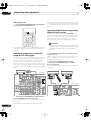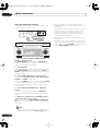
1
VSX-54TX_0430.book 1 ページ 2004年5月6日 木曜日 午後8時7分
AUDIO/VIDEO MULTI-CHANNEL
RECEIVER
VSX-54TX
Register your product at
www.pioneerelectronics.com
• Protect your new investment
The details of your purchase will be on file for reference in the event of an
insurance claim such as loss or theft.
• Receive free tips, updates and service bulletins on
your new product
• Improve product development
Your input helps us continue to design products that meet your needs.
• Receive a free Pioneer newsletter
Registered customers can opt in to receive a monthly newsletter.
Operating Instructions
VSX-54TX_0430.book 2 ページ 2004年5月6日 木曜日 午後8時7分
CAUTION
RISK OF ELECTRIC SHOCK
DO NOT OPEN
The lightning flash with arrowhead, within
an equilateral triangle, is intended to alert
the user to the presence of uninsulated
"dangerous voltage" within the product's
enclosure that may be of sufficient
magnitude to constitute a risk of electric
shock to persons.
CAUTION:
TO PREVENT THE RISK OF ELECTRIC
SHOCK, DO NOT REMOVE COVER (OR
BACK). NO USER-SERVICEABLE PARTS
INSIDE. REFER SERVICING TO QUALIFIED
SERVICE PERSONNEL.
The exclamation point within an equilateral
triangle is intended to alert the user to the
presence of important operating and
maintenance (servicing) instructions in the
literature accompanying the appliance.
D1-4-2-3_En
Thank you for buying this Pioneer product.
Please read through these operating
instructions so you will know how to
operate your model properly. After you have
finished reading the instructions, put them
away in a safe place for future reference.
WARNING: Handling the cord on this product or
cords associated with accessories sold with the
product will expose you to lead, a chemical known to
the State of California and other governmental
entities to cause cancer and birth defects or other
reproductive harm.
D36-P4_En
Wash hands after handling
CAUTION
– TO PREVENT ELECTRIC SHOCK DO
NOT USE THIS (POLARIZED) PLUG
WITH AN EXTENSION CORD.
RECEPTACLE OR OTHER OUTLET
UNLESS THE BLADES CAN BE
FULLY INSERTED TO PREVENT
BLADE EXPOSURE.
ATTENTION – POUR PREVENIR LES CHOCS
ELECTRIQUES, NE PAS UTILISER
CETTE FICHE POLARISEE AVEC UN
PROLONGATEUR, UNE PRISE DE
COURANT, OU UNE AUTRE SORTIE
DE COURANT, SAUF SI LES LAMES
PEUVENT ETRE INSEREES A FOND
SANS EN LAISSER AUCUNE PARTIE
D2-4-4-1_EF
A DECOUVERT.
WARNING – TO PREVENT FIRE OR SHOCK
HAZARD, DO NOT EXPOSE THIS
APPLIANCE TO RAIN OR MOISTURE.
D1-4-2-1_En
IMPORTANT NOTICE – THE SERIAL NUMBER FOR THIS EQUIPMENT IS LOCATED IN THE REAR.
PLEASE WRITE THIS SERIAL NUMBER ON YOUR ENCLOSED WARRANTY CARD AND
D1-4-2-6-1_En
KEEP IN A SECURE AREA. THIS IS FOR YOUR SECURITY.
This Class B digital apparatus complies with Canadian ICES-003.
Cet appareil numérique de la Classe B est conforme à la norme NMB-003 du Canada.
D8-10-1-3_EF
Information to User
Alteration or modifications carried out without appropriate authorization may invalidate the user’s right to operate
D8-10-2_En
the equipment.
NOTE: This equipment has been tested and found to comply with the limits for a Class B digital device, pursuant to
Part 15 of the FCC Rules. These limits are designed to provide reasonable protection against harmful interference in
a residential installation. This equipment generates, uses, and can radiate radio frequency energy and, if not
installed and used in accordance with the instructions, may cause harmful interference to radio communications.
However, there is no guarantee that interference will not occur in a particular installation. If this equipment does
cause harmful interference to radio or television reception, which can be determined by turning the equipment off
and on, the user is encouraged to try to correct the interference by one or more of the following measures:
–
–
–
–
Reorient or relocate the receiving antenna.
Increase the separation between the equipment and receiver.
Connect the equipment into an outlet on a circuit different from that to which the receiver is connected.
D8-10-1-2_En
Consult the dealer or an experienced radio/TV technician for help.
CAUTION: This product satisfies FCC regulations when shielded cables and connectors are used to connect the
unit to other equipment. To prevent electromagnetic interference with electric appliances such as radios and
D8-10-3a_En
televisions, use shielded cables and connectors for connections.
VSX-54TX_0430.book 3 ページ 2004年5月6日 木曜日 午後8時7分
IMPORTANT SAFETY INSTRUCTIONS
READ INSTRUCTIONS — All the safety and
operating instructions should be read before the
product is operated.
RETAIN INSTRUCTIONS — The safety and
operating instructions should be retained for
future reference.
HEED WARNINGS — All warnings on the product
and in the operating instructions should be
adhered to.
FOLLOW INSTRUCTIONS — All operating and use
instructions should be followed.
CLEANING — The product should be cleaned only
with a polishing cloth or a soft dry cloth. Never
clean with furniture wax, benzine, insecticides
or other volatile liquids since they may corrode
the cabinet.
ATTACHMENTS — Do not use attachments not
recommended by the product manufacturer as
they may cause hazards.
WATER AND MOISTURE — Do not use this
product near water — for example, near a
bathtub, wash bowl, kitchen sink, or laundry
tub; in a wet basement; or near a swimming
pool; and the like.
ACCESSORIES — Do not place this product on an
unstable cart, stand, tripod, bracket, or table.
The product may fall, causing serious injury to a
child or adult, and serious damage to the
product. Use only with a cart, stand, tripod,
bracket, or table recommended by the
manufacturer, or sold with the product. Any
mounting of the product should follow the
manufacturer’s instructions, and should use a
mounting accessory recommended by the
manufacturer.
CART — A product and cart combination should be
moved with care. Quick stops, excessive force,
and uneven surfaces may cause the product
and cart combination to overturn.
VENTILATION — Slots and openings in the cabinet
are provided for ventilation and to ensure
reliable operation of the product and to protect
it from overheating, and these openings must
not be blocked or covered. The openings should
never be blocked by placing the product on a
bed, sofa, rug, or other similar surface. This
product should not be placed in a built-in
installation such as a bookcase or rack unless
proper ventilation is provided or the
manufacturer’s instructions have been adhered
to.
POWER SOURCES — This product should be
operated only from the type of power source
indicated on the marking label. If you are not
sure of the type of power supply to your home,
consult your product dealer or local power
company.
LOCATION – The appliance should be installed in a
stable location.
NONUSE PERIODS – The power cord of the
appliance should be unplugged from the outlet
when left un-used for a long period of time.
GROUNDING OR POLARIZATION
• If this product is equipped with a polarized
alternating current line plug (a plug having one
blade wider than the other), it will fit into the
outlet only one way. This is a safety feature. If
you are unable to insert the plug fully into the
outlet, try reversing the plug. If the plug should
still fail to fit, contact your electrician to replace
your obsolete outlet. Do not defeat the safety
purpose of the polarized plug.
• If this product is equipped with a three-wire
grounding type plug, a plug having a third
(grounding) pin, it will only fit into a grounding
type power outlet. This is a safety feature. If you
are unable to insert the plug into the outlet,
contact your electrician to replace your obsolete
outlet. Do not defeat the safety purpose of the
grounding type plug.
POWER-CORD PROTECTION — Power-supply
cords should be routed so that they are not likely
to be walked on or pinched by items placed
upon or against them, paying particular
attention to cords at plugs, convenience
receptacles, and the point where they exit from
the product.
OUTDOOR ANTENNA GROUNDING — If an
outside antenna or cable system is connected to
the product, be sure the antenna or cable
system is grounded so as to provide some
protection against voltage surges and built-up
static charges. Article 810 of the National
Electrical Code, ANSI/NFPA 70, provides
information with regard to proper grounding of
the mast and supporting structure, grounding of
the lead-in wire to an antenna discharge unit,
size of grounding conductors, location of
antenna-discharge unit, connection to
grounding electrodes, and requirements for the
grounding electrode. See Figure A.
LIGHTNING — For added protection for this
product during a lightning storm, or when it is
left unattended and unused for long periods of
time, unplug it from the wall outlet and
disconnect the antenna or cable system. This
will prevent damage to the product due to
lightning and power-line surges.
POWER LINES — An outside antenna system
should not be located in the vicinity of overhead
power lines or other electric light or power
circuits, or where it can fall into such power
lines or circuits. When installing an outside
antenna system, extreme care should be taken
to keep from touching such power lines or
circuits as contact with them might be fatal.
OVERLOADING — Do not overload wall outlets,
extension cords, or integral convenience
receptacles as this can result in a risk of fire or
electric shock.
OBJECT AND LIQUID ENTRY — Never push
objects of any kind into this product through
openings as they may touch dangerous voltage
points or short-out parts that could result in a
fire or electric shock. Never spill liquid of any
kind on the product.
SERVICING — Do not attempt to service this
product yourself as opening or removing covers
may expose you to dangerous voltage or other
hazards. Refer all servicing to qualified service
personnel.
DAMAGE REQUIRING SERVICE — Unplug this
product from the wall outlet and refer servicing
to qualified service personnel under the
following conditions:
• When the power-supply cord or plug is
damaged.
• If liquid has been spilled, or objects have fallen
into the product.
• If the product has been exposed to rain or water.
• If the product does not operate normally by
following the operating instructions. Adjust only
those controls that are covered by the operating
instructions as an improper adjustment of other
controls may result in damage and will often
require extensive work by a qualified technician
to restore the product to its normal operation.
• If the product has been dropped or damaged in
any way.
• When the product exhibits a distinct change in
performance — this indicates a need for service.
REPLACEMENT PARTS — When replacement parts
are required, be sure the service technician has
used replacement parts specified by the
manufacturer or have the same characteristics
as the original part. Unauthorized substitutions
may result in fire, electric shock, or other
hazards.
SAFETY CHECK — Upon completion of any service
or repairs to this product, ask the service
technician to perform safety checks to
determine that the product is in proper
operating condition.
WALL OR CEILING MOUNTING — The product
should not be mounted to a wall or ceiling.
HEAT — The product should be situated away from
heat sources such as radiators, heat registers,
stoves, or other products (including amplifiers)
that produce heat.
ANTENNA
LEAD IN
WIRE
GROUND
CLAMP
ANTENNA
DISCHARGE UNIT
(NEC SECTION 810-20)
ELECTRIC
SERVICE
EQUIPMENT
Fig. A
GROUNDING CONDUCTORS
(NEC SECTION 810-21)
GROUND CLAMPS
POWER SERVICE GROUNDING
ELECTRODE SYSTEM
(NEC ART 250, PART H)
NEC — NATIONAL ELECTRICAL CODE
D1-4-2-2_En
This product is for general household purposes. Any
failure due to use for other than household purposes
(such as long-term use for business purposes in a
restaurant or use in a car or ship) and which
requires repair will be charged for even during the
K041_En
warranty period.
For U.S. and Australia Model
C67-7-3_En
VSX-54TX_0430.book 4 ページ 2004年5月6日 木曜日 午後8時7分
Contents
01 Before you start
04 Controls and displays
Features . . . . . . . . . . . . . . . . . . . . . . . . . . . . . . . . . . . 6
Checking the supplied accessories . . . . . . . . . . . . . . 6
Ventilation . . . . . . . . . . . . . . . . . . . . . . . . . . . . . . . . . 7
Installing the receiver . . . . . . . . . . . . . . . . . . . . . . . . . 7
Opening the front panel . . . . . . . . . . . . . . . . . . . . . . . 7
Using the remote control . . . . . . . . . . . . . . . . . . . . . . 7
Loading the batteries . . . . . . . . . . . . . . . . . . . . . . . . 7
Operating range of the remote control . . . . . . . . . . . 8
Front panel . . . . . . . . . . . . . . . . . . . . . . . . . . . . . . . . 32
Display . . . . . . . . . . . . . . . . . . . . . . . . . . . . . . . . . . . 34
Remote control . . . . . . . . . . . . . . . . . . . . . . . . . . . . . 35
02 5 minute guide
Introduction to home theater . . . . . . . . . . . . . . . . . . . 9
Setting up for Surround Sound . . . . . . . . . . . . . . . . . . 9
Automatically setting up for surround sound . . . . . . 12
Other problems when using the Auto
Surround Setup . . . . . . . . . . . . . . . . . . . . . . . . . . . 14
Checking the settings on your DVD (or other)
player . . . . . . . . . . . . . . . . . . . . . . . . . . . . . . . . . . . . 14
Playing a source . . . . . . . . . . . . . . . . . . . . . . . . . . . . 14
03 Connecting your equipment
Rear panel . . . . . . . . . . . . . . . . . . . . . . . . . . . . . . . . 15
About the video converter . . . . . . . . . . . . . . . . . . . . . 16
About cable types . . . . . . . . . . . . . . . . . . . . . . . . . . . 17
Analog audio cables . . . . . . . . . . . . . . . . . . . . . . . . 17
Digital audio cables . . . . . . . . . . . . . . . . . . . . . . . . 17
Video cables . . . . . . . . . . . . . . . . . . . . . . . . . . . . . . 17
When making cable connections . . . . . . . . . . . . . . . 17
Connecting your TV . . . . . . . . . . . . . . . . . . . . . . . . . 18
Connecting a DVD player . . . . . . . . . . . . . . . . . . . . . 19
Connecting the multichannel analog outputs . . . . 20
Connecting a satellite/cable receiver or
other set-top box . . . . . . . . . . . . . . . . . . . . . . . . . . . . 21
Connecting a VCR or DVD recorder . . . . . . . . . . . . . 22
Connecting other video sources . . . . . . . . . . . . . . . . 23
Using the component video jacks . . . . . . . . . . . . . . . 24
Connecting digital audio sources . . . . . . . . . . . . . . . 25
Connecting analog audio sources . . . . . . . . . . . . . . 26
Connecting a component to the front panel inputs . . 27
Installing your speaker system . . . . . . . . . . . . . . . . . 28
Connecting the speakers . . . . . . . . . . . . . . . . . . . . 29
Placing the speakers . . . . . . . . . . . . . . . . . . . . . . . 29
Connecting antennas . . . . . . . . . . . . . . . . . . . . . . . . 30
AM loop antenna . . . . . . . . . . . . . . . . . . . . . . . . . . 30
FM wire antenna . . . . . . . . . . . . . . . . . . . . . . . . . . 30
Connecting external antennas . . . . . . . . . . . . . . . . 31
Plugging in the receiver . . . . . . . . . . . . . . . . . . . . . . 31
About the AC outlet . . . . . . . . . . . . . . . . . . . . . . . . 31
4
En
05 Listening to your system
Auto playback . . . . . . . . . . . . . . . . . . . . . . . . . . . . . . 37
Listening in surround sound . . . . . . . . . . . . . . . . . . . 37
The MOVIE listening modes . . . . . . . . . . . . . . . . . . 38
The MUSIC listening modes . . . . . . . . . . . . . . . . . . 38
Dolby Pro Logic IIx Music settings . . . . . . . . . . . . . 39
Adjusting the advanced effect level . . . . . . . . . . . . 39
Listening in stereo . . . . . . . . . . . . . . . . . . . . . . . . . . 40
Listening with headphones . . . . . . . . . . . . . . . . . . . . 40
Using the multichannel analog inputs . . . . . . . . . . . 40
Listening with Acoustic Calibration EQ . . . . . . . . . . . 41
Selecting the input signal type . . . . . . . . . . . . . . . . . 41
Using the surround back channel . . . . . . . . . . . . . . 42
Listening with virtual surround back speakers . . . . . 43
Using the audio scaler for Hi-bit and Hi-sampling . . 43
Using Midnight and Loudness listening . . . . . . . . . . 44
Using the tone control . . . . . . . . . . . . . . . . . . . . . . . 44
Switching the tone control on or off . . . . . . . . . . . . 44
Adjusting the bass and treble . . . . . . . . . . . . . . . . 44
Reducing noise during playback. . . . . . . . . . . . . . . . 45
Listening to dual mono soundtracks. . . . . . . . . . . . . 45
06 Using the tuner
Finding a station. . . . . . . . . . . . . . . . . . . . . . . . . . . . 46
Tuning directly to a station . . . . . . . . . . . . . . . . . . . . 46
MPX mode . . . . . . . . . . . . . . . . . . . . . . . . . . . . . . . 46
Memorizing station presets . . . . . . . . . . . . . . . . . . . 47
Listening to memorized station presets . . . . . . . . . 47
Naming station presets . . . . . . . . . . . . . . . . . . . . . 47
07 The Surround Setup menu
Making receiver settings from the Surround
Setup menu . . . . . . . . . . . . . . . . . . . . . . . . . . . . . . . 49
Surround back speaker setting . . . . . . . . . . . . . . . . . 50
Normal surround setting . . . . . . . . . . . . . . . . . . . . . 50
Speaker Setting . . . . . . . . . . . . . . . . . . . . . . . . . . . 50
Channel Level. . . . . . . . . . . . . . . . . . . . . . . . . . . . . 51
Speaker Distance . . . . . . . . . . . . . . . . . . . . . . . . . . 52
VSX-54TX_0430.book 5 ページ 2004年5月6日 木曜日 午後8時7分
08 Controlling other equipment
Using the remote control with other components . . 53
Recalling preset codes . . . . . . . . . . . . . . . . . . . . . . 53
Programming signals from other remote controls . . 54
Controls for TVs . . . . . . . . . . . . . . . . . . . . . . . . . . . . 55
Controls for other components . . . . . . . . . . . . . . . . 56
Direct function . . . . . . . . . . . . . . . . . . . . . . . . . . . . . 58
Multi Operation and System off . . . . . . . . . . . . . . . . 58
Programming a multi-operation . . . . . . . . . . . . . . 58
Using multi operations . . . . . . . . . . . . . . . . . . . . . 59
Programming a shutdown sequence . . . . . . . . . . . 59
Using System off . . . . . . . . . . . . . . . . . . . . . . . . . . 60
Switching components on and off using the 12 volt
trigger . . . . . . . . . . . . . . . . . . . . . . . . . . . . . . . . . . . 60
Operating other Pioneer components with this unit's
sensor . . . . . . . . . . . . . . . . . . . . . . . . . . . . . . . . . . . 60
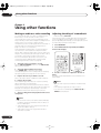
09 Using other functions
Making an audio or a video recording . . . . . . . . . . .
Adjusting the delay of a soundtrack . . . . . . . . . . . . .
Watching video and audio sources independently . .
Dimming the display . . . . . . . . . . . . . . . . . . . . . . . .
Switching the speaker impedance . . . . . . . . . . . . . .
Resetting remote control . . . . . . . . . . . . . . . . . . . . .
Clearing multi operations . . . . . . . . . . . . . . . . . . .
Clearing learned remote control commands . . . . .
Clearing all remote control settings . . . . . . . . . . . .
Resetting the system . . . . . . . . . . . . . . . . . . . . . . . .
62
62
63
63
63
64
64
64
64
64
The Expert setup menu . . . . . . . . . . . . . . . . . . . . . .
Crossover Network . . . . . . . . . . . . . . . . . . . . . . . .
Fine Channel Level . . . . . . . . . . . . . . . . . . . . . . . .
Fine Channel Delay . . . . . . . . . . . . . . . . . . . . . . . .
Acoustic Calibration EQ . . . . . . . . . . . . . . . . . . . .
Professional Acoustic Calibration . . . . . . . . . . . . .
Using Professional Acoustic Calibration . . . . . . . .
Bass Peak Level . . . . . . . . . . . . . . . . . . . . . . . . . .
Dynamic Range Control . . . . . . . . . . . . . . . . . . . .
75
76
76
76
77
79
80
82
83
12 Additional information
Troubleshooting . . . . . . . . . . . . . . . . . . . . . . . . . . . .
Power . . . . . . . . . . . . . . . . . . . . . . . . . . . . . . . . . .
No sound . . . . . . . . . . . . . . . . . . . . . . . . . . . . . . .
Other audio problems . . . . . . . . . . . . . . . . . . . . . .
Video . . . . . . . . . . . . . . . . . . . . . . . . . . . . . . . . . . .
Settings . . . . . . . . . . . . . . . . . . . . . . . . . . . . . . . . .
Display . . . . . . . . . . . . . . . . . . . . . . . . . . . . . . . . .
Remote control . . . . . . . . . . . . . . . . . . . . . . . . . . .
Surround sound formats . . . . . . . . . . . . . . . . . . . . .
Dolby. . . . . . . . . . . . . . . . . . . . . . . . . . . . . . . . . . .
DTS . . . . . . . . . . . . . . . . . . . . . . . . . . . . . . . . . . . .
About THX ®
................................
Preset code brands . . . . . . . . . . . . . . . . . . . . . . . . .
Specifications . . . . . . . . . . . . . . . . . . . . . . . . . . . . .
Maintenance of external surfaces . . . . . . . . . . . . . .
84
84
85
86
87
88
88
89
90
90
90
91
92
93
93
10 Other connections
Second Zone speaker B setup . . . . . . . . . . . . . . . . .
Switching the speaker system . . . . . . . . . . . . . . . .
Bi-amping your front speakers . . . . . . . . . . . . . . . . .
Bi-wiring your speakers . . . . . . . . . . . . . . . . . . . . . .
Multi-room listening . . . . . . . . . . . . . . . . . . . . . . . .
Making multi-room connections . . . . . . . . . . . . . .
Using the multi-room controls . . . . . . . . . . . . . . . .
Connecting an IR receiver . . . . . . . . . . . . . . . . . . . .
Connecting additional amplifiers . . . . . . . . . . . . . . .
Connecting a PC for Advanced MCACC output . . . .
Advanced MCACC output using your PC . . . . . . . .
65
65
66
66
67
67
68
69
69
70
70
11 Advanced setup
The System Setup menu . . . . . . . . . . . . . . . . . . . . .
THX CINEMA Setup . . . . . . . . . . . . . . . . . . . . . . . .
The Input Assign menu . . . . . . . . . . . . . . . . . . . . .
Function Rename . . . . . . . . . . . . . . . . . . . . . . . . .
Multi-Room and IR receiver setup . . . . . . . . . . . . .
12 Volt Trigger . . . . . . . . . . . . . . . . . . . . . . . . . . . .
71
71
72
73
74
74
5
En
VSX-54TX_0430.book 6 ページ 2004年5月6日 木曜日 午後8時7分
01
Before you start
Chapter 1
Before you start
Features
• Easy setup using Advanced Multichannel
Acoustic Calibration (MCACC)
Setting up for home theater sound is as easy as
connecting your speakers, a DVD player or other source,
and your TV. The Auto Surround Setup provides a quick
but accurate surround sound setup, while for complete
surround sound control you still have access to the full
range of surround sound settings.
In addition, the Professional Acoustic Calibration setup
measures the reverb characteristics of your listening
area, allowing you to customize your system calibration
with the help of a graphical output that can be displayed
on-screen, or using a computer.
• Dolby Digital and DTS decoding, including Dolby
Digital EX, DTS 96/24 and DTS-ES
Dolby Digital and DTS decoding brings theater sound
right into your home with up to six channels of surround
sound, including a special LFE (Low Frequency Effects)
channel for deep, realistic sound effects.
The built-in Dolby Pro Logic IIx and DTS Neo:6 decoders
not only provide full surround sound decoding for Dolby
Surround sources, but will also generate convincing
surround sound for any stereo source.
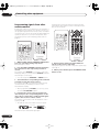
Checking the supplied accessories
Please check that you've received the following supplied
accessories:
• Setup microphone and stand
• Remote control unit
• Alkaline batteries (AA IEC LR6) x 2
• AM loop antenna
Also, with the addition of a surround back speaker, you
can take advantage of the built-in Dolby Digital EX and
DTS-ES decoders for six-channel surround sound.
• Seamless video conversion
With the Pioneer video converter, you can use a wide
range of cables interchangeably, giving you more
flexibility when making video connections.
• Fine-tuned to world-class standards
With the cooperation of the world-class studio engineers
at AIR Studios, this receiver amplifier has been
designated AIR Studios Monitor.
6
En
• FM wire antenna
• These operating instructions
• Warranty card
VSX-54TX_0430.book 7 ページ 2004年5月6日 木曜日 午後8時7分
Before you start
01
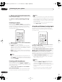
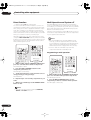
Ventilation
Using the remote control
When installing this unit, make sure to leave space
around the unit for ventilation to improve heat dispersal
(at least 8 in. (20 cm) at the top). If not enough space is
provided between the unit and walls or other equipment,
heat will build up inside, interfering with performance
and/or causing malfunctions.
Receiver
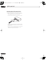
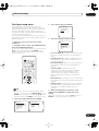
Loading the batteries
Load the batteries into the remote control as shown
below using alkaline batteries (AA IEC LR6) batteries.
When you notice a decrease in the operating range,
replace all batteries with new ones.
8 inches
(20 cm)
Slot and openings in the cabinet are provided for
ventilation and to protect the equipment from
overheating. To prevent fire hazard, do not place anything
on top of the unit, make sure the openings are never
blocked or covered with items (such as newspapers,
table-cloths and curtains), and do not operate the
equipment on thick carpet or a bed.
Installing the receiver
• When installing this unit, make sure to put it on a
level and stable surface.
Don’t install it on the following places:
– on a color TV (the screen may distort)
– near a cassette deck (or close to a device that gives off
a magnetic field). This may interfere with the sound.
– in direct sunlight
– in damp or wet areas
– in extremely hot or cold areas
– in places where there is vibration or other movement
– in places that are very dusty
– in places that have hot fumes or oils (such as a kitchen)
Opening the front panel
To open the front panel, push gently on the lower third of
the panel with your finger.
Caution
Incorrect use of batteries can result in hazards such as
leakage and bursting. Please observe the following:
• Don’t mix new and old batteries together.
• Don’t use different kinds of batteries together—
although they may look similar, different batteries
may have different voltages.
• Make sure that the plus and minus ends of each
battery match the indications in the battery compartment.
• Remove batteries from equipment that isn’t going to
be used for a month or more.
• When disposing of used batteries, please comply
with governmental regulations or environmental
public instruction’s rules that apply in your country or
area.
H048 En
7
En
VSX-54TX_0430.book 8 ページ 2004年5月6日 木曜日 午後8時7分
01
Before you start
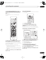
Operating range of the remote control
The operating range is quite large, but please keep in
mind the following when using the remote control:
• Make sure that there are no obstacles between the
remote and the remote sensor on the unit.
• The remote has a range of about 23 feet (7 meters).
30
30
23 feet (7m)
• Remote operation may become unreliable if strong
sunlight or fluorescent light is shining on the unit’s
remote sensor.
• Remote controllers for different devices can interfere
with each other. Avoid using remotes for other
equipment located close to this unit.
8
En
VSX-54TX_0430.book 9 ページ 2004年5月6日 木曜日 午後8時7分
5 minute guide
02
Chapter 2:
5 minute guide
Introduction to home theater
You are probably used to using stereo equipment to listen to music, but may not be used to home theater systems that
give you many more options (such as surround sound) when listening to soundtracks.
Home theater refers to the use of multiple audio tracks to create a surround sound effect, making you feel like you're
in the middle of the action or concert. The surround sound you get from a home theater system depends not only on
the speakers you have set up in your room, but also on the source and the sound settings of the receiver.
DVD-Video has become the basic source material for home theater due to its size, quality, and ease of use. Depending
on the DVD, you can have up to seven different audio tracks coming from one disc, all of them being sent to different
speakers in your system. This is what creates a surround sound effect and gives you the feeling of ‘being there’.
This receiver will automatically decode Dolby Digital, DTS, or Dolby Surround DVD-Video discs, according to your
speaker setup. In most cases, you won’t have to make changes for realistic surround sound, but other possibilities (like
listening to a CD with multichannel surround sound) are explained in Listening to your system on page 37.
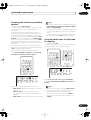
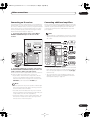
Setting up for Surround Sound
This receiver was designed with the easiest possible setup in mind, so with the following quick setup guide, you should
have your system hooked up for surround sound in no time at all. In most cases, you can simply leave the receiver in
the default settings.
Be sure to complete all connections before connecting this unit to the AC power source.
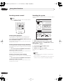
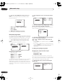
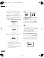
1 Hook up your DVD player.
For surround sound, you’ll want to hook up using a digital connection from the DVD player to the receiver. You can do
this with either a coaxial, or an optical connection (you don’t need to connect both). If you hook up using an optical
cable, you should refer to The Input Assign menu on page 72 to assign the optical input to DVD/LD.
Use a standard RCA video cable to connect your DVD player video output to the receiver using the jacks shown below.
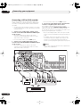
2 Hook up your TV.
Use a standard RCA video cable to connect your receiver to the TV using the jacks as shown below.
Optical cable
VIDEO IN
TV
Standard RCA
video cable
Coaxial digital
audio cable
DIGITAL OUT
14
CE
DVD player
VIDEO OUT
Standard RCA video cable
9
En
VSX-54TX_0430.book 10 ページ 2004年5月6日 木曜日 午後8時7分
02
5 minute guide
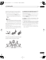
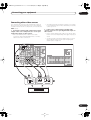
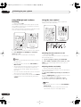
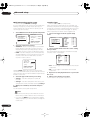
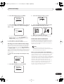
3 Connect your speakers.
To take full advantage of the receiver’s surround sound capabilities connect front, center, surround and surround back
speakers, as well as a subwoofer. Although this is ideal, other configurations with fewer speakers—no subwoofer or
no center speaker, or even no surround speakers—will work. At the very least, front left and right speakers only are
necessary. Note that your main surround speakers should always be connected as a pair, but you can connect just
one surround back speaker if you like (it must be connected to the left surround back terminal).
You can use speakers with a nominal impedance between 6–16 Ω (please see Switching the speaker impedance on
page 63 if you plan to use speakers with an impedance of less than 8 Ω).
Front
right
Front
left
Subwoofer
Center
LINE LEVEL
INPUT
VSX-54TX
Surround
left
10
En
Surround
back left
Surround
back right
Surround
right
VSX-54TX_0430.book 11 ページ 2004年5月6日 木曜日 午後8時7分
5 minute guide
02
Each speaker connection on the receiver comprises a
positive (+) red, and negative (–) black terminal. For
proper sound you should take care to match these up
with the terminals on the speakers themselves.
• If you only have one surround back speaker, hook it
up to the surround back left (Single) terminal.
• If you’re not using a subwoofer, change the front
speaker setting (see Speaker Setting on page 50) to
LARGE.
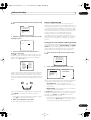
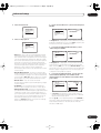
Caution
• Make sure that all the bare speaker wire is twisted
together and inserted fully into the speaker terminal.
If any of the bare speaker wire touches the back panel
it may cause the power to cut off as a safety measure.
Make sure that the speaker cable you’re going to use is
properly prepared with about 3/8 in. (10 mm) of insulator
stripped from each wire, and the exposed wire strands
twisted together (fig. A).
To connect a terminal, unscrew the terminal a few turns
until there is enough space to insert the exposed wire
(fig. B). Once the wire is in position, tighten the terminal
until the wire is firmly clamped (fig. C).
4 Plug in the receiver and switch it on, followed by
your DVD player, your subwoofer and the TV.
Make sure you’ve set the video input on your TV to this
receiver. Check the manual that came with the TV if you
don’t know how to do this.
Also make sure that DVD/LD is showing in the receiver’s
display, indicating that the DVD input is selected. If it
isn’t, press DVD/LD on the remote control to set the
receiver to the DVD input.
5 Use the on-screen Auto Surround Setup to set up
your system.
See Automatically setting up for surround sound on the
next page for more on this.
6 Play a DVD, and adjust the volume to your liking.
In addition to the basic playback explained in Playing a
source on page 14, there are several other sound options
you can select. See Listening to your system on page 37
for more on this. See also The Surround Setup menu on
page 49 for more setup options.
• If you’re not familiar with the proper DVD settings,
refer to Checking the settings on your DVD (or other)
player on page 14.
3 / 8 inch (10mm)
fig. A
fig. B
fig. C
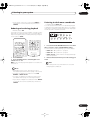
Where you place the speakers will have a big effect on the
sound. Place your speakers as shown below for the best
surround sound effect. For more tips on speaker
placement, see Placing the speakers on page 29.
Front L
Front R
Subwoofer
Center
Surround
R
Surround
L
Surround
back L
Surround
back R
11
En
VSX-54TX_0430.book 12 ページ 2004年5月6日 木曜日 午後8時7分
02
5 minute guide
Automatically setting up for
surround sound
The Auto Surround Setup measures the acoustic
characteristics of your listening area, taking into account
ambient noise, speaker size and distance, and tests for
both channel delay and channel level. After you have set
up the microphone provided with your system, the
receiver uses the information from a series of test tones
to optimize the speaker settings and equalization for your
particular room.
Make sure you do this before moving on to Playing a
source on page 14.
Important
• Make sure the microphone and speakers are not
moved during the Auto Surround Setup.
• Using the Auto Surround Setup will overwrite any
existing speaker settings in the receiver.
• The receiver will automatically exit the on-screen
menu after three minutes of inactivity.
Caution
• The test tones used in the Auto Surround Setup are
output at high volume.
2 Connect the microphone to the MCACC SETUP
MIC jack on the front panel.
Make sure there are no obstacles between the speakers
and the microphone.
• Place the microphone on the supplied microphone
stand (shown above) for the best results with the
Auto Surround Setup.
Important
• If you have a tripod, use it to place the microphone so
that it’s about ear level at your normal listening
position. Otherwise, place the microphone at ear
level using a table or a chair.
3 Press RECEIVER on the remote control, then press
the SYSTEM SETUP button.
An on-screen display (OSD) appears on your TV. Use the
/ (cursor up/down) buttons and ENTER on the
remote control to navigate through the screens and
select menu items.
4 ‘Surround Setup’ should be highlighted. Press
ENTER.
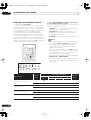
System Setup
[
[
[
[
[
[
[
1. Surround Setup
2. THX CINEMA Setup
3. Input Assign
4. Function Rename
5. Multi Room
6. 12V Trigger
Exit
]
]
]
]
]
]
]
5 ‘SurrBack System’ should be highlighted. Press
ENTER.
1.Surround Setup
[
[
[
[
[
1 Switch on the receiver and your TV.
Use the RECEIVER button to switch on.
12
En
SurrBack System
Auto Setting
Normal
Expert
Exit
]
]
]
]
]
VSX-54TX_0430.book 13 ページ 2004年5月6日 木曜日 午後8時7分
5 minute guide
02
6 Make sure ‘Normal System’ is selected, then
select ‘Exit’.
10 Confirm the speaker configuration in the OSD.
The configuration shown on-screen should reflect the
actual speakers you have.
SurrBack System
[
[
[
[
[
Normal System
Second Zone
Front Bi-Amp
MR&S
Exit
Check!!
Front
[ YES ]
Center
[ YES ]
Surround
[ YES ]
SurrBack
[ YES X 2 ]
Subwoofer
[ YES ]
]
]
]
]
]
[OK]
[Retry]
[ERR Fix SP.]
[Return to Menu]
• If you are planning on bi-amping your front speakers,
or setting up a separate speaker system in another
room, read through Surround back speaker setting on
page 50 and make sure to connect your speakers as
necessary before continuing to step 7.
7 ‘Auto Setting’ should be highlighted. Press
ENTER.
1.Surround Setup
[
[
[
[
[
8
SurrBack System
Auto Setting
Normal
Expert
Exit
If the speaker configuration displayed isn’t correct, use
the / (cursor up/down) buttons to select Retry.
Follow the instructions from step 8.
If the configuration is incorrect and you want to input the
settings manually, select ERRFix SP. Use / (cursor
up/down) to select the speaker and to specify the size
(and number for surround back). When you’re finished,
go to the next step.
If you see an ERR message in the right side column, there
may be a problem with the speaker connection. If
selecting Retry (above) doesn’t fix the problem, turn off
the power and check the speaker connections.
]
]
]
]
]
11 Make sure ‘OK’ is selected, then press ENTER.
A progress report is displayed on-screen while the
receiver outputs more test tones to determine the
optimum receiver settings for channel level, speaker
distance, and acoustic calibration EQ.
Follow the instructions on-screen.
Auto Surround Setup
Set microphone
Turn on subwoofer
Auto Surround Setup
Auto Surround Setup
Please Wait
Surround Analysis
Speaker Systems
Speaker Distance
Channel Level
Acoustic Cal EQ
Now Analyzing •••
[ Start ]
[ Cancel ]
Caution!!
Test tone is
output loudly.
• Make sure the microphone is connected.
[ Cancel ]
• If you’re using a subwoofer, switch it on and turn up
the volume.
• See below for notes regarding high background
noise levels and other possible interference.
9 Make sure ‘Start’ is selected, then press ENTER.
A progress report is displayed on-screen while the
receiver outputs test tones to determine the speakers
present in your setup. Try to be as quiet as possible while
it’s doing this.
Auto Surround Setup
Auto Surround Setup
Please Wait
Environment Check
Ambient Noise
Microphone
Speaker YES/NO
[OK]
[OK]
[OK]
[OK]
[Cancel]
Again, try to be as quiet as possible while this is
happening.
12 The Auto Surround Setup has finished! Select
‘Exit’ to go back to the Surround Setup menu.
The MCACC indicator continues to light to show the
surround settings are complete.
Now Analyzing •••
Caution!!
Test tone is
output loudly.
[OK]
[OK]
[OK]
[Cancel]
[ Cancel ]
• Do not turn down the volume during the test tones.
This may result in incorrect speaker settings.
The settings made in the Auto Surround Setup should
give you excellent surround sound from your system, but
it is also possible to adjust these settings manually using
the Surround Setup menu (starting on page 49).
13
En
VSX-54TX_0430.book 14 ページ 2004年5月6日 木曜日 午後8時7分
02
5 minute guide
You can also choose to view all the settings by selecting
Next. Press ENTER after you have finished checking
each screen. When you’re finished, select Exit to go back
to the Surround Setup menu.
Note
• If you leave a check screen for over three minutes, or
if you select Cancel at any time during the Auto
Surround Setup, the receiver automatically exits and
no settings will be made.
• Remember to disconnect the microphone after
you’ve finished the Auto Surround Setup.
Other problems when using the Auto
Surround Setup
If the room environment is not optimal for the Auto
Surround Setup (too much background noise, echo off
the walls, obstacles blocking the speakers from the
microphone) the final settings may be incorrect. Check
for household appliances (air conditioner, fridge, fan,
etc.), that may be affecting the environment and switch
them off if necessary.
Some older TVs may interfere with the operation of the
microphone. If this seems to be happening, switch off the
TV when doing the Auto Surround Setup.
Checking the settings on your DVD
(or other) player
Before continuing, you may want to check the digital
audio output settings on your DVD player and digital
satellite receiver.
• Check that your DVD player/satellite receiver is
set to output Dolby Digital, DTS and 88.2/96kHz PCM
(2 channel) audio.
If there is an option for MPEG audio, set this to convert
the MPEG audio to PCM.
If you connected the multichannel analog outputs of the
player to this receiver, make sure that the player is set to
output multichannel analog audio.
Note
• Depending on your DVD player or source discs, you
may only get digital 2 channel stereo and analog
sound. In this case, select one of the surround
listening modes (see Listening in surround sound on
page 37 if you need to do this) if you want
multichannel surround sound.
14
En
Playing a source
Here are the basic instructions for playing a source (such
as a DVD disc) with your home theater system.
1 Turn on the power of the playback component
(for example a DVD player), your TV and subwoofer
(if you have one).
• If your source is the TV’s built-in tuner, then switch to
the channel you want to watch, otherwise make sure
that the TV’s video input is set to this receiver. (For
example, if you connected this receiver to the VIDEO
1 jacks on your TV, make sure that VIDEO 1 input is
now selected.)
2 If the receiver isn’t already on, press RECEIVER
to switch it on.
3 Change the receiver input to the source you
want to play.
You can use the front panel MULTI JOG dial or the
dedicated MULTI CONTROL buttons on the remote
control.
4 Start playback of the DVD (or other component).
If you’re playing a Dolby Digital or DTS surround sound
DVD disc, you should hear surround sound. If you are
playing a stereo source, you will only hear sound from the
front left/right speakers in the default listening mode.
• See also Listening to your system on page 37 for
more information on different ways of listening to
sources.
5 Use the MASTER VOLUME control (front panel or
remote) to adjust the volume level.
• Turn down the volume of your TV so that all the sound
is coming from the speakers connected to this
receiver.
Note
• For more detailed surround sound setup, see The
Surround Setup menu on page 49.
VSX-54TX_0430.book 15 ページ 2004年5月6日 木曜日 午後8時7分
Connecting your equipment
03
Chapter 3
Connecting your equipment
This receiver provides you with almost limitless possibilities for connecting your audio/video system, but it doesn’t
have to be difficult. Depending on your needs, you could be up and running in no time after a few simple connections.
This section has been designed so that you can read through this short introduction, then jump to the specific
connections that you need to make. For a basic home theater setup, you may only need to look through the TV, DVD
and speaker connections.
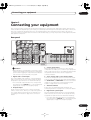
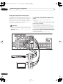
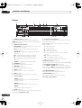
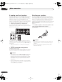
Rear panel
2
5
3
6
8
4
1
8
7
11
13
14
10
17
9
16
12
15
Caution
• Before making or changing the connections, switch
off the power and disconnect the power cord from the
power outlet. Plugging in components should be the
last connection you make with your system.
1 Digital audio coaxial inputs
Two coaxial digital audio inputs for connecting digital
audio sources to this receiver. All the inputs are freely
assignable to input functions for maximum flexibility.
• If a connected component does not correspond to
the input function (DVD/LD, etc.), see Assigning the
digital inputs on page 72 to assign it properly.
2 IR input/output
An IR connection allows you to connect an external
remote control sensor, when your component system is
in a closed cabinet or shelving unit, for example. See
Connecting an IR receiver on page 69 for connection
details.
3 Control input/output
Mini-plug terminals for connection to other Pioneer
components to enable you to control all your equipment
from a single remote sensor. See Operating other Pioneer
components with this unit's sensor on page 60 for
connection details.
4 Stereo analog audio source inputs/outputs
Four sets of analog audio jacks for connection to audio
sources such as CD players, tape decks and turntables.
The CD-R/TAPE1 and MD/TAPE2 functions also feature
outputs for recording. See Connecting analog audio
sources on page 26 for connection details.
5 Antenna terminals
Connections for AM and FM radio antennas. See
Connecting antennas on page 30 for connection details.
6 Digital audio optical inputs
Two optical digital audio inputs for connecting digital
audio sources to this receiver. All the inputs are freely
assignable to input functions for maximum flexibility.
• If a connected component does not correspond to
the input function (DVD/LD, etc.), see Assigning the
digital inputs on page 72 to assign it properly.
15
En
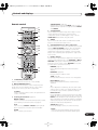
VSX-54TX_0430.book 16 ページ 2004年5月6日 木曜日 午後8時7分
03
Connecting your equipment
7 Digital audio outputs
Two optical digital audio outputs for connecting to a CDR, MD or other digital recorder. See Connecting a VCR or
DVD recorder on page 22 for connection details.
8 Multi-room and source outputs
The analog audio outputs are for connection to a second
amplifier in a separate room. The MULTI-ROOM &
SOURCE composite video output is for connection to a
second monitor or TV in a separate room. See Multi-room
listening on page 67.
9 Audio/video source inputs
Each of the six source input functions has stereo analog
audio jacks, a composite video jack and an S-video jack
for basic connections. On top of these, you can assign
digital audio and component video jacks to input
functions as necessary. As well as audio/video inputs,
the two input functions VCR1/DVR and VCR2 also have
audio/video outputs for recording. See Connecting a VCR
or DVD recorder on page 22 for connection details.
10 Monitor video outputs
Two video outputs consisting of a standard composite
video output and an S-video output, for connection to
monitors and TVs. See Connecting your TV on page 18 for
connection details.
11 Multichannel pre-amplifier outputs
Multichannel pre-amp outputs that you can use to
connect separate amplifiers for center, surround,
surround back and subwoofer channels. See Multi-room
listening on page 67 for connection details.
12 Multichannel analog audio inputs
7.1 channel analog inputs for connection to a component
with multichannel analog outputs. See Connecting the
multichannel analog outputs on page 20 for connection
details.
13 Component video inputs/output
The two component video inputs are freely assignable to
any of the audio/video input functions. The component
video output is for connection to a monitor or TV. See
Connecting other video sources on page 23 for
connection details.
14 12V trigger jack
This terminal outputs DC 12V according to the input
functions (100 mA max.). See Switching components on
and off using the 12 volt trigger on page 60 for connection
details.
15 RS-232C connector
This port is provided for connecting a personal computer
for graphical output when using Advanced MCACC.
16 Speaker terminals
These are the main speaker terminals for front, center,
surround and surround back speakers. See Installing
your speaker system on page 28 for connection details.
16
En
17 AC power outlet (Switched 100W max.)
This 120V AC power outlet can be used to power another
component in your setup (up to 100 W). Power to this
outlet is switched off when the receiver is in standby.
About the video converter
The video converter allows you to connect various video
sources using composite, S-video or component video
connections and the signal will be output through all of
the MONITOR VIDEO OUT jacks. The only exception is
component video input, which is only output from the
component video output. Therefore, if you want to
connect any source using component video, you must
also connect your TV using component video. If several
video components are connected to the same input
function, the converter gives priority to component, Svideo, then composite (in that order).
The following chart shows when the video signal will be
converted from the various video inputs (left column) for
output to the MONITOR VIDEO OUT jacks (top row):
Video
terminal
MONITOR OUT
VIDEO
(Composite)
S-VIDEO
COMPONENT
VIDEO
VIDEO IN
(Composite)
S-VIDEO IN
COMPONENT
VIDEO IN
• The mark above indicates that the component
video input must be assigned before it will be output
(see Assigning the component video inputs on
page 72 for more on this).
• When recording video sources however, you won’t be
able to record sources connected to the component
video inputs. With composite and S-video sources,
they must be connected using the same type of video
cable as you used to connect the recorder to the
receiver.
• Also note that this feature is available with NTSC
signals only. For a PAL signal, make sure you’ve used
the same type of cable for your video component and
monitor connections.
VSX-54TX_0430.book 17 ページ 2004年5月6日 木曜日 午後8時7分
Connecting your equipment
03
About cable types
S-video cables
Analog audio cables
S-video cables give you clearer picture reproduction than
regular video cables by sending separate signals for the
luminance and color.
Use stereo RCA phono cables to connect analog audio
components. These cables are typically red and white,
and you should connect the red plugs to R (right)
terminals and white plugs to L (left) terminals.
R
S Video
L
Component video cables
Use component video cables to get the best possible
color reproduction of your video source. The color signal
of the TV is divided into the luminance (Y) signal and the
color (PB and PR) signals and then output. In this way,
interference between the signals is avoided.
Digital audio cables
Commercially available coaxial digital audio cables or
optical cables should be used to connect digital
components to this receiver.
Y
PB
Green
Blue
Coaxial digital audio cable
Optical cable
• When connecting optical cables, be careful when
inserting the plug not to damage the shutter
protecting the optical socket.
• When storing optical cable, coil loosely. The cable
may be damaged if bent around sharp corners.
PR
Red
When making cable connections
Be careful not to arrange cables in a manner that bends
the cables over the top or around this unit. If the cables
are laid on top of the unit, the magnetic field produced by
the transformers in this unit may cause a humming noise
to come from the speakers.
• You can also use a standard RCA video cable for
coaxial digital connections.
Video cables
Standard RCA video cables
These cables are the most common type of video
connection and should be used to connect to the
composite video terminals. They have yellow plugs to
distinguish them from cables for audio.
VID
EO
17
En
VSX-54TX_0430.book 18 ページ 2004年5月6日 木曜日 午後8時7分
03
Connecting your equipment
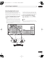
Connecting your TV
This page shows you how to connect your TV to the
receiver. To be able to play the sound from the TV’s builtin tuner, connect the analog audio outputs from your TV
to this receiver.
If your TV has a built-in digital decoder, you can connect
the digital audio output to this receiver to enjoy Dolby
Digital and DTS sound from digital TV broadcasts.
1 Connect the MONITOR OUT video jack on this
receiver to a video input on your TV.
Make sure you don’t connect to the MONITOR OUT
connection for MULTI ROOM & SOURCE.
• You can use a standard RCA video cable to connect
to the composite video jack, or for higher quality
video, you can use an S-video cable to connect to the
S-video jack (S-VIDEO).
• See Using the component video jacks on page 24 if
you want to use the component video outputs to
connect this receiver to your TV.
2 Connect the analog audio outputs from your TV
to the TV/SAT inputs on this receiver.
• Use a stereo RCA phono cable for the connection.
3 Connect an optical digital audio output from
your TV to the DIGITAL 1 (TV/SAT) input on this
receiver.
• Use an optical cable for the connection.
• If your TV only has a coaxial digital output, you can
connect it to one of the coaxial inputs on this receiver
using a coaxial digital audio cable. When you set up
the receiver you’ll need to tell the receiver which
input you connected the TV to (see Assigning the
digital inputs on page 72).
Note
• If your TV doesn’t have a digital audio output, omit
step 3 above.
• See About the video converter on page 16 if you plan
on connecting your other video components using
different types of video cables than for your TV.
VSX-54TX
2
R
L
ANALOG AUDIO OUT
1
3
OPTICAL
COAXIAL
VIDEO
IN
DIGITAL AUDIO OUT
TV
18
En
S-VIDEO
IN
VSX-54TX_0430.book 19 ページ 2004年5月6日 木曜日 午後8時7分
Connecting your equipment
03
Connecting a DVD player
VSX-54TX
OPTICAL
COAXIAL
DIGITAL OUT
1
R
AUDIO L
ANALOG OUT
2
S-VIDEO
VIDEO OUT
3
DVD player
Different DVD players offer a different selection of
connections, but all should give you at least a digital
audio output, stereo analog audio outputs and a video
output. Additionally, you may have a player with
multichannel analog audio outputs and different kinds of
video outputs to choose from.
1 Connect a coaxial digital audio output on your
DVD player to the DIGITAL 3 (DVD/LD) input on this
receiver.
• Use a coaxial digital audio cable for the connection.
• If your DVD player only has an optical digital output,
you can connect it to one of the optical inputs on this
receiver using an optical cable. When you set up the
receiver you’ll need to tell the receiver which input
you connected the player to (see Assigning the digital
inputs on page 72).
2 If your DVD player only has stereo analog audio
outputs, connect these to the DVD/LD AUDIO inputs
on this receiver.
• Use stereo RCA phono cables for the connection.
• If your DVD player has multichannel analog outputs,
see Connecting the multichannel analog outputs
below for how to connect it.
3 Connect a composite or S-video output on your
DVD player to the DVD/LD VIDEO or DVD/LD SVIDEO input on this receiver.
• Use a standard RCA video cable or an S-video cable
for the connection.
• See About the video converter on page 16 if you plan
to use a different type of video cable than you used to
connect your TV.
• If your player also has a component video output, you
can connect this too. See Using the component video
jacks on page 24 for more on this.
19
En
VSX-54TX_0430.book 20 ページ 2004年5月6日 木曜日 午後8時7分
03
Connecting your equipment
Connecting the multichannel analog outputs
VSX-54TX
R
FRONT
R
SURR.
L SUB W. CENTER
R
L
MULTI CH
OUTPUT
1
L
SURR.
BACK
MULTI CH. OUT
2
DVD player
For DVD Audio and SACD playback, your DVD player may
have 5.1, 6.1 or 7.1 channel analog outputs (depending
on whether your player supports surround back
channels).
1 Connect the front, surround, center and
subwoofer outputs on your DVD player to the
corresponding MULTI CH IN jack on this receiver.
• Use standard RCA phono cables for the connections.
• Take care to connect each output to its
corresponding input on the receiver.
2 If your DVD player also has outputs for surround
back channels, connect these to the corresponding
MULTI CH IN jacks on this receiver.
• Use standard RCA phono cables for the connections.
20
En
• If there is only a single surround back output, be sure
to connect it to the SURROUND BACK L jack on this
receiver.
Note
• To listen to multichannel analog audio you’ll need to
press MULTI CH INPUT on the remote (see Using the
multichannel analog inputs on page 40 for more on
this).
VSX-54TX_0430.book 21 ページ 2004年5月6日 木曜日 午後8時7分
Connecting your equipment
03
Connecting a satellite/cable receiver or other set-top box
Satellite and cable receivers, and terrestrial digital TV
tuners are all examples of so-called ‘set-top boxes’.
• If your set-top box only has a coaxial digital output,
you can connect it to one of the coaxial inputs on this
receiver using a coaxial digital audio cable. When
you set up the receiver you’ll need to tell the receiver
which input you connected the set-top box to (see
Assigning the digital inputs on page 72).
1 Connect a set of audio/video outputs on the settop box component to the TV/SAT AUDIO and VIDEO
inputs on this receiver.
• Use a stereo RCA phono cable for the audio
connection and a standard RCA video or S-video
cable for the video connection.
Note
• See About the video converter on page 16 if you plan
to use a different type of video cable than you used to
connect your TV.
• If your satellite/cable receiver doesn’t have a digital
audio output, omit step 2 above.
• If you’ve already connected your TV to the TV/SAT
inputs above, simply choose another input. However,
you’ll need to tell the receiver which input you
connected the set-top box to (see Assigning the
digital inputs on page 72).
2 Connect an optical digital audio output from
your set-top box component to the DIGITAL 1 (TV/
SAT) input on this receiver.
• Use an optical cable for the connection.
VSX-54TX
DIGITAL OUT
2
1
OPTICAL
COAXIAL
R
AUDIO
L
VIDEO
S-VIDEO
AV OUT
STB
21
En
VSX-54TX_0430.book 22 ページ 2004年5月6日 木曜日 午後8時7分
03
Connecting your equipment
Connecting a VCR or DVD recorder
• For a second recorder, use the VCR2 outputs.
This receiver has two sets of audio/video inputs and
outputs suitable for connecting analog or digital video
recorders, including VCRs, DVD-recorders and HDD
recorders.
• See About the video converter on page 16 if you plan
to use a different type of video cable than you used to
connect your TV.
1 Connect a set of audio/video outputs on the
recorder to the VCR 1/DVR AUDIO and VIDEO inputs
on this receiver.
• Use a stereo RCA phono cable for the audio
connection and a standard RCA video or S-video
cable for the video connection.
3 Connect an optical digital audio output from the
recorder to a digital input on this receiver.
The example illustration below shows a recorder
connected to the optical DIGITAL 2 (CD-R/TAPE1) input.
When you set up the receiver you’ll need to tell the
receiver which input you connected the recorder to (see
Assigning the digital inputs on page 72).
• Use a coaxial digital audio cable or an optical cable
for the connection depending on the type of input you
used.
• The digital outputs from another recorder can be
connected to any spare digital audio input on this
receiver. You can assign it when setting up the
receiver (see Assigning the digital inputs on page 72).
• For a second recorder, use the VCR2 inputs.
2 Connect a set of audio/video inputs on the
recorder to the VCR1/DVR AUDIO and VIDEO outputs
on this receiver.
• Use a stereo RCA phono cable for the audio
connection and a standard RCA video or S-video
cable for the video connection.
Note
• If your video component doesn’t have a digital audio
output, omit step 3 above.
VSX-54TX
3
OPTICAL
1
COAXIAL
DIGITAL OUT
R
AUDIO
L
VIDEO
AV OUT
DVR, VCR, etc.
22
En
S-VIDEO
R
AUDIO
VIDEO
L
AV IN
S-VIDEO
2
VSX-54TX_0430.book 23 ページ 2004年5月6日 木曜日 午後8時7分
Connecting your equipment
03
Connecting other video sources
• See About the video converter on page 16 if you plan
to use a different type of video cable than you used to
connect your TV.
You can basically use any of the audio/video inputs on
this receiver for any kind of video source. The example
illustration below shows a component connected to the
VCR2 inputs.
2 If the source component has a digital audio
output, connect it to a spare digital audio input on
this receiver.
• Use a coaxial digital audio cable or an optical cable
for the connection depending on the type of input you
used.
1 Connect the analog audio outputs and a video
output of the source component to a set of spare
audio/video inputs on this receiver.
• Use a stereo RCA phono cable for the audio
connection and a standard RCA video or S-video
cable for the video connection.
• You may need to assign the digital input you used
when setting up the receiver (see Assigning the
digital inputs on page 72).
VSX-54TX
2
DIGITAL OUT
1
OPTICAL
COAXIAL
R
AUDIO
L
VIDEO
S-VIDEO
AV OUT
LD player, video player, TV game, etc.
23
En
VSX-54TX_0430.book 24 ページ 2004年5月6日 木曜日 午後8時7分
03
Connecting your equipment
Using the component video jacks
Component video should deliver superior picture quality
when compared to composite or S-video. A further
advantage (if your source and TV are both compatible) is
progressive-scan video, which delivers a very stable,
flicker-free picture. See the manuals that came with your
TV and source component to check whether they are
compatible with progressive-scan video.
Important
• If you connect any source component to the receiver
using a component video input, you should also have
your TV connected to this receiver's component video
MONITOR output.
1 Connect the component video outputs of your
source to a set of component video inputs on this
receiver.
Use a three-way component video cable for the
connection.
2 Assign the component video inputs to the input
source you’ve connected.
This must be done so that they can be used in
conjunction with the audio/video input(s) to which you
have connected the component above (see Assigning the
component video inputs on page 72 for more on this).
3 Connect the COMPONENT VIDEO MONITOR OUT
jacks on this receiver to the component video inputs
on your TV or monitor.
• Use a three-way component video cable.
VSX-54TX
1
Y
PB
PR
DVD player
COMPONENT
VIDEO OUT
2
Y
PB
PR
COMPONENT
VIDEO IN
TV
24
En
VSX-54TX_0430.book 25 ページ 2004年5月6日 木曜日 午後8時7分
Connecting your equipment
03
Connecting digital audio sources
This receiver has both digital inputs and outputs,
allowing you to connect digital components for playback
and for making digital recordings. Many digital
components also have analog connections for recording
analog sources (such as a turntable or tape deck). See
Connecting analog audio sources below for more on this.
1 Connect a coaxial digital output on your digital
component to the DIGITAL 4 (CD) input on this
receiver.
• Use a coaxial digital audio cable for the connection.
• If your digital compoent only has an optical digital
output, you can connect it to one of the optical inputs
on this receiver using an optical cable. When you set
up the receiver you’ll need to tell the receiver which
input you connected the player to (see Assigning the
digital inputs on page 72).
• The digital outputs from other components can be
connected to any spare digital audio inputs on this
receiver. You can assign them when setting up the
receiver (see Assigning the digital inputs on page 72).
2 Connect one of the DIGITAL outputs on this
receiver to a digital input on the component.
• Use an optical cable to connect to the DIGITAL
OUT1 or OUT2 (OUT2 is shown in the illustration
below).
Note
• In order to record some digital sources, you must
make analog connections as explained in Connecting
analog audio sources below.
VSX-54TX
1
OPTICAL
COAXIAL
DIGITAL OUT
OPTICAL
2
DIGITAL IN
CD-R, MD, DAT, etc.
25
En
VSX-54TX_0430.book 26 ページ 2004年5月6日 木曜日 午後8時7分
03
Connecting your equipment
Connecting analog audio sources
This receiver features four stereo audio-only inputs. Two
of these inputs have corresponding outputs for use with
audio recorders.
1 Connect the analog audio outputs of the source
component to a set of spare audio inputs on this
receiver.
• If you’re connecting a tape deck, MD recorder, etc.,
connect the analog audio outputs (REC) to the analog
audio inputs on the recorder.
• Use a stereo RCA phono cable for the connections.
2 Connect the stereo audio outputs to the LINE
inputs on this receiver.
• If you use a turntable with this LINE IN jack only
connect one with a built-in phono equalizer.
1
OUT
PLAY
IN
REC
R
AUDIO IN/OUT
L
Tape deck, etc.
VSX-54TX
2
Turntable (with a built-in phono equalizer)
26
En
VSX-54TX_0430.book 27 ページ 2004年5月6日 木曜日 午後8時7分
Connecting your equipment
03
Connecting a component to the front panel inputs
The front panel inputs include a composite video jack
(VIDEO), an S-video jack (S-VIDEO), stereo analog audio
inputs (AUDIO L/R) and an optical digital audio input
(DIGITAL). You can use these connections for any kind of
audio/video component, but they are especially
convenient for portable equipment such as camcorders,
video games and portable audio/video equipment.
• The input signals can be accessed by selecting
VIDEO as the input source.
• Pull down the front cover where indicated to access
the front panel inputs.
• The illustration below shows example connections to
a portable DVD player. Note that you may need a
specialized optical cable for this connection.
VSX-54TX
COLOR
VIDEO IN/OUT
AUDIO IN/OUT
BRIGHT
MONITOR
PHONES
ON/OFF
HOLD
DIGITAL OUT (OPTICAL)
Portable DVD player, etc.
27
En
VSX-54TX_0430.book 28 ページ 2004年5月6日 木曜日 午後8時7分
03
Connecting your equipment
Installing your speaker system
main surround speakers should always be connected as
a pair, but you can connect just one surround back
speaker if you like (it must be connected to the left
surround back terminal). You can use speakers with a
nominal impedance between 6–16Ω (please see
Switching the speaker impedance on page 63 if you plan
to use speakers with an impedance of less than 8Ω).
To take full advantage of the receiver’s surround sound
capabilities connect front, center, surround and
surround back speakers, as well as a subwoofer.
Although this is ideal, other configurations with fewer
speakers—no subwoofer or no center speaker, or even
no surround speakers—will work. At the very least, front
left and right speakers only are necessary. Note that your
Front
right
Front
left
Subwoofer
Center
LINE LEVEL
INPUT
VSX-54TX
Surround
left
28
En
Surround
back left
Surround
back right
Surround
right
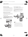
VSX-54TX_0430.book 29 ページ 2004年5月6日 木曜日 午後8時7分
Connecting your equipment
03
Connecting the speakers
Each speaker connection on the receiver comprises a
positive (+) red, and negative (–) black terminal. For
proper sound you should take care to match these up
with the terminals on the speakers themselves.
• If you only have one surround back speaker, hook it
up to the surround back left (Single) terminal.
Caution
• Make sure that all the bare speaker wire is twisted
together and inserted fully into the speaker terminal.
If any of the bare speaker wire touches the back panel
it may cause the power to cut off as a safety measure.
Bare wire connections
Before you start connecting the speakers, make sure that
the speaker cable you’re going to use is properly
prepared with about 3/8 in. (10 mm) of insulator stripped
from each wire, and the exposed wire strands twisted
together (fig. A).
To connect a terminal, unscrew the terminal a few turns
until there is enough space to insert the exposed wire
(fig. B). Once the wire is in position, tighten the terminal
until the wire is firmly clamped (fig. C).
3 / 8 inch (10mm)
• The surround speaker terminals on this receiver can
be connected in a number of ways, depending on
your setup. See Speaker Setting on page 50 for an
overview of the possible configurations.
• Other connections on page 65 provides greater detail
on alternate speaker setups such as using speaker
system B (page 65), bi-amping (page 66) and biwiring (page 66).
Placing the speakers
Where you put your speakers in the room has a big effect
on the quality of the sound. The following guidelines
should help you to get the best sound from your system.
• The subwoofer can be placed on the floor. Ideally, the
other speakers should be at about ear-level when
you’re listening to them. Putting the speakers on the
floor (except the subwoofer), or mounting them very
high on a wall is not recommended.
• For the best stereo effect, place the front speakers
6–9 ft. apart, at equal distance from the TV.
• Install the center speaker above or below the TV so
that the sound of the center channel is localized at
the TV screen.
• When placing speakers near the TV, use magnetically
shielded speakers to prevent possible interference,
such as discoloration of the picture when the TV is
switched on. If you do not have magnetically shielded
speakers and notice discoloration of the TV picture,
move the speakers farther away from the TV.
• If possible, install the surround speakers slightly
above ear level.
fig. A
fig. B
fig. C
• If you have two surround back speakers THX
recommends placing them together and the same
distance from your listening position.
Banana plug connections
Front L
If you want to use speaker cables terminated with banana
plugs, screw the speaker terminal fully shut then plug the
banana plug into the end of the speaker terminal.
Front R
Subwoofer
Center
Surround
R
Surround
L
Surround
back L
Note
• Please refer to the manual that came with your
speakers for details on how to connect the other end
of the speaker cables to your speakers.
• If you are using a THX certified subwoofer use the
THX INPUT jack on the subwoofer (if your subwoofer
has one) or switch the filter position to THX on your
subwoofer.
Surround
back R
Caution
• Make sure that all speakers are securely installed.
This not only improves sound quality, but also
reduces the risk of damage or injury resulting from
speakers being knocked over or falling in the event of
external shocks such as earthquakes.
29
En
VSX-54TX_0430.book 30 ページ 2004年5月6日 木曜日 午後8時7分
Connecting your equipment
03
Connecting antennas
The supplied antennas provide a simple way to listen to
AM and FM radio. If you find that reception quality is
poor, an outdoor antenna should give you better sound
quality—see Connecting external antennas below.
FM wire
antenna
AM loop antenna
VSX-54TX
AM loop antenna
1
Note
Assemble the stand as shown in the illustration.
fig. A
fig. B
fig. C
• The signal ground () is designed to reduce noise
that occurs when an antenna is connected. It is not
an electrical safety ground.
FM wire antenna
• Bend the stand in the direction indicated (fig. A).
• Clip the loop into the stand (fig. B).
• It’s possible to fix the AM antenna to a wall (fig. C).
Before fixing, make sure that the reception is
satisfactory.
2 Pull off the protective shields of both AM
antenna wires.
3 Press the AM LOOP antenna terminal tabs to
open and insert one wire into each terminal.
4
Release the tabs to secure the AM antenna wires.
5 Place the AM antenna on a flat surface and point
in the direction giving the best reception.
Avoid placing near computers, television sets or other
electrical appliances and do not let it come into contact
with metal objects.
30
En
• Connect the FM wire antenna to the FM UNBAL
75Ω terminal.
For best results, extend the FM antenna fully and fix to a
wall or door frame. Don’t drape loosely or leave coiled up.
VSX-54TX_0430.book 31 ページ 2004年5月6日 木曜日 午後8時7分
Connecting your equipment
03
Connecting external antennas
• The receiver should be disconnected by removing the
mains plug from the wall socket when not in regular
use (for example, when on vacation).
To improve FM reception connect an external FM
antenna to the FM UNBAL 75Ω.
1 Plug the supplied power cord into the AC IN
socket on the back of the receiver.
2
Plug the other end into a power outlet.
About the AC outlet
75Ω coaxial cable
(Switched 100W max.)
Power supplied through this outlet is turned on and off by
the receiver's STANDBY/ON switch. Total electrical
power consumption of connected equipment should not
exceed 100 W (0.8 A).
ANTENNA
To improve AM reception, connect a 15–18 ft. length of
vinyl-coated wire to the AM LOOP terminals without
disconnecting the supplied AM loop antenna.
For the best possible reception, suspend horizontally
outdoors.
Outdoor antenna
Indoor antenna
(vinyl-coated wire)
Caution
• Do not connect a TV set, monitor, heater, or similar
appliance to this unit's AC outlet.
• Do not connect appliances with high power
consumption to the AC outlet in order to avoid
overheating and fire risk. This can also cause the
receiver to malfunction.
• Since a subwoofer can exceed the 100W maximum
when playing sources at a high volume, it is best not
to connect a subwoofer to the AC outlet.
15–18 ft.
Plugging in the receiver
Only plug in after you have connected all your
components to this receiver, including the speakers.
Caution
• Handle the power cord by the plug part. Do not pull
out the plug by tugging the cord, and never touch the
power cord when your hands are wet, as this could
cause a short circuit or electric shock. Do not place
the unit, a piece of furniture, or other object on the
power cord or pinch the cord in any other way. Never
make a knot in the cord or tie it with other cables. The
power cords should be routed so that they are not
likely to be stepped on. A damaged power cord can
cause a fire or give you an electric shock. Check the
power cord once in a while. If you find it damaged,
ask your nearest Pioneer authorized independent
service company for a replacement.
• Do not use any power cord other than the one
supplied with this unit.
• Do not use the supplied power cord for any purpose
other than that described below.
31
En
VSX-54TX_0430.book 32 ページ 2004年5月6日 木曜日 午後8時7分
04
Controls and displays
Chapter 4
Controls and displays
Front panel
1
2 3
4 5
6
7
8
9
10
11 12
54
13
14
19
20
15
16
21
23
5 STANDBY indicator
Lights when the receiver is in standby.
2 STANDBY/ON
Press STANDBY/ON to switch the receiver on or into
standby.
7 Display
See Display on page 34.
4 ENTER
Use to confirm your selection (with the MULTI JOG dial).
32
22
18
1 MULTI JOG dial
Depending on the operation, you can use this to select an
input source or listening mode, as well as for tuner and
system settings. It can often be used instead of the
remote control / (cursor up/down) buttons.
3 Surround listening mode buttons (page 37)
Use to select the MOVIE and MUSIC surround listening
modes.
En
17
6 Remote sensor
Receives the signals from the remote control.
8 Advanced MCACC indicator (page 41)
Lights when Acoustic Calibration EQ is on Acoustic
Calibration EQ is automatically set to ALL CH ADJUST
after the Auto Surround Setup has been completed.
9 STEREO/DIRECT (page 40)
Switches the receiver into STEREO mode if it was in a
different listening mode or toggles between DIRECT and
STEREO.
VSX-54TX_0430.book 33 ページ 2004年5月6日 木曜日 午後8時7分
Controls and displays
04
10 MULTI CH IN (page 40)
Press to select the component connected to the MULTI
CH IN terminals (for example, a DVD-Audio player).
BASS/TREBLE
Use to select whether the bass or treble will be
adjusted.
11 ACOUSTIC EQ (page 41)
Press to select an acoustic calibration EQ setting.
+/–
Use to adjust the frequency setting.
12 MASTER VOLUME dial
Adjusts the volume.
22 MCACC SETUP MIC jack
Use to connect the supplied microphone.
13 MULTI JOG CONTROL
Use the SET UP button to access the System Setup
menu, and RETURN to exit the current menu screen.
23 VIDEO INPUT jacks (page 22)
• DIGITAL IN – Connect a game console, portable DVD
player, video camera (etc.), that has an optical digital
connection.
14 STREAM DIRECT (page 37)
Press to switch on/off Direct playback.
15 HI-BIT/HI-SAMPLING (page 43)
Use this to switch the audio scaler on or off.
• S-VIDEO – Connect a video camera (etc.), that has an
S-video out.
• VIDEO / AUDIO (L/R) – Connect a video camera, etc.
that has standard RCA video/audio outputs.
16 SB CH MODE (page 42)
Use to select the surround/virtual back channel mode.
17 TUNER controls (page 46)
Use the front panel tuner controls for tuning into stations
and recalling station presets.
BAND
Press to select the AM or FM band.
CLASS
Press repeatedly to switch the preset station classes.
SELECT
Switches between the station memory and frequency
select mode when using the – /+ buttons.
– /+
Selects station memories or frequencies when using
the tuner.
TUNER EDIT
Press to memorize and name a station for recall with
the MULTI JOG dial.
18 MULTI ROOM & SOURCE controls
If you’ve made multi-room connections (see Multi-room
listening on page 67) use these controls to control the
sub room from the main room (see Using the multi-room
controls on page 68).
19 PHONES jack (page 40)
Use to connect headphones (no sound will be heard
through the speakers).
20 SPEAKERS (page 65)
Depending on the surround back speaker setting
(page 50), press either to switch the speaker system or
simply to switch it off (See Switching the speaker system
on page 65 for more on this).
21 TONE CONTROL
TONE
Press to switch the tone controls on or off (bypass).
33
En
VSX-54TX_0430.book 34 ページ 2004年5月6日 木曜日 午後8時7分
Controls and displays
04
Display
1
8
2
9 10
3
4
11
1 SIGNAL indicators (page 41)
Light to indicate the currently selected input signal.
AUTO lights when the receiver is set to select the input
signal automatically.
2
Digital format indicators
• PRO LOGIC II – Lights during Dolby Pro Logic II and
Pro Logic IIx processing.
• Neo:6 – Lights during Neo:6 processing with 2channel sources.
• 2 DIGITAL – Lights when a Dolby Digital signal is
detected.
• DTS – Lights when a DTS signal is detected.
• ES – Lights when a decoding DTS-ES audio.
• EX – Lights when a Dolby Digital EX signal is
detected.
• STEREO – Lights during 2-channel playback.
3 LOUDNESS (page 44)
Lights when Loudness listening is active.
7
12 13
14
9 Program format indicators
These change according to which channels are active in
Dolby, DTS and sources.
LS, S and RS will light at the same time to indicate 6.1
channel sources.
• L – Left front channel
• C – Center channel
• R – Right front channel
• LS – Left surround channel
• S – Surround channel (mono) or surround back
channel
• RS – Right surround channel
• LFE – Low frequency effects channel
•
– Lights when an LFE signal is detected
10 Speaker indicators (page 65)
Lights to indicate the current speaker system, A and/or B.
4 MIDNIGHT (page 44)
Lights when Midnight listening is active.
5 TONE (page 44)
Lights when the tone control is switched on.
12 Hi-BIT/SAMPLING (page 43)
Lights when the audio scalar is switched on.
6 DNR (page 45)
Lights when digital noise reduction is switched on.
13 MULTI-ROOM (page 67)
Lights when the multi room feature is active.
7
14 Volume level indicator
Tuner indicators
MONO (page 46)
Lights when the tuner MPX mode is set to mono.
TUNED
Lights when tuned to a broadcast.
8 SB CH (page 42)
Indicates the surround back channel (or Virtual Surround
Back) setting (AUTO, ON or OFF).
34
6
11 Listening mode indicators (page 37)
Shows MOVIE or MUSIC when a surround listening
mode is selected. DSP will light with a box around it when
one of the advanced (DSP) listening modes is selected.
STEREO (page 46)
Lights when listening to a stereo FM broadcast in
auto/stereo mode.
En
5
VSX-54TX_0430.book 35 ページ 2004年5月6日 木曜日 午後8時7分
Controls and displays
04
Remote control
9
10
11
1
2
1
3
12
13
14
4
15
16
5
17
4 SYSTEM SETUP
Use to display the System Setup menu (page 71). Also
used to display a menu when controlling other
components (such as a DVD player or TV), or as the
TUNER EDIT button when using the tuner.
5 AUDIO
Use to switch the audio tracks of a DVD when a DVD
player is selected as the input source.
6 Command buttons for other components
Use these buttons to control the component you selected
with the MULTI CONTROL buttons. They are available
once you’ve programmed the remote to control the
appropriate component (for example, your TV or DVD
player). See Controlling other equipment on page 53 for
more on this.
7 Number buttons
The operation of these buttons depends on whether the
remote control has been set to the RECEIVER or MULTI
CONTROL setting (see Controlling other equipment on
page 53 for more on this). When RECEIVER is selected,
you’ll be able to select the following:
6
7
8
STEREO/DIRECT (page 40)
Switches the receiver into STEREO mode if it was in
a different listening mode or toggles between DIRECT
and STEREO.
18
19
DIMMER (page 63)
Use to adjust the brightness of the front panel
display.
LOUDNESS (page 44)
Press to switch Loudness on/off.
TONE (page 44)
Press to switch the tone controls on or off (bypass).
1 RECEIVER (STANDBY/ON)
Press to switch the receiver on or into standby.
2 MULTI CONTROL buttons
These buttons are the basic controls that switch the
mode of the receiver and the remote control, which
allows you to control your other components.
TV CONT
Press so that the remote control can operate the TV
control commands.
3
Listening mode buttons (page 37)
MOVIE / MUSIC
Press to select the surround listening mode you want
(see Listening in surround sound on page 37).
After selecting a MOVIE or MUSIC listening mode
above, use these to select the options available.
ENTER
Use to confirm your selection.
BASS/TREBLE (page 44)
Use to select whether the bass or treble will be
adjusted.
+/–
Use to adjust the sound delay, the tone, effect and
channel levels, as well as to change Dolby Pro Logic
II / Dolby Pro Logic IIx Music parameter settings.
EFFECT/CH SEL
Press repeatedly to select a channel, then use –/+ to
adjust the level (see Tip on page 52). Also selects the
EFFECT mode, Dolby Pro Logic II / Dolby Pro Logic IIx
Music parameters (see page 39) and the sound delay
setting (see page 62). You can then use the + and –
buttons to make these adjustments.
SIGNAL SEL (page 41)
Press repeatedly to select one of the following:
• AUTO
If there are analog and digital signals input, the
receiver automatically selects the digital signal.
35
En
VSX-54TX_0430.book 36 ページ 2004年5月6日 木曜日 午後8時7分
04
Controls and displays
• DIGITAL
Selects an optical or coaxial digital signal.
• ANALOG
Selects an analog signal.
DNR
Press to switch digital noise reduction on/off (see
Reducing noise during playback on page 45).
VIDEO SEL (page 63)
Press repeatedly to select the video source.
HI-BIT (page 43)
Use this to switch the audio scaler on or off.
8 TV CONTROL buttons
These are dedicated buttons used to control your TV once
you’ve programmed your TV preset code (see Controlling
other equipment on page 53 for more on this).
TV Use it to turn on/ off your TV.
INPUT SELECT
Press to select the input source for the TV.
CHANNEL +/–
Use these buttons to change the channel of the TV.
VOLUME +/–
Press to control the volume of the TV.
9 MULTI OPERATION (page 58)
Use this button to perform multi operations.
10 LED display
This display flashes when a command is sent from the
remote control to the receiver. It also flashes at other
times, for example when teaching the receiver preset
codes.
11 SOURCE Use this button to turn on/off other components. You
must input the component preset code in order to do this
(see Using the remote control with other components on
page 53).
12 RECEIVER
Press this button to access receiver functions or when
setting up the receiver.
13 Receiver functions
ACOUSTIC EQ
Press to select an acoustic calibration EQ setting.
INPUT
Press to select an input source. The button will cycle
through all the possible input sources.
SB CH MODE (page 42)
Use to select the surround/virtual back channel
mode.
36
En
MULTI CH INPUT (page 40)
Press to select the component connected to the
MULTI CH IN terminals (for example, a DVD-Audio
player).
MIDNIGHT (page 44)
Press to switch on/off Midnight listening.
MUTE
Press to mute or restore the volume.
14 MASTER VOLUME
Use to increase or decrease the volume of the receiver.
15 TOP MENU/GUIDE
Use to display the disc ‘top menu’ when a DVD player is
selected as the input source. Also use to find stations or
menus on a digital TV tuner.
16 ////ENTER buttons
Use to navigate menus and select options/execute
commands.
17 RETURN
When you are setting up the receiver, this button will take
you back one step. When another component is selected
(such as a DVD player, cable tuner, satellite tuner or
digital TV tuner), use it the same way as the components
‘Return’ button (it may also exit from the menu screen,
depending on the maker of the unit).
18 SUB TITLE
Use to switch the subtitles on a DVD player or disc.
19 REMOTE SETUP
Use to customize remote control functions (see
Controlling other equipment on page 53 for more on this).
VSX-54TX_0430.book 37 ページ 2004年5月6日 木曜日 午後8時7分
Listening to your system
05
Chapter 5
Listening to your system
Auto playback
• Default setting: On
There are many ways to listen back to sources using this
receiver, but for the simplest, most direct listening option
is the Stream Direct feature. With this, the receiver
automatically detects what kind of source you’re playing
and selects multichannel or stereo playback as
necessary.
• While listening to a source, press STREAM
DIRECT on the front panel to switch it on or off.
The decoding or playback format shows briefly in the
display before showing STREAM DIRECT. Check the
digital format indicators in the front panel display to see
how the source is being processed.
• While listening to a source, press MOVIE or
MUSIC and / (cursor left/right) to select a
listening mode, then press ENTER.
You can also use the front panel MUSIC and MOVIE
buttons instead of the remote control to select listening
modes. After selecting the mode you want, simply turn
the MULTI JOG dial to cycle through the available
options, pressing ENTER to select a mode.
Note
• Stereo surround (matrix) formats are decoded
accordingly using NEO:6 CINEMA or 2 Pro Logic
IIx MOVIE (see Listening in surround sound below for
more on these decoding formats).
• If the SB CH MODE is switched to OFF, or the
surround back speakers are set to NO (this happens
automatically if the Surround back speaker setting on
page 50 is set to anything but Normal System), 2
Pro Logic IIx (below) becomes 2 Pro Logic II (5.1
channel sound).
• The Stream Direct feature is canceled if you connect
headphones or select the multichannel analog
inputs.
• When the Virtual Surround Back mode (page 43) is
switched on, +VSB will show in the front panel
display after modes which are using this feature.
Note
Listening in surround sound
Using this receiver, you can listen to any source in
surround sound. However, the listening mode options
and the current active mode may change depending on
your speaker setup, the SB CH mode setting, and the type
of source you’re listening to.
• In modes that give 6.1 channel sound, the same
signal is heard from both surround back speakers.
• You can’t use the MUSIC and MOVIE modes with or
sources over 48kHz when using one of the digital
inputs.
• If you connected surround back speakers, see also
Using the surround back channel on page 42 for more
on the SB CH mode setting.
37
En
VSX-54TX_0430.book 38 ページ 2004年5月6日 木曜日 午後8時7分
05
Listening to your system
The MOVIE listening modes
These modes are specifically designed for watching
movies. The basic modes provide pure decoding of
multichannel sources, and will create surround channels
for two channel sources. The advanced effect modes
have been created give you different kinds of surround
sound environments when listening to any source.
Advanced effect modes
• ACTION – Designed for action movies with dynamic
soundtracks
• SCI-FI – Designed for science fiction with lots of
special effects
• DRAMA – Designed for movies with lots of dialog
• MUSICAL – Creates a concert hall-type sound for
musicals
• MONOFILM – Creates surround sound from mono
soundtracks
• 5/7-D THEATER – Creates an extra wide stereo field
Basic modes
• THX CINEMA – Gives you cinema-quality sound from
your home theater system using all the speakers in
your setup (for both multichannel and two channel
sources)
With multichannel sources (such as DVDs and digital
satellite broadcasts), the 2 DIGITAL or DTS indicator on
the front panel lights depending on the source format.
The MUSIC listening modes
These modes are specifically designed for listening to
music. The basic modes provide pure decoding of
multichannel sources, and will create surround channels
for two channel sources. The advanced effect modes
have been created give you different kinds of surround
sound environments when listening to any source.
With two channel sources, select from:
• 2 Pro Logic IIx MOVIE – Up to 7.1 channel sound,
especially suited to movie sources
• 2 PRO LOGIC – 4.1 channel surround sound with
sound from the surround speakers in mono
• NEO:6 CINEMA – 6.1 channel sound, especially
suited to movie sources
With multichannel sources, if you have connected
surround back speaker(s) and have selected SB CH MODE
ON, you can select (according to format):
• THX SURROUND EX – Allows you to hear 6.1 or 7.1
channel playback with Dolby 5.1 channel sources
• 2 Pro Logic IIx MOVIE+THX – Up to 7.1 channel
sound, especially suited to Dolby multichannel movie
sources
• Dolby Digital EX – Creates surround back channel
sound for 5.1 channel sources and provides pure
decoding for 6.1 channel sources (like Dolby Digital
Surround EX)
• 2 Pro Logic IIx MOVIE – See above
• DTS+Neo:6 – Allows you to hear 6.1 or 7.1 channel
playback with DTS 5.1 encoded sources
• DTS+Neo:6+THX – Up to 7.1 channel sound,
especially suited to DTS multichannel movie sources
• DTS-ES – Allows you to hear 6.1 or 7.1 channel
playback with DTS-ES encoded sources
• DTS-ES+THX – Up to 7.1 channel sound with DTS-ES
encoded sources, especially suited to multichannel
movie sources (depending on the disc, DISC 6.1 or
MTRX 6.1 may be displayed)
Basic modes
With multichannel sources (such as DVDs and digital
satellite broadcasts), the 2 DIGITAL or DTS indicator on
the front panel lights depending on the source format.
With two channel sources, select from:
• 2 Pro Logic IIx MUSIC – Up to 7.1 channel sound,
especially suited to music sources
• NEO:6 MUSIC – 6.1 channel sound, especially suited
to music sources
With multichannel sources, if you have connected
surround back speaker(s) and have selected SB CH MODE
ON, you can select (according to format):
• Dolby Digital EX – Creates surround back channel
sound for Dolby 5.1 channel sources and provides
pure decoding for 6.1 channel sources (like Dolby
Digital Surround EX)
• 2 Pro Logic IIx MUSIC – See above
• DTS+Neo:6 – Creates surround back channel sound
for DTS 5.1 channel sources
• DTS-ES – Provides pure decoding of DTS-ES encoded
sources (depending on the disc, DISC 6.1 or MTRX
6.1 may be displayed)
Advanced effect modes
• CLASSICAL – Gives a large concert hall-type sound
• CHAMBER – Creates a space with a lot of reverb
• JAZZ – Creates the sound of a small jazz club
38
En
VSX-54TX_0430.book 39 ページ 2004年5月6日 木曜日 午後8時7分
Listening to your system
05
• ROCK – Creates a live concert sound for rock music
• If you set the CENTER WIDTH to 7, all the center
channel signal goes to your front speakers, creating
a ‘phantom’ center channel.
• DANCE – Designed for music with lots of bass
• 5/7CH STEREO – Allows you to hear stereo sources
from all the speakers in your setup
Dolby Pro Logic IIx Music settings
When listening to 2-channel sources Dolby Pro Logic IIx
Music mode, there are three further parameters you can
adjust: Center Width, Dimension, and Panorama.
Neo:6 Music settings
• Default setting: 2
When listening to 2-channel sources in Neo:6 Music
mode, you can adjust the center image to create a wider
stereo effect with vocals. Note that this is only available
when using a center speaker.
1
Press RECEIVER.
2 With NEO:6 MUSIC mode active, press EFFECT/CH
SEL repeatedly to select CENTER IMAGE.
1
Press RECEIVER.
2 With ‘2 Pro Logic IIx MUSIC’ mode active, press
EFFECT/CH SEL repeatedly to select CENTER WIDTH,
DIMENSION or PANORAMA.
• CENTER WIDTH – Provides a better blend of the front
speakers by spreading the center channel between
the front right and left speakers, making it sound
wider (higher settings) or narrower (lower settings).
(This is only available when using a center speaker.)
• DIMENSION – Adjusts the depth of the surround
sound balance from front to back, making the sound
more distant (minus settings), or more forward
(positive settings).
• PANORAMA – Extends the front stereo image to
include the surround speakers for a ‘wraparound’
effect.
3 Use the +/– buttons to adjust the setting.
Adjust the effect from 0 (no effect) to 5 (most prominence
given to the center channel).
Adjusting the advanced effect level
• Default setting: 50 (except 5/7CH STEREO: 90)
You can emphasize or reduce the level of the advanced
effects as you like. You can set the effect level
independently for each mode.
3 Use the +/– buttons to adjust the setting.
Center Width is adjustable between 0 and 7 (default : 3);
Dimension between –3 and +3 (default : 0); Panorama is
ON or OFF (default : OFF).
4 Press EFFECT/CH SEL again to adjust other
settings.
Note
• If the SB CH MODE is switched to OFF, 2 Pro Logic
IIx (above) becomes 2 Pro Logic II (5.1 channel
sound), however the above setting will still be
effective.
1
Press RECEIVER.
39
En
VSX-54TX_0430.book 40 ページ 2004年5月6日 木曜日 午後8時7分
05
Listening to your system
2 With one of the advanced effect modes active,
press EFFECT/CH SEL repeatedly until EFFECT shows
in the front panel display.
3 Use the +/– buttons to adjust the effect level.
The effect level can be adjusted from 10 (min) to 90
(max).
Listening in stereo
When you select STEREO or DIRECT, you will hear the
source through just the front left and right speakers (and
possibly your subwoofer depending on your speaker
settings). Dolby Digital and DTS multichannel sources
are downmixed to stereo.
• While listening to a source, press STEREO/DIRECT
for stereo playback.
Press repeatedly to switch between:
• STEREO – The audio is heard with your surround
settings (such as channel level) and you can still use
digital processing (such as the Midnight, Loudness,
and Tone control functions).
• DIRECT – Bypass all effects and surround settings so
that the audio remains as close to the source audio
signal as possible.
Note
• If you switch on any signal processing features (for
example, digital noise reduction or the tone controls)
when DIRECT is selected, the receiver automatically
switches to STEREO.
Note
• Many receiver features (such as matrix decoding) are
not accessible when the headphones are connected.
• When headphones are connected, no sound is heard
from the speakers. However, sound will still be output
from the preouts.
• You can only hear the front left and right channels
when MULTI CH IN is switched on.
Using the multichannel analog inputs
If you’ve connected to the multichannel inputs on the
rear panel (see Connecting the multichannel analog
outputs on page 20), you will be able to select them as
your input source.
1 Make sure you have set the playback source to
the proper output setting.
For example, you might need to set your DVD player to
output multichannel analog audio.
2 Press MULTI CH INPUT (MULTI CH IN on the front
panel) to select the multichannel analog inputs.
MULTI CH IN shows in the display to indicate the audio
is coming from the multichannel analog inputs,
regardless of the input source selected. The input source
remains dedicated to the multichannel inputs until you
press MULTI CH IN/MULTI CH INPUT again to cancel.
• If you need to set the channel levels, see Channel
Level on page 51 to do so.
Note
Listening with headphones
When headphones are connected, all multichannel
sources, as well as all of the MOVIE and MUSIC modes
with be downmixed to 2 channels. Two channel sources
will be heard in stereo.
• Connect a pair of headphones to the PHONES
jack on the front panel.
All sources will be heard in stereo (downmixed). When
you disconnect them it reverts to the previous mode.
40
En
• You can’t use any signal processing features (for
example, the MOVIE or MUSIC modes or the tone
controls) with the multichannel analog inputs.
• Speakers set to NO in the Speaker Setting on page 50
do not output the audio for the corresponding
channel.
• You can’t use the Second Zone speaker B setup
(page 65) with the multichannel analog inputs.
VSX-54TX_0430.book 41 ページ 2004年5月6日 木曜日 午後8時7分
Listening to your system
Listening with Acoustic Calibration
EQ
You can listen to sources using the Acoustic Calibration
Equalization set in Automatically setting up for surround
sound on page 12 or Acoustic Calibration EQ on page 77.
Refer to these pages for more on acoustic calibration
equalization.
05
The default AUTO setting is usually sufficient, letting the
receiver decide the most suitable signal type. However, in
other cases (for example, if you want to record the analog
output of a digital source) then you should set the input
signal type to analog.
1
• While listening to a source, press ACOUSTIC EQ.
Press repeatedly to select between:
Press RECEIVER.
2 Press SIGNAL SEL to select the type of input
signal for the current source.
Press repeatedly to choose between:
• ALL CH ADJUST – No special weighting is given to
any one channel.
• AUTO – The receiver selects the first available signal
in the following order: DIGITAL; ANALOG.
• FRONT ALIGN – All speakers are heard in
accordance with the front speaker settings.
• ANALOG – Selects an analog signal.
• DIGITAL – Selects an optical or coaxial digital signal.
• CUSTOM 1/2 – Custom settings
• OFF – Switches Acoustic Calibration EQ off.
The MCACC indicator on the front panel lights when
Acoustic Calibration EQ is active.
Note
• You can’t use Acoustic Calibration EQ when MULTI
CH IN is switched on.
• If you switch on Acoustic Calibration EQ when
DIRECT is selected, the receiver automatically
switches to STEREO.
Note
• If no digital inputs are assigned for the current
source, the input signal type is fixed to ANALOG.
• When using DIGITAL IN terminals the following
digital signal formats are supported: Dolby Digital,
DTS and PCM (32, 44.1, 48, 88.2 and 96 kHz sampling
frequencies).
• Some DVD players don’t output DTS signals. For
more details, refer to the instruction manual supplied
with your DVD player.
Selecting the input signal type
• The audio signal from karaoke microphones and
some LDs is not output from the digital outputs.
Select ANALOG to listen to these formats.
Most of the audio inputs have both analog and digital
jacks. You can select the type of signal to be used in each
case.
• If you want to play DTS-encoded sources, you need to
have digital connections. If ANALOG is selected,
you’ll hear digital noise through your speakers.
The input signal type for the current input is indicated in
the display. With digital signals, the signal type (Dolby
Digital or DTS) also shows in the display.
41
En
VSX-54TX_0430.book 42 ページ 2004年5月6日 木曜日 午後8時7分
05
Listening to your system
Using the surround back channel
• Default setting: SB CH ON
You can have the receiver automatically use 6.1 or 7.1
decoding for 6.1 encoded sources (for example, Dolby
Digital EX or DTS-ES), or you can choose to always use
6.1 or 7.1 decoding with other sources (for example, 5.1
encoded material). With 5.1 encoded sources, a
surround back channel will be generated, but the
material may sound better in the 5.1 format for which it
was originally encoded, in which case you can simply
switch the surround back channel off. The table below
indicates when you will hear the surround back channel
when playing various kinds of sources. =Sound plays
through surround back channel speaker(s)
• Press SB CH MODE repeatedly to cycle through
the surround back channel options.
Each press changes the setting as follows (see the table
above for an explanation of each):
• SB CH ON – 6.1 or 7.1 encoding is always used (for
example, on 5.1 encoded material)
• SB CH AUTO – Automatically switches to 6.1 or 7.1
decoding for 6.1 encoded sources (for example,
Dolby Digital EX or DTS-ES)
• SB CH OFF – Surround back channel is switched off
Note
• You will only hear the surround back channel when
you’ve selected Normal Surround in the Surround
back speaker setting on page 50. Changing the
speaker system may automatically change this
setting (see notes below).
• If the surround back speaker is set to NO in Speaker
Setting on page 50, or you have selected a Second
Zone speaker B setup, you can only use the virtual
surround back effect (see next page).
• You can’t use the surround back channel setting with
MULTI CH IN or STEREO/DIRECT.
• You can’t use the surround back channel featune
with or sources over 48kHz when using one of the
digital inputs.
Surround modes (Basic)
Type of source
Dolby Digital EX/DTS-ES encoded
multichannel source with 6.1ch
surround
Dolby Digital/DTS encoded
multichannel source
SB CH
mode
Stereo sources
Multichannel
sources
2 Pro Logic II x 2 Pro Logic
Advanced
effects
NEO:6
ON
AUTO
ON
AUTO
Dolby Digital/DTS encoded stereo
source; other digital stereo source
Analog 2-channel (stereo) source
42
En
ON
AUTO
ON
AUTO
VSX-54TX_0430.book 43 ページ 2004年5月6日 木曜日 午後8時7分
Listening to your system
05
Listening with virtual surround back
speakers
Note
• You can’t use the Virtual Surround Back setting with
THX CINEMA, PRO LOGIC II, PRO LOGIC IIx, MULTI
CH IN or STEREO/DIRECT.
• Default setting: VIRTL SB OFF
If you don’t have real surround back speakers connected,
you can use the Virtual Surround Back feature to
simulate one.
Sometimes the material may sound better in the 5.1
format for which it was originally encoded. In this case
you can have the receiver only apply this effect to 6.1
encoded sources like Dolby Digital EX or DTS-ES (VIRTL
SB AUTO), or you can simply switch it off (VIRTL SB OFF).
For stereo sources, you’ll have to select one of the NEO:6
modes or an advanced effect mode (see Listening in
surround sound on page 37) to use the Virtual Surround
Back feature.
Note that this feature only works when the surround
channels are active and the surround back speaker is set
to NO in Speaker Setting on page 50.
• You can’t use the Virtual Surround Back feature with
or sources over 48kHz when using one of the digital
inputs.
• When using the Virtual Surround Back feature with
the surround modes, +VSB shows in the display.
Using the audio scaler for Hi-bit and
Hi-sampling
• Default setting: Off
You can use the audio scaler to create a wider dynamic
range with digital sources like CDs or DVDs.
See also Using the surround back channel above.
• Press SB CH MODE repeatedly to cycle through
the virtual surround back channel options.
1
If you’re using the remote, press RECEIVER.
2 Press HI-BIT (HI-BIT/HI-SAMPLING on the front
panel).
Each press cycles through the options as follows:
• VIRTL SB ON – Virtual Surround Back is used for all
sources
• VIRTL SB AUTO – Automatically applied to 6.1
encoded sources (for example, Dolby Digital EX or
DTS-ES)
• VIRTL SB OFF – Virtual Surround back is switched off
Note
• You can’t use the audio scaler with MULTI CH IN.
• You can’t use the audio scaler with sources over
48kHz when using one of the digital inputs.
• If you switch on the audio scaler when DIRECT is
selected, the receiver automatically switches to
STEREO.
43
En
VSX-54TX_0430.book 44 ページ 2004年5月6日 木曜日 午後8時7分
05
Listening to your system
Using Midnight and Loudness
listening
• Default setting: Off
Using the tone control
You can use the tone control to make customized
settings for the bass and treble.
The Midnight listening feature makes quieter sounds
more audible, allowing you to hear effective surround
sound at low volume levels.
The Loudness feature boosts the bass and treble in audio
sources, useful for listening at low volumes.
1 Press RECEIVER.
This step is only necessary if you want to use Loudness.
2 Press MIDNIGHT or LOUDNESS to switch the
effect on or off.
The mode you’ve selected lights in the display.
Switching the tone control on or off
• Default setting: Off
You’ll need to switch the tone control on to adjust the
bass and treble below.
Note
• You can’t use the Midnight and Loudness modes at
the same time.
• You can’t use these modes with THX CINEMA, or
MULTI CH IN.
• These modes automatically adjust according to the
volume at which you’re listening. However, the
volume must be under -20dB for these features to
take effect.
• You can’t use these modes with sources over 96kHz
when using one of the digital inputs.
• If you switch on either of these modes when DIRECT
is selected, the receiver automatically switches to
STEREO.
1
If you’re using the remote, press RECEIVER.
2 Press TONE to switch the tone control on or off.
TONE shows in the display when the tone control is
switched on.
Adjusting the bass and treble
• Default setting: Bass: 0, Treble: 0
You can adjust the bass and treble controls separately to
adjust the overall tone.
1 Press BASS/TREBLE repeatedly to select BASS or
TREBLE.
If you see TONE:BYPASS in the display, the tone control
needs to be switched on (see above).
2 Use the +/– buttons to adjust the sound.
The bass and treble can be adjusted from –6 to +6.
Note
• You can’t use the tone control with THX CINEMA or
MULTI CH IN.
• You can’t use the tone control with sources over
96kHz when using one of the digital inputs.
44
En
VSX-54TX_0430.book 45 ページ 2004年5月6日 木曜日 午後8時7分
Listening to your system
• If you switch on the tone control when DIRECT is
selected, the receiver automatically switches to
STEREO.
Reducing noise during playback
• Default setting: Off
05
Listening to dual mono soundtracks
• Default setting: DUAL ch1
You can specify how dual mono encoded Dolby Digital
soundtracks should be played. Dual mono is not widely
used, but is sometimes necessary when two languages
need to be sent to separate channels.
If you have a noisy source (for example, cassette or video
tape with lots of background noise), you may be able to
improve the quality of the sound by switching on digital
noise reduction (DNR).
1 Press and hold the RETURN button for more than
three seconds to select a DUAL MONO setting.
You will see the following settings cycle in the display:
• DUAL ch1 – Only channel 1 is played
• DUAL ch2 – Only channel 2 is played
• DUAL ch1/ch2 – Both channels are played through
the front speakers
1
Press RECEIVER.
2 Press the DNR button to switch digital noise
reduction on or off.
DNR shows in the display when digital noise reduction is
switched on.
2 Release the button when you see the setting you
want.
Note
• This setting works only with dual mono encoded
Dolby Digital soundtracks.
Note
• Depending on the source, there may not be a
noticeable improvement in the quality of the sound.
• You can’t use digital noise reduction with THX
CINEMA or MULTI CH IN.
• You can’t use digital noise reduction with sources
over 48kHz when using one of the digital inputs.
• If you switch on digital noise reduction when DIRECT
is selected, the receiver automatically switches to
STEREO.
45
En
VSX-54TX_0430.book 46 ページ 2004年5月6日 木曜日 午後8時7分
06
Using the tuner
Chapter 6
Using the tuner
Finding a station
The following steps show you how to tune in to FM and
AM radio broadcasts using the automatic (search) and
manual (step) tuning functions. If you already know the
exact frequency of the station you want to listen to, see
Tuning directly to a station below. Once you are tuned to
a station you can memorize the frequency for recall
later—see Memorizing station presets on page 47 for
more on how to do this.
High speed tuning
Press and hold the TUNE +/– buttons for high speed
tuning, releasing the button once you reach the
frequency you want.
Tuning directly to a station
Sometimes, you'll already know the frequency of the
station you want to listen to. In this case, you can simply
enter the frequency directly using the number buttons on
the remote control.
1 Press TUNER, then press BAND to change the
band (FM or AM), if necessary.
Each press switches the band between FM and AM.
1 Press TUNER, then press BAND to change the
band (FM or AM), if necessary.
Each press switches the band between FM and AM.
• You can also use the front panel MULTI JOG dial to
select the tuner.
2 Tune to a station using the TUNE +/– buttons.
On the front panel, press SELECT first to switch to the
frequency select mode for (STATION) TUNING +/–.
Automatic tuning
To search for stations in the currently selected band,
press and hold either of the TUNE +/– buttons for
about a second. The receiver will start searching for
the next station, stopping when it has found one.
Repeat this step to search for other stations.
Manual tuning
To change the frequency one step at a time, press the
TUNE +/– buttons repeatedly.
46
En
2
Press DIRECT ACCESS.
3 Use the number buttons to enter the frequency
of the radio station.
For example, to tune to 106.00 (FM), press 1, 0, 6, 0, 0.
Note
• If you make a mistake while inputting the frequency,
press the DIRECT ACCESS button again to cancel the
frequency and start again.
MPX mode
If there is interference or noise during a stereo FM radio
broadcast (the STEREO indicator is lit), or the radio
reception is weak, press MPX on the remote to switch the
receiver into mono reception mode (the MONO indicator
lights). This should improve the sound quality and allow
you to enjoy the broadcast.
VSX-54TX_0430.book 47 ページ 2004年5月6日 木曜日 午後8時7分
Using the tuner
06
4 Use the ST +/– buttons to select the station
preset you want.
On the front panel, press SELECT first to switch to the
frequency select mode for (STATION) TUNING +/–.
• You can also use the front panel MULTI JOG dial or
the number buttons on the remote control to select
the station preset.
5
While the display is blinking, press ENTER.
6
Repeat steps 1 – 5 to memorize up to 30 stations.
Listening to memorized station presets
You can do this from both the remote control and the
front panel.
Memorizing station presets
If you often listen to a particular radio station, it's
convenient to have the receiver store the frequency for
easy recall whenever you want to listen to that station.
This saves the effort of manually tuning in each time. The
receiver can memorize up to 30 stations, stored in three
banks, or classes, (A, B and C) of 10 stations each. When
memorizing FM frequencies, the receiver also stores the
MPX setting (see MPX mode above).
1 Press CLASS to select the class in which the
station is stored.
Press repeatedly to cycle through the three memory
classes, A, B and C.
2 Use the ST +/– buttons to select the station
memory in which the station is stored.
On the front panel, press SELECT first to switch to the
frequency select mode for (STATION) TUNING +/–.
• You can also use the number buttons on the remote
control to recall the station preset.
Naming station presets
You can input a name of up to four characters for each
preset station in the receiver’s memory. For example, you
could input Jazz for that station and when you listen to it
the name, rather than the frequency, will appear in the
front panel display.
1 Tune to a station you want to memorize.
See Finding a station above and Tuning directly to a
station above for more details on how to do this.
1 Press CLASS repeatedly to select the class.
Press repeatedly to cycle through the three memory
classes, A, B and C.
2 Press TUNER EDIT.
The display shows MEMORY INPUT then a blinking
memory class (A, B or C).
2 Use the ST +/– buttons to select an FM or AM
preset station.
On the front panel, press SELECT first to switch to the
frequency select mode for (STATION) TUNING +/–.
3 Press CLASS to select one of the three classes.
Press repeatedly to cycle through the three memory
classes, A, B and C.
3 Press TUNER EDIT to select the station name
mode.
47
En
VSX-54TX_0430.book 48 ページ 2004年5月6日 木曜日 午後8時7分
06
Using the tuner
4 Edit the name as necessary and press ENTER.
Use the / (cursor left/right) buttons or the front
panel MULTI JOG dial to change the character and
ENTER to confirm (or to add a space if no character is
input). The name can be up to four characters (the
possible characters are listed below).
ABCDEFGHIJKLMNOPQRSTUVWXYZ
abcdefghijklmnopqrstuvwxyz
0123456789
!”#$%&’()*+,–./:;<=>?@[ \ ]^_{|} (space)
To exit the process at any time,press TUNER EDIT.
5 Repeat steps 1 – 4 to memorize up to 30 preset
broadcast station names.
Tip
• To change a station name, just enter the new name
over the top of the old one. To erase a station name,
enter a new name of four spaces.
• You can switch between the frequency display and
the station name display using the remote control
SUB TITLE button.
48
En
VSX-54TX_0430.book 49 ページ 2004年5月6日 木曜日 午後8時7分
The Surround Setup menu
07
Chapter 7
The Surround Setup menu
Making receiver settings from the
Surround Setup menu
This receiver allows you to make detailed settings to
optimize the surround sound performance. You only
need to make these settings once (unless you change the
placement of your current speaker system or add new
speakers.).
2 Using the remote control, press RECEIVER, then
press the SYSTEM SETUP button.
An on-screen display (OSD) appears on your TV. Use the
/ (cursor up/down) buttons and ENTER on the
remote control to navigate through the screens and
select menu items.
These settings are designed to fine-tune your system, but
if you’re satisfied with the settings made in Automatically
setting up for surround sound on page 12, it isn’t
necessary to make all of these settings.
Important
• For some of the settings below, you’ll have to connect
the setup microphone to the front panel and place it
about ear level at your normal listening position. See
Automatically setting up for surround sound on
page 12 if you’re unsure how to do this. Also see
Other problems when using the Auto Surround Setup
on page 14 for notes regarding high background
noise levels and other possible interference.
Tip
• You can also use the front panel display to make
settings. You can also use the MULTI JOG dial and
ENTER on the front panel instead of the / (cursor
up/down) buttons and ENTER on the remote control.
• If you’re using a subwoofer, switch it on and turn up
the volume to the middle position.
• After three minutes of inactivity during the Auto
setup options, the OSD will go to sleep until a button
is pressed. With other screens, the receiver
automatically exits and no settings will be made.
3
System Setup
[
[
[
[
[
[
[
Caution
• The test tones used in the Surround Setup are output
at high volume (the volume increases to 0db
automatically).
1 Switch on the receiver and your TV.
Use the RECEIVER button to switch on.
• If headphones are connected to the receiver,
disconnect them.
Select ‘Surround Setup’ then press ENTER.
4
1. Surround Setup
2. THX CINEMA Setup
3. Input Assign
4. Function Rename
5. Multi Room
6. 12V Trigger
Exit
]
]
]
]
]
]
]
Select the setting you want to adjust.
1.Surround Setup
[
[
[
[
[
SurrBack System
Auto Setting
Normal
Expert
Exit
]
]
]
]
]
• SurrBack System – Specify how you are using your
surround back speakers (see Surround back speaker
setting below).
• Auto Setting – This is a quick and easy automatic
surround setup (see Automatically setting up for
surround sound on page 12).
49
En
VSX-54TX_0430.book 50 ページ 2004年5月6日 木曜日 午後8時7分
The Surround Setup menu
07
• Normal – Specify the size, number, distance and
overall balance of the speakers you’ve connected
(see Normal surround setting below).
• Expert – Use this menu to fine tune your surround
setup (see The Expert setup menu on page 75).
5 Make the adjustments necessary for each
setting, pressing ENTER to confirm after each
setting.
Surround back speaker setting
• Default setting: Normal
There are several ways you can use the surround back
speaker channels with this system. In addition to a
normal home theater setup where they are used for the
surround back speakers, they can be used for bi-amping
the front speakers or as an independent speaker system
in another room.
1 Select ‘SurrBack System’ from the Surround
Setup menu.
See Making receiver settings from the Surround Setup
menu above if you’re not already at this screen.
1.Surround Setup
[
[
[
[
[
SurrBack System
Auto Setting
Normal
Expert
Exit
]
]
]
]
]
Normal surround setting
If you aren’t satisfied with the results the Auto Setup
(Automatically setting up for surround sound on page 12),
you can use these settings to adjust speaker parameters
manually. Note that these settings overwrite the settings
made with the Auto Setup.
• Select ‘Normal’ from the Surround Setup menu.
See Making receiver settings from the Surround Setup
menu above if you’re not already at this screen.
1.Surround Setup
[
[
[
[
[
SurrBack System
Auto Setting
Normal
Expert
Exit
]
]
]
]
]
Speaker Setting
• Default setting: SMALL (all speakers) /
Subwoofer – YES
Use this setting to specify your speaker configuration
(size, number of speakers). You can make sure that the
settings made in Automatically setting up for surround
sound on page 12 are correct.
1 Choose ‘Speaker Setting’ from the Normal setup
menu.
Normal
2
Select the surround back speaker setting.
[
[
[
[
Speaker Setting
Channel Level
Speaker Distance
Exit
]
]
]
]
SurrBack System
[
[
[
[
[
Normal System
Second Zone
Front Bi-Amp
MR&S
Exit
]
]
]
]
]
2 Choose the set of speakers that you want to set
then select a speaker size.
Speaker Setting
• Normal System – Select for normal home theater
use with surround back speakers in your main
(speaker system A) setup.
• Second Zone – Select to use the (surround back) B
speaker terminals to listen to stereo playback in
another room (see Second Zone speaker B setup on
page 65).
• Front Bi-Amp – Select this setting if you’re biamping your front speakers (see Bi-amping your front
speakers on page 66).
• MR&S – Select to use the (surround back) B speaker
terminals for an independent system in another room
(see Multi-room listening on page 67).
3 When you’re finished, select ‘Exit’.
You will return to the Surround Setup menu.
50
En
Front
Center
Surround
SurrBack
Subwoofer
[Exit]
[ SMALL ]
[ SMALL ]
[ SMALL ]
[ SMALL X2 ]
[ YES
]
(THX Speaker:SMALL)
Use / (cursor up/down) to select the size (and
number) of each of the following speakers:
• Front – Select LARGE if your front speakers
reproduce bass frequencies effectively, or if you
didn’t connect a subwoofer. Select SMALL to send
the bass frequencies to the subwoofer.
VSX-54TX_0430.book 51 ページ 2004年5月6日 木曜日 午後8時7分
The Surround Setup menu
• Center – Select LARGE if your center speaker
reproduces bass frequencies effectively, or select
SMALL to send bass frequencies to the other
speakers or subwoofer. If you didn’t connect a center
speaker, choose NO (the center channel is sent to
the front speakers).
• Surround – Select LARGE if your surround speakers
reproduce bass frequencies effectively. Select
SMALL to send bass frequencies to the other
speakers or subwoofer. If you didn’t connect
surround speakers choose NO (the sound of the
surround channels is sent to the front speakers or a
subwoofer).
• SurrBack – Select the number of surround back
speakers you have (one, two or none). Select LARGE
if your surround back speakers reproduce bass
frequencies effectively. Select SMALL to send bass
frequencies to the other speakers or subwoofer. If
you didn’t connect surround back speakers choose
NO.
• Subwoofer – LFE signals and bass frequencies of
channels set to SMALL are output from the
subwoofer when YES is selected (see notes below).
Choose the PLUS setting if you want the subwoofer to
output bass sound continuously or you want deeper
bass (the bass frequencies that would normally come
out the front and center speakers are also routed to
the subwoofer). If you did not connect a subwoofer
choose NO (the bass frequencies are output from
other speakers).
07
Tip
• If you have a subwoofer and like lots of bass, it may
seem logical to select LARGE for your front speakers
and PLUS for the subwoofer. This may not, however,
yield the best bass results. Depending on the speaker
placement of your room you may actually experience
a decrease in the amount of bass due to low
frequency cancellations. In this case, try changing
the position or direction of speakers. If you can’t get
good results, listen to the bass response with it set to
PLUS and YES or the front speakers set to LARGE and
SMALL alternatively and let your ears judge which
sounds best. If you’re having problems, the easiest
option is to route all the bass sounds to the
subwoofer by selecting SMALL for the front speakers.
Channel Level
• Default setting: 0dB (all speakers)
Using the channel level setting, you can adjust the overall
balance of your speaker system, an important factor
when setting up a home theater system.
1 Select ‘Channel Level’ from the Normal setup
menu.
Normal
[
[
[
[
Speaker Setting
Channel Level
Speaker Distance
Exit
]
]
]
]
Note
• If you selected Second Zone, Front Bi-Amp, or
MR&S in Surround back speaker setting above you
can’t adjust the surround back settings.
• If you select SMALL for the front speakers the
subwoofer will automatically be fixed to YES. Also,
the center and surround speakers can’t be set to
LARGE if the front speakers are set to SMALL. In this
case, all bass frequencies are sent to the subwoofer.
• If the surround speakers are set to NO, the surround
back speakers will automatically be set to NO.
• If you select one surround back speaker only, make
sure that speaker is hooked up to the left surround
back terminal.
• If you’re using a THX speaker setup, we recommend
setting all speakers to SMALL.
2 Select a setup option and press ENTER to start
the test tones.
Channel Level
Test Tone
[ Manual ]
[ Auto
]
]
[ Exit
Setting Start
Caution!!
Test tone is
output loudly.
• Manual – Move the test tone manually from speaker
to speaker and adjust individual channel levels.
• Auto – Adjust channel levels as the test tone moves
from speaker to speaker automatically.
3 When you're finished, select ‘Exit’.
You will return to the Normal setup menu.
51
En
VSX-54TX_0430.book 52 ページ 2004年5月6日 木曜日 午後8時7分
07
The Surround Setup menu
3 Adjust the level of each channel using the /
(cursor up/down) buttons.
If you selected Manual, use / (cursor up/down) and
ENTER to select speakers. The Auto setup will output
test tones in the order shown on-screen:
Channel Level
Left
Center
Right
Surround R
SurrBack R
SurrBack L
Surround L
Subwoofer
[Exit ]
Channel Level
[
[
[
[
[
[
[
[
0.0dB ]
0.0dB ]
0.0dB ]
0.0dB ]
0.0dB ]
0.0dB ]
0.0dB ]
0.0dB ]
Manual setup
Left
[
Center
[
Right
[
Surround R
[
SurrBack R
[
SurrBack L
[
Surround L
[
Subwoofer
[
Exit=Push Enter
0.0dB
0.0dB
0.0dB
0.0dB
0.0dB
0.0dB
0.0dB
0.0dB
]
]
]
]
]
]
]
]
Speaker Distance
• Default setting: 10.0 ft (all speakers)
For good sound depth and separation from your system,
you need to specify the distance of your speakers from
the listening position. The receiver can then add the
proper delay needed for effective surround sound.
1 Select ‘Speaker Distance’ from the Normal setup
menu.
Normal
[
[
[
[
Auto setup
Speaker Setting
Channel Level
Speaker Distance
Exit
]
]
]
]
Adjust the level (+/– 10dB) of each speaker as the test
tone is emitted.
2 Specify the distance of each speaker from the
listening position.
Note
• If you are using a Sound Pressure Level (SPL) meter,
take the readings from your main listening position
and adjust the level of each speaker to 75 dB SPL (Cweighting/slow reading).
Speaker Distance
Left
Center
Right
Surround R
SurrBack R
SurrBack L
Surround L
Subwoofer
[Exit ]
• The subwoofer test tone is output at low volumes. You
may need to adjust the level after testing with an
actual soundtrack.
4 If you selected ‘Manual’, select ‘Exit’ to finish.
With ‘Auto’, simply press ENTER.
Channel Level
Test Tone
[10.0ft
[10.0ft
[10.0ft
[10.0ft
[10.0ft
[10.0ft
[10.0ft
[10.0ft
]
]
]
]
]
]
]
]
Adjust the distance of each speaker within the range of
0.5–45 feet.
3 When you're finished, select ‘Exit’.
You will return to the Normal setup menu.
Please Wait
Tip
You will return to the Normal setup menu.
Tip
• You can change the channel levels at any time by
pressing RECEIVER then EFFECT/CH SEL (to select
the channel you want to adjust) on the remote. Use
the +/– buttons to increase/decrease the level.
52
En
• For best surround sound, make sure the surround
back speakers are the same distance.
VSX-54TX_0430.book 53 ページ 2004年5月6日 木曜日 午後8時7分
Controlling other equipment
08
Chapter 8
Controlling other equipment
Using the remote control with other
components
The supplied remote control can operate not only this
receiver, but also your TV, DVDplayer and other
components. If the component is listed in the remote
control's memory, you can simply follow the steps in
Recalling preset codes below. If the component is not
listed, or if you want the remote to learn additional
operations, see Programming signals from other remote
controls on page 54.
See Preset code brands on page 92 for a list of brands
available for each component.
Note
• TV codes (for example, codes for TV, CATV, Satellite
TV or DTV) can only be assigned to the TV/SAT or TV
CONT button.
• You can cancel or exit any of the following steps by
pressing REMOTE SETUP.
• The default preset setting for all functions is a corresponding Pioneer component. Note that where two
buttons are listed, the first component is the the
default (for example, DVD/LD is a Pioneer DVD
player).
Recalling preset codes
The following steps how you how to recall preset codes
for each input source. Use the remote control to do this.
3 Press the MULTI CONTROL button that matches
the connection for the component you want to
control.
For example, press DVD/LD if you want to control the
DVD player that you connected to the DVD/LD terminals.
The LED lights continuously.
• Choosing a button that's already assigned will overwrite the old preset (and any other operations you
may have programmed).
• You can't assign the RECEIVER or TUNER buttons.
4 Point the remote at the component you want to
control and enter the 4 digit setup code (see Preset
code brands on page 92).
The LED blinks.
After a code has been input the component switches on
or off (into standby).
The remote control will return to the previous mode after
thirty seconds of inactivity.
The component you are trying to control will only be
switched on or off (into standby) if that component is able
to be switched on directly by remote control.
If you can't properly enter a preset code, you can still
teach the remote individual commands from another
remote control (see Programming signals from other
remote controls below).
5 Repeat steps 3 through 4 for any other components you want to control.
6 When you're finished, press the REMOTE SETUP
button to exit.
1 Make sure the component you want to control is
switched on.
2 While holding down the REMOTE SETUP button
press 1 to select the preset recall setup mode.
The LED begins to blink.
53
En
VSX-54TX_0430.book 54 ページ 2004年5月6日 木曜日 午後8時7分
08
Controlling other equipment
Programming signals from other
remote controls
Certain buttons represent operations that cannot be
learned from other remote controls. The buttons available are shown below:
If the preset code for your component is not available, or
the available preset codes do not operate correctly, you
can program signals from the remote control of another
component. This can also be used to program additional
operations (buttons not covered in the presets) after
assigning a preset code in Recalling preset codes on
page 53.
1 While holding down the REMOTE SETUP button
press 2 to select the learning setup mode.
The LED begins to blink.
2 Press the MULTI CONTROL button that matches
the connection for the component you want to
control.
For example, press DVD/LD if you want to control the
DVD player that