1
R
EN
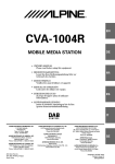
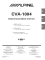
CVA-1004
MOBILE MULTIMEDIA STATION
FR
• OWNER'S MANUAL
Please read before using this equipment.
ES
• MODE D'EMPLOI
Veuillez lire avant d'utiliser cet appareil.
• MANUAL DE OPERACIÓN
Léalo antes de utilizar este equipo.
ES
IT
ALPINE ELECTRONICS MARKETING, INC.
1-1-8 Nishi Gotanda,
Shinagawa-ku,
Tokyo 141-0031, Japan
Phone 03-5496-8231
ALPINE ELECTRONICS OF AMERICA, INC.
19145 Gramercy Place, Torrance,
California 90501, U.S.A.
Phone 1-800-ALPINE-1 (1-800-257-4631)
ALPINE ELECTRONICS OF CANADA, INC.
7300 Warden Ave., Suite 203, Markham,
Ontario L3R 9Z6, Canada
Phone 1-800-ALPINE-1 (1-800-257-4631)
JEIL Moon Hwa Co.
18-6, 3Ga, Pil-dong, Jung-gu,
Seoul, Korea
ALPINE ELECTRONICS OF AUSTRALIA PTY. LTD.
6-8 Fiveways Boulevarde Keysborough,
Victoria 3173, Australia
Phone 03-9769-0000
ALPINE ELECTRONICS GmbH
Kreuzerkamp 7,
40878 Ratingen, Germany
Phone 02102-4550
ALPINE ELECTRONICS OF U.K. LTD.
Alpine House
Fletchamstead Highway, Coventry CV4 9TW, U.K.
Phone 0870-33 33 763
ALPINE ELECTRONICS FRANCE S.A.R.L.
(RCS PONTOISE B 338 101 280)
98, Rue de la Belle Etoile, Z.I. Paris Nord Il,
B.P. 50016, 95945 Roissy Charles de Gaulle
Cedex, France
Phone 01-48638989
ALPINE ITALIA S.p.A.
Viale C. Colombo 8, 20090 Trezzano Sul
Naviglio (MI), Italy
Phone 02-484781
ALPINE ELECTRONICS DE ESPAÑA, S.A.
Portal de Gamarra 36, Pabellón, 32
01013 Vitoria (Alava)-APDO 133, Spain
Phone 945-283588
Designed by ALPINE Japan
Printed in Korea (Y)
68P02294K65-O
SE
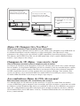
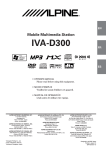
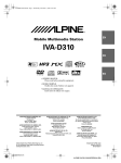
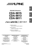
CD changer for CVA-1004.
Changeur CD pour CVA-1004.
Cambiador de CD para CVA-1004.
CD changer for CVA-1004.
Changeur CD pour CVA-1004.
Cambiador de CD para CVA-1004.
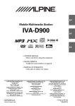
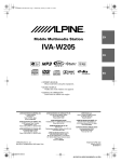
You cannot connect to CVA-1004.
Il est impossible de se raccorder au
CVA-1004.
No es posible conectarlo a CVA1004.
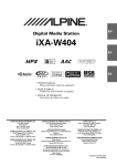
CHA-S634
CHA-1214
CHM-S630
Alpine CD Changers Give You More!
More musical selections, more versatility, more convenience.
An Alpine CD Changer adds more musical choices to your sound system. All models except CHM-S630 can
be controlled from Alpine head units and deliver excellent sound quality. The CHA-S634 is a highperformance 6-disc changer with a new M DAC, Ai-NET compatibility, Optical Digital Output, 150 Disc
Title Memory and CD TEXT. The CHA-1214 Ai-NET model holds 12 discs, and the CHM-S630 M-Bus
model is a super-compact 6-disc changer.
Changeurs de CD Alpine : vous avez le choix!
Plus de sélections musicales, plus de souplesse, plus de confort.
Un changeur de CD Alpine permet d'augmenter la plage des sélections musicales de votre système embarqué.
Tous les modèles, à l'exception du CHM-S630, peuvent être contrôlés à partir des autoradios Alpine et offrent
une excellente qualité audio. Le modèle CHA-S634 est un changeur 6 disques ultra performant compatible
Ai-NET et équipé d'un convertisseur N/A standard, d'une sortie optique numérique, d'une mémoire d'une
capacité de 150 titres et de la fonction CD TEXT. Le modèle CHA-1214 Ai-NET peut contenir 12 disques.
Le modèle CHM-S630 M-Bus est un changeur 6 disques super compact.
¡Los cambiadores Alpine de CD le ofrecen más!
Más selecciones musicales, más versatilidad y más ventajas.
Un cambiador Alpine de CD añade más opciones musicales a su equipo de sonido. Todos los modelos,
excepto el CHM-S630, pueden controlarse desde las unidades principales de Alpine y proporcionar un sonido
de calidad excepcional. El modelo CHA-S634 es un cambiador de 6 discos de alto rendimiento con el nuevo
DAC "M" y compatibilidad con Ai-NET, salida digital óptica, memoria de títulos de 150 discos y TEXTO
CD. El modelo CHA-1214 Ai-NET admite 12 discos y el modelo CHM-S630 Bus-M es un cambiador de 6
discos y tamaño reducido.
ENGLISH
Contents
Operating Instructions
WARNING
WARNING .................................................. 3
CAUTION ................................................... 3
PRECAUTIONS ......................................... 4
Basic Operation
CD/MP3/Changer Operation
(Optional)
Playing Optional CD player or Changer ......... 14
Repeat Play ..................................................... 14
M.I.X. (Random Play) .................................... 15
Scanning Programs ......................................... 15
Selecting Folders (concerning MP3) .............. 15
File/Folder Search (concerning MP3) ............. 16
Controlling CD Changer ................................. 16
Detaching the Front Panel ................................. 6
Attaching the Front Panel ................................. 6
Initial System Start-Up ..................................... 6
Turning Power On and Off ............................... 7
Raising the Monitor .......................................... 7
Lowering the Monitor ....................................... 7
Selecting the Monitor's Opening Position ........ 7
Adjusting the Monitor Viewing Angle .............. 8
Adjusting Volume/Balance (Between Left and
Right)/Fader (Between Front and Rear) ........ 8
Audio Mute Function ........................................ 8
Radio Operation
Manual Tuning .................................................. 9
Automatic Seek Tuning .................................... 9
Manual Storing of Station Presets .................... 9
Automatic Memory of Station Presets ............ 10
Tuning to Preset Stations ................................ 10
Selecting a Station from the List ..................... 10
XM Radio Operation (Optional)
Receiving the XM Channels with the XM
Receiver (Optional) ..................................... 11
Checking the XM Radio ID Number .............. 11
Changing the Channel Select Method ............ 12
Storing of XM Channel Presets ...................... 12
Receiving the Stored XM Channels ................ 12
Selecting a Channel by Category (Category
Tuning) ........................................................ 12
Displaying Category/Channel Name List ....... 13
Playing MP3 Files with the CD Changer ........ 17
Multi-Changer Selection ................................. 17
Setting the Range of MP3 File Selection ........ 17
DVD/Video CD/CD Player Operation
(Optional)
Playing DVD/Video CD/CD ........................... 18
Still/Pause ....................................................... 18
Chapter (DVD)/Track (Video CD) Sensor ...... 18
Fast Forward/Backward .................................. 19
Repeat Play ..................................................... 19
Controlling DVD Changer .............................. 19
Navigation System Operation
(Optional)
Turning on the Navigation Mode .................... 20
Interrupt Feature (NAV. MIX) ......................... 20
Interrupt Feature (NAV. MIX OUT) ............... 20
MobileHub™ Link Operation (Optional)
About MobileHub™ Link .............................. 21
Telephone Mode On and Off .......................... 21
Incoming Calls ................................................ 21
Calling ............................................................. 22
Calling by using the Speed Dial ................. 22
Calling by the Phone book ......................... 22
Calling by the outgoing history .................. 22
Calling by the incoming history ................. 23
Calling by the incoming missed call history .. 23
SMS (Short Message Service) Operation ....... 23
Setting the Call Receiving Method ................. 23
Changing the Display...................................... 13
1-EN
Other Useful Features
Simultaneous Operation .................................. 39
Displaying the Title/Text ................................. 24
Switching Display Mode ................................ 40
Titling Discs/Stations ...................................... 25
Operation with the Monitor Closed .................. 41
Erasing Disc Title/Station Title ....................... 26
Setting the Bass Control ................................. 26
Setting the Treble Control ............................... 27
Information
In Case of Difficulty ....................................... 42
Specifications .................................................. 44
Switching Phase .............................................. 28
Turning Loudness On and Off ........................ 28
Turning Defeat Mode On and Off ................... 28
Illumination Control ....................................... 29
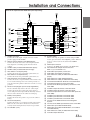
Installation and
Connections
Adjusting Brightness of Picture ...................... 29
Warning ........................................................... 45
Adjusting Color of Picture .............................. 30
Caution ............................................................ 45
Adjusting Tint of Picture ................................. 30
Precautions ...................................................... 45
Setting the Background Screen Color
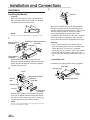
Installation ...................................................... 46
(DAY/NIGHT) ............................................. 31
Setting the Automatic Background
Screen Color ................................................ 31
Scroll Setting ................................................... 31
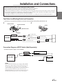
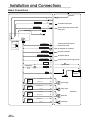
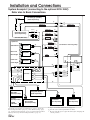
Basic Connections ........................................... 48
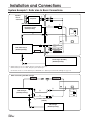
System Example 1 .......................................... 50
System Example 2
(connecting to the optional KCE-104V) ..... 52
Setting Automatic Opening/Closing of
Monitor ........................................................ 32
Turning Sound Guide Function On or Off ...... 32
Setting the Clock Display ............................... 33
Displaying Time .............................................. 33
Setting Time .................................................... 33
Adjusting Source Signal Levels ...................... 34
Setting the XM Auxiliary Data Field (ADF) .. 34
Subwoofer Control On and Off ....................... 34
Switching the Tuner Mode .............................. 35
Turning Mute Mode On and Off ..................... 35
Setting the External Expansion Box ............... 35
Rear Monitor Setting ...................................... 36
Setting the External Input ............................... 37
Setting Front/Rear/Subwoofer Preout of the
External Expansion Box .............................. 37
Displaying Spectrum Analyzer ....................... 38
Switching Disc Mode ...................................... 38
Operating an External Audio Processor
(Optional) .................................................... 38
2-EN
LIMITED WARRANTY
WARNING
WARNING
This symbol means important instructions.
Failure to heed them can result in serious
injury or death.
DO NOT BLOCK VENTS OR RADIATOR PANELS.
Doing so may cause heat to build up inside and may result
in fire.
DO NOT PLACE HANDS, FINGERS OR FOREIGN
OBJECTS IN INSERTION SLOTS OR GAPS.
INSTALL THE PRODUCT CORRECTLY SO THAT THE
DRIVER CANNOT WATCH TV/VIDEO UNLESS THE
VEHICLE IS STOPPED AND THE EMERGENCY BRAKE
IS APPLIED.
Doing so may result in personal injury or damage to the
product.
It is dangerous (and illegal in many states) for the driver to
watch TV/Video while driving a vehicle. Installing this
product incorrectly enables the driver to watch TV/Video
while driving. This may cause a distraction, preventing the
driver from looking ahead, thus causing an accident. The
driver or other people could be severely injured.
Swallowing them may result in serious injury. If
swallowed, consult a physician immediately.
KEEP SMALL OBJECTS SUCH AS BATTERIES OUT
OF THE REACH OF CHILDREN.
USE ONLY IN CARS WITH A 12 VOLT NEGATIVE
GROUND.
(Check with your dealer if you are not sure.) Failure to do
so may result in fire, etc.
DO NOT WATCH VIDEO WHILE DRIVING.
Watching the video may distract the driver from looking
ahead of the vehicle and cause an accident.
DO NOT OPERATE ANY FUNCTION THAT TAKES
YOUR ATTENTION AWAY FROM SAFELY DRIVING
YOUR VEHICLE.
Any function that requires your prolonged attention
should only be performed after coming to a complete stop.
Always stop the vehicle in a safe location before
performing these functions. Failure to do so may result in
an accident.
CAUTION
This symbol means important instructions.
Failure to heed them can result in injury or
material property damage.
HALT USE IMMEDIATELY IF A PROBLEM APPEARS.
Failure to do so may cause personal injury or damage to
the product. Return it to your authorized Alpine dealer or
the nearest Alpine Service Center for repairing.
Failure to do so may result in an accident.
KEEP FINGERS AWAY WHILE THE MOTORIZED
FRONT PANEL OR MOVING MONITOR IS IN
MOTION.
MINIMIZE DISPLAY VIEWING WHILE DRIVING.
Failure to do so may result in personal injury or damage to
the product.
KEEP THE VOLUME AT A LEVEL WHERE YOU CAN
STILL HEAR OUTSIDE NOISE WHILE DRIVING.
Viewing the display may distract the driver from looking
ahead of the vehicle and cause an accident.
DO NOT DISASSEMBLE OR ALTER.
Doing so may result in an accident, fire or electric shock.
USE THIS PRODUCT FOR MOBILE 12V
APPLICATIONS.
Use for other than its designed application may result in
fire, electric shock or other injury.
USE THE CORRECT AMPERE RATING WHEN
REPLACING FUSES.
Failure to do so may result in fire or electric shock.
3-EN
WARNING
PRECAUTIONS
Temperature
Be sure the temperature inside the vehicle is between
+45°C (+113°F) and 0°C (+32°F) before turning your unit
on.
Maintenance
If you have problems, do not attempt to repair the unit
yourself. Return it to your Alpine dealer or the nearest
Alpine Service Station for servicing.
Installation Location
Make sure the CVA-1004 will not be installed in a
location subjected to:
•
•
•
•
Direct sun and heat
High humidity and water
Excessive dust
Excessive vibrations
Handling the Detachable Front Panel
• Do not expose to rain or water.
• Do not drop or apply shock.
4-EN
Operation of some of the functions of this unit is very
complex. Because of this, it was deemed necessary to
place these functions into a special screen. This will
restrict operation of these functions to times when the
vehicle is parked. This ensures the focus of the driver's
attention will be on the road and not on the CVA-1004.
This has been done for the safety of the driver and
passengers.
The Title Input and SETUP screens cannot be made while
the car is moving. The car must be parked and the parking
brake must be engaged for the procedure described in the
Owner's Manual to be valid. These operations are not
possible while you are driving. Also if you attempt to
drive during operation, the display will show the warning
“CAN’T OPERATE WHILE DRIVING” for 5 seconds
and then the operation mode will be canceled.
This operation is the same as when selecting sources
using the remote control. When the car is parked, the
selection is made as described in the Owner's Manual.
Alpine products equipped with the Ai-NET bus,
connected to the CVA-1004, can be operated from the
CVA-1004. Depending on the products connected, the
functions and displays will vary. For details, consult your
Alpine dealer.
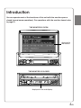
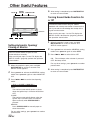
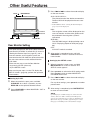
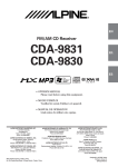
Introduction
You can operate most of the functions of this unit with the monitor open or
closed (except some operations). For operations with the monitor closed, refer
to page 41.
THE MONITOR IS OPEN
displayed in
the monitor
THE MONITOR IS CLOSED
displayed in the sub-display
5-EN
Basic Operation
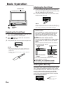
Attaching the Front Panel
OPEN/CLOSE
1
2
First, insert the right side of the front panel into
the main unit. Align the groove on the front panel
with the projections on the main unit.
Push the left side of the front panel until it locks
firmly into the main unit.
2
1
SOURCE/
PWR
Detaching the Front Panel
1
2
3
Press and hold SOURCE/PWR (Power) for more
than 2 seconds to turn off the power.
Press
(Release) at lower left side until the
front panel pops out.
Grasp the left side of the front panel and pull it out.
NOTES
• The front panel may become hot in normal usage
(especially the connector terminals), this is not a
malfunction.
• To protect the front panel, place it in the supplied
carrying case.
NOTE
Before attaching the front panel, make sure that there is
no dirt or dust on the connector terminals and no foreign
object between the front panel and the main unit.
[Compatibility with Factory Steering Wheel
Radio Controls
If your vehicle has steering wheel controls for
the radio, an optional steering wheel control
interface may be available to connect your
Alpine radio. For details, contact your Alpine
dealer.
[Controllable with Remote Control
This unit can be controlled with an optional Alpine
remote control. For details, consult your Alpine
dealer.
Point the optional remote control transmitter at
the remote control sensor.
Remote control
sensor
Remote control
sensor
When the monitor
is open.
When the monitor
is closed.
• You can use the remote control even when the
monitor display is closed.
[CVA-1004 is not compatible with MD,
cassette tapes and a 3-disc changer.
Initial System Start-Up
Immediately after installing or applying power to the
unit, it should be initialized. To do this, first, remove
the detachable front panel. Behind the front panel, to
the right of the connector, there is a small hole.
Using a pencil or other pointed object, press the
reset switch mounted behind this hole to complete
the initialization procedure.
RESET switch
6-EN
Basic Operation
Turning Power On and Off
Some of this unit's functions, cannot be performed
while the vehicle is in motion. Be sure to stop your
vehicle in a safe location and apply the parking
brake, before attempting these operations.
1
Raising the Monitor
1
NOTES
• The CVA-1004 is a precision device. With gentle
handling, its unique capabilities can be enjoyed for a
long time.
• If the monitor touches an obstacle while it is being
raised, the unit will stop raising the monitor
immediately. Should this occur, remove the obstacle
and press OPEN/CLOSE again to raise the monitor.
• When the movable monitor is opened, do not place any
object on the monitor and be careful not to bump or
apply any pressure to the monitor while it is open. This
can cause damage to the mechanism.
• Under low ambient temperature conditions, the
display may be dark for a short period of time
immediately after the power is turned on. Once the
LCD has warmed up, the display will return to
normal.
• For your safety, some operation of the unit cannot be
performed while the vehicle is in motion. In this case,
first stop the vehicle and engage the parking brake,
then perform the operation.
• If you select AUX or NAVI as the current source
without connecting to the CVA-1004, a noise may
occur when you open the monitor. This is not a
malfunction.
Press SOURCE/PWR (Power) to turn on the
unit.
The opening screen appears automatically on
the monitor.
NOTE
The unit can be turned on by pressing any other button
and TILT 7 8 .
except the OPEN/CLOSE, TITLE
The volume level gradually increases to the
previous level you were listening to before the
unit was turned off. Press and hold SOURCE/
PWR (Power) for at least 2 seconds to turn off
the unit.
NOTES
• After turning the system off, a slight ghost of the image
will remain temporarily. This is an effect peculiar to
LCD technology and is normal.
• Under cold temperature conditions, the screen may
lose contrast temporarily. After a short warm-up
period, it will return to normal.
• The CVA-1004 draws minimal current even when its
power switch is turned off. If the switched power
(ignition) lead of the CVA-1004 is connected directly
to the positive (+) post of the vehicle's battery, the
battery may be discharged. If this lead is unswitched,
it must be disconnected from the battery post should
the vehicle be left unused for an extended period of
time.
An SPST (Single-Pole, Single-Throw) switch (sold
separately) can be added to simplify this procedure.
Then, you can simply place it in the OFF position
when you leave the vehicle. Turn the SPST switch back
ON before using the CVA-1004. For connecting the
SPST switch, refer to "Connection Diagram of SPST
Switch" on page 47.
• Some operation of the unit cannot be performed while
the vehicle is in motion. In this case, be sure to first
stop your vehicle and apply the parking brake, then
perform the operation.
Press OPEN/CLOSE, or press and hold MUTE
on the optional Remote Control.
The unit beeps 3 times and raises the monitor
automatically.
Lowering the Monitor
1
Press OPEN/CLOSE, or press and hold MUTE
on the optional Remote Control.
The unit will beep 3 times and lower the monitor
automatically.
NOTES
• The CVA-1004 is a precision device. With gentle
handling, its unique capabilities can be enjoyed for a
long time.
• If the monitor touches an obstacle while it is being
lowered, the unit will stop lowering the monitor
immediately.
Should this occur, remove the obstacle and press
OPEN/CLOSE again to lower the monitor.
• If you select AUX or NAVI as the current source
without connecting to the CVA-1004, a noise may
occur when you close the monitor. This is not a
malfunction.
Selecting the Monitor's Opening
Position
The monitor's opening position has 2 settings.
1
Press and hold OPEN/CLOSE for at least 2
seconds while the monitor is being raised. Each
press changes the monitor position back or forth.
7-EN
Basic Operation
MUTE/SETUP
TILT 7 8
Adjusting Volume/Balance
(Between Left and Right)/Fader
(Between Front and Rear)
1
Press MODE (Rotary encoder) repeatedly to
choose the desired mode.
Each press changes the modes as follows:
→ NAV∗1 → SUB-W∗2 → BAL → FAD → VOL
Volume:
Balance:
Fader:
NAV.Level:
Subwoofer:
MODE (Rotary encoder)
NOTE
• If the Rotary encoder is not turned in 5 seconds after
selecting the BALANCE, FADER, NAV. Level or
SUBWOOFER mode, the unit automatically returns to
the VOLUME mode.
Adjusting the Monitor Viewing
Angle
∗1 When the SUBWOOFER mode is OFF (page 34), its
level cannot be adjusted.
∗2 When the NAV.MIX mode is OFF (page 20), its level
cannot be adjusted.
Adjust the monitor's angle for better visibility.
1
Press TILT 7 8 to adjust the monitor's angle so
the screen will be in the best viewing position.
Each press of the buttons produces a beep and
changes the screen angle between about 40 and
105 degrees.
When you press and hold 7 or 8 (TILT) for at
least 2 seconds, the monitor's angle keeps
moving until you release the button.
NOTES
• If the monitor touches an obstacle while the angle is
being adjusted the unit will stop the screen
immediately.
Should this happen, remove the obstacle and press
TILT 7 8 again.
• The screen color will vary when viewed at certain
angles. Adjust the screen angle for the best viewing
position.
• If the voltage of the vehicle's battery power is low, the
screen may blink when the screen angle is changed.
This is normal and not a malfunction.
CAUTION
Keep hands (or any other object) away from the display
while it is opening or closing to avoid damage or injury.
The back of the movable display will get very warm
under normal operating conditions. This is not a
malfunction. Do not touch.
8-EN
0~35
L15~R15
R15~F15
0~15
0~15
2
Turn MODE (Rotary encoder) until the desired
sound is obtained in each mode.
Audio Mute Function
Activating this function will instantly lower the
volume level by 20 dB.
1
Press MUTE/SETUP to activate the MUTE
mode. The audio level will decrease by about
20 dB.
Pressing MUTE/SETUP again will bring the
audio back to its previous level.
Radio Operation
Automatic Seek Tuning
SOURCE/
PWR
BAND/TEL.
1
2
Press SOURCE/PWR until a radio band and
frequency appears in the display.
Press BAND/TEL. repeatedly until the desired
radio band is displayed.
Each press changes the band:
→ FM1 → FM2 → AM
3
g
f TUNE/
A.ME
Preset buttons
(1 through 6)
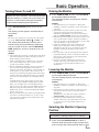
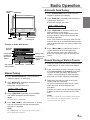
Example of Radio mode Screen
4
Selected
Source
Station Title
Preset button
number for
the stored
station
The current
Volume Level
setting status
Frequency of
the current
station
Current Time
1
Manual Tuning
2
Press SOURCE/PWR until a radio band and
frequency appears in the display.
Press BAND/TEL. repeatedly until the desired
radio band is displayed.
Each press changes the band:
→ FM1 → FM2 → AM
3
Press TUNE/A.ME repeatedly until "DX SEEK"
and "SEEK" disappear from the display.
NOTE
The initial mode is DX SEEK.
4
Press g or f to automatically seek for a
station downward or upward respectively.
The unit will stop at the next station it finds.
Press the same button again to seek the next
station.
Manual Storing of Station Presets
2
1
Press TUNE/A.ME to illuminate the DX and
SEEK indicators in the display.
With the DX (Distance) mode activated, both
strong and weak stations will be tuned in the
Auto-Seek operation.
Press again to return to the local mode. The DX
indicator will turn off and the SEEK indicator will
remain illuminated. Now, only strong stations will
be tuned.
3
Select the radio band and tune in a desired radio
station you wish to store in the preset memory.
Press and hold (for at least 2 seconds) any one
of the preset buttons (1 through 6), into which
you want to store the station. The selected
station is stored. The display shows the band,
preset No. and station frequency memorized.
Repeat the procedure to store up to 5 other
stations onto the same band.
To use this procedure for other bands, simply
select the band desired and repeat the
procedure.
A total of 18 stations can be stored in the preset
memory (6 stations for each band; FM1, FM2,
AM.)
NOTE
If you store a station in a preset memory which already
has a station, the current station will be cleared and
replaced with the new station.
Press g or f to move downward or upward
one step respectively until the desired station
frequency is displayed.
NOTE
The STEREO indicator appears on the monitor when a
Stereo FM station is tuned in.
9-EN
Radio Operation
SOURCE/
PWR
BAND/TEL. TUNE/A.ME
Tuning to Preset Stations
1
2
3
Press SOURCE/PWR to select the radio mode.
Press BAND/TEL. repeatedly until the desired
radio band is displayed.
Press the station preset button that has your
desired radio station in memory.
The display shows the band, preset No. and
frequency of the station selected.
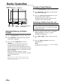
Selecting a Station from the List
g
f
Rotary
encoder
Station preset buttons
(1 through 6)
You can display the list of your titled stations (refer
to “Titling Discs/Stations” on page 25), and select
a station from this list.
Automatic Memory of Station
Presets
1
1
2
2
3
Press SOURCE/PWR to select the radio mode.
Press BAND/TEL. repeatedly until the desired
radio band is displayed.
Press and hold TUNE/A.ME for at least 2
seconds.
The frequency on the display continues to
change while the automatic memory is in
progress. The tuner will automatically seek and
store 6 strong stations in the selected band. They
will be stored into presets 1 to 6 buttons in order
of signal strength.
When the automatic memory has been
completed, the tuner goes to the station stored in
the preset location No. 1.
NOTE
If no stations are stored, the tuner will return to the
original station you were listening to before the auto
memory procedure began.
10-EN
3
When the monitor is open, press and hold the
Rotary encoder for at least 2 seconds.
The title list is displayed.
Press g or f to select a station from the
list.
Press the Rotary encoder to tune in the
selected station.
NOTE
To cancel the title list display, press and hold the Rotary
encoder for at least 2 seconds.
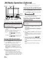
XM Radio Operation (Optional)
SOURCE/
PWR
BAND/TEL.
NOTES
• The controls on the CVA-1004 for XM Receiver
operation are operative only when an XM Receiver is
connected.
• The XM1, XM2 or XM3 band illuminates when in XM
mode.
1
2
Press SOURCE/PWR to select XM mode.
Press BAND/TEL. to select XM1, XM2 or XM3.
Each press changes the band:
→ XM1 → XM2 → XM3
g
3
f
Press g or f to select the desired channel.
Holding g or f will change channels
continuously.
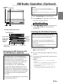
Example of XM mode Screen
Checking the XM Radio ID Number
Selected Source
Category Name
Channel
Name
Preset button
number for
the stored
station
The current
Volume Level
setting status
Channel
Number
Current Time
You need to provide XM with the unique XM
Radio ID number for your XM Radio Receiver in
order to subscribe to XM's programming.
This number is an 8 character alphanumeric
number that is printed on a label directly on the
XM Receiver.
It can also be displayed on the screen of the CVA1004 in the following way.
1
Receiving the XM Channels with
the XM Receiver (Optional)
XM Satellite Radio* is the next generation of
audio entertainment, with up to 100 brand-new
digital channels. For a small monthly fee,
subscribers can hear crystal-clear music, sports,
news and talk, coast-to-coast via satellite. For
more information, visit XM’s website at
www.xmradio.com or call 1-800-852-9696.
An optional XM Satellite Radio Receiver (TUAT021XM) with an optional XM Antenna may be
connected to the CVA-1004. With an XM Receiver
connected to the Ai-NET input of the CVA-1004,
the XM Receiver will be controllable from the
CVA-1004.
2
3
While receiving XM1/XM2/XM3, press g or
f to select channel “0.”
The unit alternately displays “RADIO ID” and the
number.
To cancel the ID number display, set the channel
to other than “0.”
NOTES
• You cannot use “O,” “S,”“ I,” or “F” for the ID
Number.
• You can check your ID number printed on the label on
the package of your XM Satellite Radio Receiver
(TUA-T021XM).
• Perform this operation after selecting “CH No.” in
“Changing the Channel Select Method” (page 12).
* XM and its corresponding logos are trademarks
of XM Satellite Radio Inc.
11-EN
XM Radio Operation (Optional)
NOTE
BAND/TEL.
TITLE
If you store a channel in a used preset memory, the current
channel will be cleared and replaced with the new one.
:/J
J
Receiving the Stored XM Channels
1
Press SOURCE/PWR to select the XM mode.
2
Press BAND/TEL. to select XM1, XM2 or XM3.
→ XM1 → XM2 → XM3
1 9/CAT
2 8/CAT
g f
SOURCE/PWR
Rotary
Preset buttons
encoder (1 through 6)
FUNC
Changing the Channel Select Method
There are 2 ways to select a channel: either by
channel number (numeric order) or by channel
name (alphabetical order).
1
J for at least 2
In XM mode, press and hold :/J
seconds.
Each press changes the display between “CH
No.” and “CH NAME” on the monitor.
CH No :
Arranging channels in numeric order.
Press g or f to find the desired
channel.
CH NAME : Arranging channels in alphabetical order.
Press g or f to find the desired
channel.
3
Press the channel preset button that has your
desired satellite channel in memory.
Selecting a Channel by Category
(Category Tuning)
Channels are divided into categories. Category
Tuning allows you to search for a specific channel
by its category.
1
In XM mode, press FUNC to select Category
Tuning mode.
The currently received category is displayed and
the “CATEGORY” (monitor) or “C” (sub-display)
indicator is lit.
2
Press 1 9/CAT or 2 8/CAT to select the desired
category.
The selected category is immediately received.
Holding the button will continuously change the
category.
3
1
2
Press SOURCE/PWR to select the XM mode.
To search for a channel, press g or f
while your selected category is displayed.
The channels within the category are displayed
in turn.
The selected channel is immediately received.
Press BAND/TEL. to select the desired band
(XM1, XM2 or XM3) you want to store.
NOTE
If no operation is performed within 13 seconds, or
FUNC is pressed, the unit returns to normal mode.
3
After tuning in the desired channel, press and
hold (for at least 2 seconds) any one of the
preset buttons (1 through 6) into which you
want to store the channel. The selected channel
is stored.
4
Repeat the procedure to store up to 5 other
channels onto the same band.
To use this procedure for other bands, simply
select the band desired and repeat the procedure.
A total of 18 channels can be stored in the preset
memory (6 channels for each band; XM1, XM2
and XM3).
Storing of XM Channel Presets
12-EN
XM Radio Operation (Optional)
Displaying Category/Channel
Name List
You can search for a channel while listening to the
currently received channel. Categories or channel
names are listed on the display to be selected.
1
When the monitor is opened in XM mode, press
and hold the rotary encoder for at least 2
seconds.
The Category or Channel Name list is displayed.
A triangle appears by the side of the currently
received channel or category.
NOTE
The previously displayed list (for category or channel
name) appears.
2
3
Press and hold :/J for at least 2 seconds to
switch the display between the Category list and
Channel Name list.
Press g or f to select the desired
category or channel.
When the Category list is displayed:
Select the desired category, and press and
hold :/J for at least 2 seconds. The Channel
Name list for the selected category is
displayed.
When the Channel Name list is displayed:
To select from other categories, press and
hold :/J for at least 2 seconds. The Category
list is displayed.
4
Press the rotary encoder to receive your
selected channel.
NOTES
• Press the rotary encoder for at least 2 seconds to
cancel displaying the list and return to normal mode.
• You can directly select the category while the Channel
Name list is displayed. Press FUNC to activate
Category Tuning mode, and then press 1 9/CAT or 2
8/CAT to select the category. The Channel Name list
of the selected category is displayed.
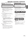
Changing the Display
Text information, such as the channel name, artist
name, and song/program title, is available with
each XM channel. The unit can display this text
information as explained below.
1
In XM mode, press TITLE .
Each time you press this button, the display
changes as shown below.
When the monitor is open: displayed in the
monitor
∗1
→ Channel Name → Song Title → XM
→ Auxiliary Data
Information
Category
Field (ADF)
Artist Name
∗2
∗1 Channel Name, Category, Song Title and Artist Name
are displayed.
∗2 Displayed when the XM ADF is set to ON (page 34).
To scroll to the next page, press and hold TITLE
for at least 2 seconds. When you select AUTO in
“Scroll Setting” (page 31), the page is switched every
30 seconds.
When the monitor is closed: displayed in the subdisplay
→ Channel Number → CLOCK → Channel Name
Auxiliary Data
Field (ADF)
∗3
← Song Title ← Artist Name ←
∗3 Displayed when the XM ADF is set to ON (page 34).
NOTES
• When The “Scroll Setting” (page31) is set to “AUTO,”
the display scrolls.
When the “Scroll Setting” is set to “MANUAL,” the
display scrolls only when you operate the unit
(POWER ON, BAND, etc., are displayed).
• “Channel Number” and “Clock” displays do not
scroll.
13-EN
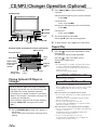
CD/MP3/Changer Operation (Optional)
2
SOURCE/PWR
Press g or f to select the desired
track(file).
Returning to the beginning of the current track(file) :
Press g.
Fast backward :
Press and hold g.
Advancing to the beginning of the next track(file) :
Press f.
1 9/FOLDER
Fast forward :
Press and hold f.
2 8/FOLDER
6(
g
f :/J
J 4(
)
5(
FUNC
)
)
CHG/R.SEL
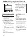
Example of MP3 compatible CD changer mode Screen
Song
Title
DISC number,
Folder number,
Track (file)
number
The current
setting status
Elapsed
playing
time
Volume
Level
Current Time
Playing Optional CD Player or
Changer
When an optional Alpine CD player or CD/MP3
changer is connected, you can control it from the
CVA-1004. This section describes operation
assuming that an Alpine CD player is connected.
(When a CD changer is connected, see page 16
to select your desired disc.)
You can directly select the CD Changer mode by
pressing CHG/R. SEL (changer) on the CVA1004.
1
Press SOURCE/PWR until the "CD" appears in
the display.
Insert a CD into the CD player, the player starts
playing.
14-EN
4
To pause playback, press :/J.
Pressing :/J again will resume playback.
To eject the disc, press eject on the CD player.
Repeat Play
1
MP3 indicator
Selected Source
Artist Name
3
Press 5 (
) to play back repeatedly the track
being played.
The track(file) will be played repeatedly.
Press 5 (
) again and select OFF to
deactivate the repeat play.
NOTES
• If a CD Changer or an MP3 compatible CD changer
is connected and the RPT (REPEAT) ALL mode is
selected, the unit repeatedly plays back all tracks on
the disc selected.
Displayed in the monitor display:
→ REPEAT → REPEAT ALL → (off)
Displayed in the sub-display:
→ RPT → RPT ALL → (off)
• When you select “FOLDER” in the “Setting the
Range of MP3 File Selection” section on page 17 and
set to REPEAT ALL, the Files will be repeatedly
played back.
When the monitor is open: displayed in the monitor
• In case a 6-disc CD changer or an MP3 compatible CD
changer is connected:
In CD changer mode, press FUNC to light the "FUNC"
indicator in red and go to step 1.
• In case a 12-disc CD changer is connected:
In changer mode, press FUNC twice to light the "FUNC"
indicator in red and go to step 1.
When the monitor is closed: displayed in the sub-display
• In case a 6-disc CD changer or an MP3 compatible CD
changer is connected:
In CD changer mode, press FUNC to illuminate the
"FUNC" indicator and go to step 1.
• In case a 12-disc CD changer is connected:
In changer mode, press FUNC twice to illuminate the
"FUNC" indicator and go to step 1.
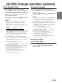
CD/MP3/Changer Operation (Optional)
M.I.X. (Random Play)
Scanning Programs
1
1
Press 4 (
) in the play or pause mode.
The tracks(files) on the disc will be played back
in a random sequence. After all the tracks on the
disc have been played back once, the player will
begin a new random sequence play until the
M.I.X. mode is canceled.
To cancel M.I.X. play, press 4 (
off the M.I.X.
To stop scanning, press 6 (
the Scan mode.
) and deactivate
NOTES
• When you select “FOLDER” in the “Setting the Range of
MP3 File Selection” (page 17), the first 10 seconds of
each file in the selected folder will be played back.
) again to turn
NOTES
• If a CD Changer equipped with the ALL M.I.X.
function is connected, ALL M.I.X. will also be
selectable.
In this mode, the tracks on all the CDs in the current
magazine will be included in the random playback
sequence.
→ M.I.X. → ALL M.I.X. → (off)
When the monitor is open: displayed in the monitor
• In case a 6-disc CD changer or an MP3 compatible CD
changer is connected:
In CD changer mode, press FUNC to light the "FUNC"
indicator in red and go to step 1.
• In case a 12-disc CD changer is connected:
In changer mode, press FUNC twice to light the "FUNC"
indicator in red and go to step 1.
When the monitor is closed: displayed in the sub-display
• In case a 6-disc CD changer is connected:
In CD changer mode, press FUNC to illuminate the
"FUNC" indicator and go to step 1.
• In case a 12-disc CD changer is connected:
In changer mode, press FUNC twice to illuminate the
"FUNC" indicator and go to step 1.
• When you select “FOLDER ONLY” in the “Setting the
Range of MP3 File Selection”(page 17), the files in
the selected folder are played back in random
sequence. After all the files have been played back,
play does not shift to the next folder.
When the monitor is open: displayed in the monitor
• In case a 6-disc CD changer or an MP3 compatible CD
changer is connected:
In CD changer mode, press FUNC to light the "FUNC"
indicator in red and go to step 1.
• In case a 12-disc CD changer is connected:
In changer mode, press FUNC twice to light the "FUNC"
indicator in red and go to step 1.
When the monitor is closed: displayed in the sub-display
• In case a 6-disc CD changer is connected:
In CD changer mode, press FUNC to illuminate the
"FUNC" indicator and go to step 1.
• In case a 12-disc CD changer is connected:
In changer mode, press FUNC twice to illuminate the
"FUNC" indicator and go to step 1.
Press 6 (
) to activate the Scan mode.
The first 10 seconds of each track will be played
back in succession.
Selecting Folders
(concerning MP3)
1
Press FUNC to illuminate the “FUNC” indicator,
and press 19/FOLDER or 28/FOLDER to
select the folder.
15-EN
CD/MP3/Changer Operation (Optional)
SOURCE/PWR
Disc select buttons
(1 through 6)
MUTE/SETUP
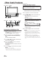
Controlling CD Changer
An optional 6-disc or 12-disc CD Changer may be
connected to the CVA-1004 if it is Ai-NET
compatible. With a CD Changer connected to the
Ai-NET input of the CVA-1004, the CD Changer
will be controllable from the CVA-1004.
Using the KCA-400C (the Multi-Changer
Switching device) or the KCA-410C (Versatile Link
Terminal) multiple changers can be controlled by
the CVA-1004.
See the “Multi-Changer Selection” (page 17) for
selecting the CD Changers.
BAND/TEL.
g f
:/J
J
Rotary
encoder
Preset 6
FUNC
File/Folder Search (concerning MP3)
NOTE
The controls on the CVA-1004 for CD Changer operation
are operative only when a CD Changer is connected.
1
You can select an MP3 file from the file/folder
name list and play back.
1
2
When the monitor is open in MP3 mode, press
and hold the Rotary encoder for at least 2
seconds during playback.
The unit switches to File/Folder Search mode,
and the file/folder name list is displayed.
Press g or f to select the desired file or
folder.
Press and hold -/J for at least 2 seconds to
select File Search or Folder Search.
When the folder name list is displayed:
If there are files in the folder, a triangle appears
by the side of each folder name.
Select the desired folder and press and hold
-/J for at least 2 seconds to display file name
list, and then press g or f to select the
desired file.
When the file name list is displayed:
To search for other folders containing desired
files, press and hold -/J for at least 2 seconds
to display the folder name list.
3
Press the Rotary encoder to execute the
setting.
The selected file, or the first file of the selected
folder starts to play.
NOTE
During search, press and hold the Rotary encoder for at
least 2 seconds to cancel the File Search mode.
16-EN
Press SOURCE/PWR to activate the CD
Changer mode. The display shows the disc
number and track number.
NOTES
• The source indicator varies depending on the
connected source.
• Press BAND/TEL. to switch the Disc mode in the CD/
Changer mode.
2
Press the disc select buttons (1 through 6)
corresponding to one of the discs loaded in the
CD Changer. The selected disc number appears
in the display and CD playback starts.
NOTES
• After selecting the desired disc, you can operate in the
same way as for the CD player.
For details, please see elsewhere in this section.
• When the “FUNC” indicator is lit in red in the
monitor, or is lit in the sub-display, the disc select
buttons become nonfunctional.
When a 12-disc CD Changer is connected:
To select discs numbered from 1 to 6, the
procedure is the same as for the 6-disc CD
Changer. To select discs numbered from 7 to 12,
first press FUNC. In the sub-display, this changes
the "D" indicator to "d." The "FUNC" indicator is
lit in yellow on the monitor. Then press the
desired disc select button. With FUNC activated,
the disc select buttons 1 to 6 will represent discs
7 to 12 respectively.
CD/MP3/Changer Operation (Optional)
Playing MP3 Files with the CD
Changer
4
NOTE
If an optional CD/DVD player is connected to the unit,
the disc mode can be switched each time you press
BAND/TEL. (see "Switching Disc Mode" on page 38.)
If you connect a changer compatible with MP3,
you can play CD-ROMs, CD-Rs, and CD-RWs
containing MP3 files.
1
2
3
Press SOURCE/PWR to switch to the CD
Changer mode.
Disc Number, Folder Number, File Number and
Elapsed Time are displayed.
Press any one of the disc select buttons (1
through 6) corresponding to one of the discs
loaded in the CD Changer.
To pause playback, press -/J.
Pressing -/J again will resume playback.
Multi-Changer Selection
Alpine's Ai-NET system will support up to 6 CD
Changers. When operating two or more changers,
the KCA-400C (Multi-Changer Switching device)
must be used. If you use 1 Switching device, you
can connect up to 4 CD Changers. If you use 2
Switching devices, you can connect up to 6 CD
Changers. When using KCA-410C (Versatile Link
Terminal), you can connect two changers and two
external outputs (AUX).
1
2
3
Setting the Range of MP3 File
Selection
When an MP3 compatible CD changer is
connected you can set the range of MP3 file
selection to “entire disc contents” or “folder
contents only.”
After carrying out steps 1 to 3 of “To display the
SETUP screen” (page 29), perform the operation
shown below.
1
2
3
When the monitor is open, press and hold
MUTE/SETUP for at least 2 seconds. The
SETUP screen appears.
Press preset 6 to activate the OTHER setting
mode. Press preset 6 again to select MP3 PLAY.
Press g or f to select ALL or FOLDER.
ALL :
plays all the files on one disc
FOLDER:
plays files in the selected folder only
Press SOURCE/PWR on the CVA-1004 to
activate the CD Changer mode.
Alternatively, press SOURCE on the Remote
Control to activate the CD Changer mode.
Proceed to step 3 below to select the desired CD
Changer.
To operate the selected changer, see elsewhere
in this section.
For any other settings, press preset 6 or another
preset button.
4
After setting is completed, press MUTE/SETUP
to return to normal mode.
Press BAND/TEL, or BAND on the Remote
Control, to activate the CD Changer Selection
mode.
The CD Changer Selection mode remains active
for 3 seconds after step 2 is performed. Press
BAND/TEL., or BAND on the Remote Control,
until the desired CD Changer indicator appears
on the display.
NOTE
If the selected CD Changer is not connected, the display
will show "NO CHANGER."
17-EN
DVD/Video CD/CD Player Operation (Optional)
Disc select buttons
(1 through 6)
SOURCE/PWR
NOTE
For automatic transmission vehicles, place the transmission
lever in the Park position.
Now, the locking system for the DVD mode
operation has been released. Unless the ignition key
is turned OFF, the DVD mode can be activated by
engaging only the parking brake. The steps above (1
through 3) are not necessary. Each time the ignition
key is turned OFF, the above steps must be
repeated.
NOTE
If you try to activate the DVD mode while driving, the
warning-PICTURE OFF FOR YOUR SAFETY will be
displayed in the monitor display.
g
J
f :/J
5(
)
FUNC CHG/R.SEL
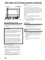
Playing DVD/Video CD/CD
If an optional Alpine DVD/video CD/CD player is
connected to the CVA-1004, you can control it from
the CVA-1004.
WARNING
It is dangerous (and illegal in many states) for the
driver to watch the TV/Video while driving the
vehicle. The driver may be distracted from looking
ahead and an accident could occur.
Install the CVA-1004 correctly so that the driver
cannot watch TV/Video unless the vehicle is
stopped and the emergency brake is applied.
If the CVA-1004 is not installed correctly, the
driver will be able to watch the TV/Video while
driving the vehicle and may be distracted from
looking ahead causing an accident. The driver or
other people could be severely injured.
To activate the DVD mode:
To watch a video source, your vehicle must be
parked with the ignition key in the ACC or ON
position. To do this, follow the procedure below.
1. Push the foot brake to bring your vehicle to a
complete stop at a safe location. Engage the
parking brake.
2. Keep pushing the foot brake and release the
parking brake once then engage it again.
3. While the parking brake is being engaged the
second time, release the foot brake.
18-EN
1
Press SOURCE/PWR to select the DVD mode.
Insert a disc into the DVD/video CD/CD player,
the player starts playing.
Still/Pause
1
Press :/J during DVD/video CD/CD play to
freeze frame or pause. To resume normal play,
press :/J for a second time.
Chapter (DVD)/Track (Video CD)
Sensor
1
Lightly press g or f during DVD/video
CD/CD play to return to the beginning of the
chapter/track being currently played or advance
to the beginning of the next chapter/track
respectively.
NOTE
The word "chapter or track" means a division of the
recorded picture/sound on a DVD/video CD/CD
respectively.
DVD/Video CD/CD Player Operation (Optional)
Fast Forward/Backward
1
Controlling DVD Changer
Press and hold g or f during play to fast
backward or forward respectively. Release the
button when you reach the desired portion you
wish to play. Playback starts from that portion.
You can directly select the DVD Changer mode by
pressing CHG/R.SEL (changer) on the CVA-1004.
Repeat Play
1
Press 5 (
) during play to repeatedly play the
chapter/track or title/disc being currently played.
Each press changes the repeat play as follows:
DVD:
→ Chapter
If an optional Alpine DVD Changer is connected
to the CVA-1004, the DVD Changer can be
controlled from the CVA-1004.
→ Title
(repeat play)
(repeat play)
→ Repeat Off
(normal play)
1
2
Press SOURCE/PWR. The "DVD Changer"
appears in the monitor.
“DVD CHG” is displayed in the sub-display.
Press the disc select buttons (1 through 6)
corresponding to one of the discs loaded in the
DVD changer.
Playback starts.
Video CD/CD:
→ Track
→ Disc
(repeat play)
→ Repeat Off
(repeat play) (video CD only)
NOTES
• The track/disc repeat modes cannot be used on video
CDs with playback control (PBC). Press "MENU" to
turn the PBC function off. For more details, see the
operating instructions of your DVD player or DVD
changer.
When the monitor is open: displayed in the monitor
• In case a 6-disc DVD changer is connected:
In DVD changer mode, press FUNC to light in red the
"FUNC" indicator and go to step 1.
When the monitor is closed: displayed in the sub- display
• In case a 6-disc DVD changer is connected:
In DVD changer mode, press FUNC to illuminate the
"FUNC" indicator and go to step 1.
NOTES
• After selecting the desired disc, you can operate in the
same may as for the DVD/Video CD/CD Player.
For details please see elsewhere in this section.
• When the “FUNC” indicator is lit in red in the
monitor, or is lit in the sub-display, the disc select
buttons become nonfunctional.
19-EN
Navigation System Operation (Optional)
3
SOURCE/
PWR
MUTE/SETUP
Press g or f to select ON or OFF.
ON: The volume level of the navigation system’s
voice guidance can be adjusted in 15 steps.
OFF:The navigation system’s voice guidance is
not output.
(For details about adjusting volume level, refer to
“Adjusting Volume/Balance/Fader” on page 8.)
For any other settings, press preset 5 or another
preset button.
4
g
f
NOTES
• The volume level of the audio will be automatically
reduced when the voice guidance of the Navigation
system starts.
• When the voice guidance of the Navigation system
starts to interrupt the audio, the display is
automatically changed to the navigation screen.
Preset 5
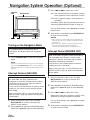
Turning on the Navigation Mode
If an optional Alpine Navigation System is
connected , The display shows the navigation
screen.
1
Press SOURCE/PWR to select the Navigation
mode.
NOTE
If the Navigation mode does not appear in the display
by pressing SOURCE/PWR, set the external setting of
NAV.IN to ON (refer to "Setting the External Input" on
page 37.)
Interrupt Feature (NAV. MIX)
With an Alpine navigation system connected to
the CVA-1004, the voice guidance of the
navigation system will be mixed with the radio or
CD audio, etc. You can also adjust the volume
level of the voice guidance.
If you use this unit connected to an external audio
processor, you cannot use this function (except
PXA-H700).
After carrying out steps 1 to 3 of "To display the
SETUP screen" (page 29), perform the operation
shown below.
1
2
When the monitor is open, press and hold
MUTE/SETUP for at least 2 seconds. The
SETUP screen appears.
Press preset 5 to activate the SYSTEM setting
mode. Press preset 5 again to select NAV. MIX.
20-EN
After setting is completed, press MUTE/SETUP
to return to normal mode.
Interrupt Feature(NAV.MIX OUT)
With an ALPINE navigation system connected to
the CVA-1004, the navigation system’s voice
guidance is mixed in and output from the Rear/
Subwoofer Output RCA connectors.
This function is not available when an external
audio processor is connected.
After carrying out steps 1 to 3 of “To display the
SETUP screen” (page 29), perform the operation
shown below.
1
2
3
When the monitor is open, press and hold
MUTE/SETUP for at least 2 seconds. The
SETUP screen appears.
Press preset 5 to activate the SYSTEM setting
mode. Press preset 5 again to select NAV.MIX
OUT.
Press g or f to select ON or OFF.
Select ON to allow the navigation system’s voice
guidance to interrupt the external amplifier.
For any other settings, press preset 5 or another
preset button.
4
After setting is completed, press MUTE/SETUP
to return to normal mode.
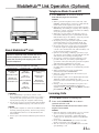
MobileHub™ Link Operation (Optional)
Telephone Mode On and Off
1
BAND/TEL.
NOTES
• When a portable telephone is not connected, “NO
PHONE” is displayed for at least 2 seconds, then the
mode returns to the original source mode.
• When the portable telephone is taken off the Junction
BOX during an incoming or outgoing call, or during a
hands-free call, the call will be treated as an ordinary
one by the portable telephone.
• When there is an incoming call while the power of
CVA-1004 is OFF, the power of CVA-1004 will turn
ON automatically for an ordinary call by the portable
telephone, but not for a hands-free call.
• Even if the power of the portable telephone is OFF,
when CVA-1004 is set to the telephone mode, the
power of the portable telephone will be turned ON.
• Even if the ACC power of the vehicle is turned OFF
(even if the engine is stopped) during a hands-free
call, the call is not disconnected, and an ordinary call
by the portable telephone is possible.
• If there is an incoming call during operation (except
an outgoing call or talking), operation mode will end
and switch to the incoming or talking mode.
• An outgoing call from a portable telephone is also
possible. However, you cannot perform different
operations at the same time from a portable telephone
and CVA-1004 as malfunction can result.
• With a Junction BOX connected, outgoing and
incoming history will also be recorded in the portable
telephone.
• While telephoning, the setting of CVA-1004
automatically turns to DEFEAT ON.
• When the call has finished, the unit returns to your
previous settings.
• The telephone volume can be adjusted from the CVA1004. The volume you set during the call is
memorized, and is automatically applied again on the
next call.
• During a call, you can send dial tone signals 1 to 6
using preset buttons 1 through 6, and dial tone
signals 7 to 9, 0, and by pressing FUNC, and then
preset buttons 1 through 6.
:/J
J
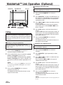
About MobileHub™ Link
Connect a separately sold Junction Box and a
portable telephone (available from Nokia) to
control the incoming and outgoing calls of the
portable telephone.
Functions that can be operated from CVA-1004
Incoming Calls
Outgoing Calls
Short Messages
Automatically
receive
Call out
(Speed Dial)
Display receiving
history
Manually receive
Call out
(phone book)
Display short
message
Call out (dialled)
Mail arrival
announcement
(information icon)
Missed call
announcement
(information icon)
Call out
(received)
Call out
(missed call)
CAUTION
• Even with hands-free operation, a driver can be
distracted during telephone operation or receiving a
call. For the sake of safety, drivers are requested to
refrain from operating the telephone while driving.
• For the sake of safety, operations other than incoming
calls and Speed-Dial outgoing calls cannot be used.
NOTES
• If a portable telephone is connected, its address book,
incoming and outgoing history, short message history
and standardized sentences are downloaded to the
Junction Box.
• Please refer to the instruction manual of the Junction
BOX.
Press BAND/TEL. for at least 2 seconds.
See relevant pages for each item.
Incoming Calls
1
2
Press -/J to receive an incoming call.
Press and hold BAND/TEL. for at least 2
seconds to finish a call.
The telephone mode will end and return to the
original source mode.
NOTES
• When the Automatic Calling mode is on, you can talk
after 3 seconds of receiving the incoming call.
• To switch between automatic calling and manual
calling, refer to "Setting the Call Receiving Method"
(page 23).
• Press and hold BAND/TEL. for at least 2 seconds
during an incoming call to disconnect it.
• You can call back by pressing :/J within 5 seconds
after finishing a call.
21-EN
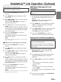
MobileHub™ Link Operation (Optional)
Calling by the Phone book
BAND/TEL.
g
MUTE/SETUP
f :/J
J
preset buttons
(1 through 6)
Preset 6
You can call up the Phone book registered in the
portable telephone to call from.
1
Press and hold BAND/TEL. for at least 2
seconds.
2
Press BAND/TEL. to select "PHONE BOOK" (on
the monitor) or "PHONE Bk"(on the sub-display).
The names in the phone book are displayed in
alphabetical order.
3
Press g or f to select the addressee from
the phone book.
To skip alphabetically to the next (or previous)
set of name, press and hold g or f for at
least 2 seconds.
4
Press :/J to place a call when the monitor is
closed.
Or press :/J twice when the monitor is open. At
the first press, the name and telephone number
of the addressee is displayed. Then the second
press places the call.
5
Press and hold BAND/TEL. for at least 2
seconds to end the call.
The telephone mode is canceled and returns to
the original source mode.
FUNC
Calling
The lists for Speed Dial, Phone Book, outgoing
history, incoming history and incoming missed call
history can be displayed. You can place a call by
these lists.
Calling by using the Speed Dial
You can place a call by retrieving one of the
telephone numbers registered in No. 1 to 9 of the
address book.
1
Press and hold BAND/TEL. for at least 2
seconds to display “SPEED DIAL.”
2
Press and hold (for at least 2 seconds) a preset
button (1 through 6) to place a call.
By pressing FUNC, and then pressing a preset
button (1 through 3) for at least 2 seconds, you
can place a call to the number registered in 7 to
9.
NOTE
You can place a call by pressing -/J after momentarily
pressing the preset button (1 through 6) of the number
you wish to call.
3
Press and hold BAND/TEL. for at least 2
seconds to end the call.
The telephone mode will end and return to the
original source mode.
Calling by the outgoing history
You can place a call to any of the last 999 dialed
calls recorded in memory.
1
Press and hold BAND/TEL. for at least 2
seconds.
2
Press BAND/TEL. again repeatedly to select
"DIALED."
3
Press g or f to select an addressee from
the outgoing history.
Press and hold g or f to change the
addressee continuously.
4
Press :/J to place a call when the monitor is
closed.
Or press :/J twice when the monitor is open. At
the first press, the name and telephone number
of the addressee is displayed. Then the second
press places the call.
5
Press and hold BAND/TEL. for at least 2
seconds to end the call.
The telephone mode will end and return to the
original source mode.
NOTE
You cannot use this function if there is not an outgoing history on
the unit.
22-EN
MobileHub™ Link Operation (Optional)
Calling by the incoming history
You can place a call to any of the last 999
received calls recorded in memory.
1
Press and hold BAND/TEL. for at least 2
seconds.
2
Press BAND/TEL. again repeatedly to select
"RECEIVED."
3
Press g or f to select an addressee from
the incoming history.
Press and hold g or f to change the
addressee continuously.
4
Press :/J to place a call when the monitor is
closed.
Or press :/J twice when the monitor is open. At
the first press, the name and telephone number
of the addressee is displayed. Then the second
press places the call.
5
Press and hold BAND/TEL. for at least 2
seconds to end the call.
The telephone mode will end and return to the
original source mode.
NOTE
You cannot use this function if there is not an incoming
history on the unit.
Calling by the incoming missed call history
SMS (Short Message Service)
Operation
You can receive short messages and display the
contents.
1
All received messages are indicated by an icon
(on the monitor) or “NEW MSG” (on the subdisplay).
When the monitor is open, press and hold
BAND/TEL. for at least 2 seconds.
2
Press BAND/TEL. again repeatedly until "SMS
INBOX" is indicated and the list of received
message is displayed.
3
Press g or f to select a message and then
press -/J to display the message content.
Press -/J again to return to the list.
4
Press and hold BAND/TEL. for at least 2
seconds to return to the original source mode.
Setting the Call Receiving Method
Connecting to the Junction Box is necessary to
set the call receiving method.
After carrying out steps 1 to 3 of “To display the
SETUP screen” (page 29), perform the operation
shown below.
1
Press and hold BAND/TEL. for at least 2
seconds.
2
Press BAND/TEL. again repeatedly to select
"MISSED."
1
Press g or f to select an addressee from
the absent incoming history.
Press and hold g or f to change the
addressee continuously.
2
3
4
5
Press :/J to place a call when the monitor is
closed.
Or press :/J twice when the monitor is open. At
the first press, the name and telephone number
of the addressee is displayed. Then the second
press places the call.
3
Press preset 6 to activate the OTHER setting
mode. Press preset 6 again to select TEL
RECEIVE.
Press g or f to select AUTO or MANUAL.
AUTO:
The incoming call is automatically accepted
after 3 seconds.
Press and hold BAND/TEL. for at least 2
seconds to end the call.
The telephone mode will end and return to the
original source mode.
NOTE
You cannot use this function if there is not an incoming
missed call history on the unit.
When the monitor is open, press and hold
MUTE/SETUP for at least 2 seconds. The
SETUP screen appears.
MANUAL:
The incoming call is manually accepted by
pressing -/J.
For any other settings, press preset 6 or another
preset button.
4
After setting is completed, press MUTE/SETUP
to return to normal mode.
23-EN
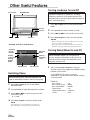
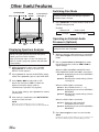
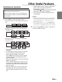
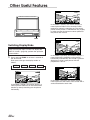
Other Useful Features
Radio mode:
The monitor is closed.
(displayed in the sub-display)
TITLE
↓
FREQUENCY DISPLAY
↓
CLOCK DISPLAY
↓
TITLE DISPLAY
CD mode:
The monitor is open.
(displayed in the monitor)
(Text is displayed for the CVA-1004 when a compatible
changer with CD text is connected.)
↓
TEXT DISPLAY (DISC/TRACK NAME)∗1
↓
TITLE DISPLAY
J
f :/J
g
CD mode:
The monitor is closed
(displayed in the sub-display).
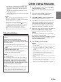
Displaying the Title/Text
It is possible to display the Disc/Station title if the
title has been previously inputted. For details, see
“Titling Discs/Stations” (page 25). Text information,
such as the disc name and the track name, will be
displayed if playing a CD text compatible disc. It is
also possible to display the folder name, the file
name, and the tag, etc. while playing MP3 files.
1
Press TITLE .
The mode will change every time the button is
pressed.
About “Title” and “Text”
Title: With this device, it is possible to input the Disc/
Station name (refer to page 25). This inputted
name is referred to as a “title.”
You cannot input or display titles on MP3 discs.
Text: Text compatible CDs contain text information such
as the disc name and track name. Such text
information is referred to as “text.”
↓
TRACK No./ELAPSED TIME DISPLAY
↓
CLOCK DISPLAY
↓
TEXT DISPLAY (DISC NAME)∗1
↓
TEXT DISPLAY (TRACK NAME)∗1
↓
TITLE DISPLAY
MP3 mode:
The monitor is open.
(displayed in the monitor)
(MP3 files can be played back with the CVA-1004 if an MP3
compatible changer is connected.)
↓
TAG (TRACK/ALBUM/ARTIST NAME) DISPLAY∗2
↓
FILE/FOLDER NAME DISPLAY
↓
FRAME DISPLAY∗3
↓
TITLE DISPLAY
MP3 mode:
The monitor is closed.
(displayed in the sub-display)
↓
TRACK No./ELAPSED TIME DISPLAY
↓
CLOCK DISPLAY
↓
TAG (TRACK/ALBUM/ARTIST NAME) DISPLAY∗2
↓
FOLDER NAME DISPLAY
↓
FILE NAME DISPLAY
↓
FRAME DISPLAY∗3
↓
TITLE DISPLAY
CD text disc mark indicates that the CD has text
data.
However, some characters may not be displayed
correctly.
Radio mode:
The monitor is open.
(displayed in the monitor)
TITLE DISPLAY
∗1
Displayed during playback of a disc with CD Text.
When the CD contains no Text data, the
monitor display will be blank or the submonitor will display “_ _ _ _ _ _ _ _.”
24-EN
Other Useful Features
∗2
∗3
If an MP3 file contains ID3 tag information, all the
ID3 tag information is displayed (e.g., track name,
artist name, or album name). All other tag data is
ignored.
“NO TAG” will be displayed if an MP3 file contains
no ID3 tag information.
The recording sampling rate and bit rate of the MP3
file are displayed.
NOTES
• Some characters may not be displayed correctly with
this device, depending on the character type.
• The CD changer must also be CD Text compatible for
the Text information to be displayed.
• When the Scroll Setting (refer to page 31) is set to
for at least 2
“MANUAL”, press and hold TITLE
seconds to scroll the Text information, etc., only once.
• "NO SUPPORT" is displayed when the desired text
information cannot be displayed on this unit.
• If the title was not previously input, the monitor
display will be blank or the sub-monitor will display
“_ _ _ _ _ _ _ _.”
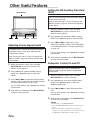
1
2
3
4
5
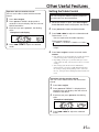
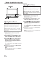
Titling Discs/Stations
1. Push the foot brake to bring your vehicle to a
complete stop at a safe location. Engage the parking
brake.
2. Keep pushing the foot brake and release the parking
brake once then engage it again.
3. While the parking brake is being engaged the
second time, release the foot brake.
NOTE
For automatic transmission vehicles, place the transmission
lever in the Park position.
Now, the locking system for the Title display mode has
been released. Unless the ignition key is turned OFF,
the Title display mode can be activated by engaging
only the parking brake. The steps above (1 through 3)
are not necessary. Each time the ignition key is turned
OFF, the above steps must be repeated.
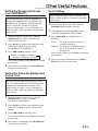
Press and hold the TITLE
for at least 2
seconds. The first character will blink.
Press g or f to select the desired letter/
numeral/symbol available for naming.
Press -/J to store the first character. The first
character will stop blinking and the display will
automatically advance to the next character.
When that character begins to blink, you may
choose the next letter or symbol of your title.
Repeat the steps 3 and 4 above to complete the
titling. Pressing -/J after entering the 8th
character, automatically stores the title into
memory.
When entering a title of less than 8 characters
(for example, 3 character title):
After entering 3 characters to complete your title,
the 4th character space will be blinking. Go to
step 6 to complete the title.
It is possible to title your favorite discs or radio
stations.
To activate the Title display mode:
To title a disc, your vehicle must be parked with the
ignition key in the ACC or ON position. To do this, follow
the procedure below.
When the monitor is open, press TITLE
and
select the title display mode.
For details, see “Displaying the Title/Text” (page
24).
6
Press TITLE
to record the title.
NOTES
• If you cancel while entering a title, selected characters
are not written.
• You can enter 24 radio station titles on this unit. If you
try to store beyond the limit, the display will show
“MEMORY FULL” At this point, no more titles can be
stored.
• The CD/DVD player or Changer memory capacity
varies depending upon the model being used.
• To input a new title, one of the previously inputted
titles must first be deleted.
• When you want to erase a title, enter a space into all
spaces.
• The operations described in steps 3 to 5 must be made
within 10 seconds. The input mode will be canceled if
no action is taken for over 10 seconds.
• Removing power from the unit may delete station
titles. Use caution when manipulating the power cord.
NOTE
You cannot title discs/stations while you are driving. If you
attempt to drive while titling, the display will show the
warning “CAN’T OPERATE WHILE DRIVING” for 5
seconds and then the unit will return to normal mode.
25-EN
Other Useful Features
bass engine
Setting the Bass Control
TITLE
You can change the Bass Frequency emphasis to
create your own tonal preference.
1
Preset 1
Preset 2
g
bass engine
g
f :/J
J
TITLE
f
Preset 1
2
3
4
5
Within 10 seconds, press and hold -/J for at
least 2 seconds to activate the title scanning
mode.
The title in the display will blink.
Press g or f repeatedly until the title you
want to erase is displayed.
Press and hold -/J for at least 2 seconds to
display “DELETE TITLE.”
Press -/J again within 10 seconds to erase the
selected title.
Press TITLE
to cancel the title erasing mode.
NOTES
• You cannot erase CD-TEXT.
• When no title is input, “NO DATA” is displayed and
then the unit returns to the disc/station titling mode.
26-EN
Press g or f to adjust the selected mode.
• Bass Level : -7~+7
You can emphasize or weaken the bass
frequency.
• Bass center frequency :
→ 60Hz ↔ 70Hz ↔ 80Hz ↔ 90Hz ↔ 100Hz ↔ 130Hz ↔ 150Hz ↔ 200Hz ←
Changes the displayed frequency's band width
to wide or narrow.
:/J
J
When the monitor is open, press
TITLE
to select the titling mode. Then, press
for at least 2 seconds.
and hold TITLE
Press preset 1 to select the desired mode.
Emphasizes the displayed Bass frequency
ranges.
• Bass Band Width (Q-Factor):
→ WIDE1 ↔ WIDE2 ↔ WIDE3 ↔ WIDE4 ←
(Narrow)←..............................→ (Wide)
Preset 2
Erasing Disc Title/Station Title
1
2
3
When the monitor is open, press bass engine.
BASS ENGINE mode is displayed in the monitor.
4
Press bass engine to return to normal mode.
NOTES
• If no buttons are pressed within 10 seconds, the Bass
control setting will be turned off automatically.
• Depending on the type of external audio processors
connected to the unit, you may not be able to set some
settings.
• The settings of the Bass will be individually
memorized for each source (FM, AM and CD) until
the setting is changed. Depending on the connected
devices, some functions and display indications do not
work.
Other Useful Features
Operation with the monitor closed
You can set the Bass control with the monitor
closed.
1
2
3
Press bass engine.
Setting the Treble Control
You can change the Treble Frequency emphasis
to create your own tonal preference.
Press preset 1. BASS is displayed for 2
seconds in the sub-display, then the value of
BASS Level blinks.
1
Each time you press preset 1, the blinking
shifts.
Example of sub-display
2
3
When the monitor is open, press bass engine.
BASS ENGINE mode is displayed in the monitor.
Press preset 2 to select the desired mode.
Press g or f to adjust the selected mode.
Treble Level : -7~+7
You can emphasize the treble frequency.
4
Treble center frequency:
→ 10.0kHz ↔ 12.5kHz ↔ 15.0kHz ↔ 17.5kHz ←
Press g or f to adjust the selected
mode.
Emphasizes the displayed Treble frequency
ranges.
4
Press bass engine to return to normal mode.
NOTES
• If no buttons are pressed within 10 seconds, the Treble
control setting will be turned off automatically.
• Depending on the type of external audio processors
connected to the unit, you may not be able to set some
settings.
• The settings of the Treble will be individually
memorized for each source (FM, AM and CD) until
the setting is changed. Depending on the connected
devices, some functions and display indications do not
work.
Operation with the monitor closed
You can set the Treble control with the monitor
closed.
1
2
3
4
Press bass engine.
Press preset 2. TREBLE is displayed for 2
seconds in the sub-display, then the value of
TREBLE Level blinks.
Each time you press preset 2, the blinking
shifts.
Example of sub-display
Press g or f to adjust the selected
mode.
27-EN
Other Useful Features
Turning Loudness On and Off
bass engine
MUTE/SETUP
Loudness introduces a special low- and highfrequency emphasis at low listening levels. This
compensates for the ear's decreased sensitivity to
bass and treble sound.
1
Press bass engine to turn on the BASS ENGINE
mode.
Preset 1
Preset 3
g
f
Preset 4
2
3
4
Selected
Mode
Setting/
Adjusting
status
Setting
items of the
Display
Setting
Mode
Volume Level
Current Time
Switching Phase
Before switching Phase, select the Subwoofer ON
(refer to "Subwoofer Control On and Off" on page 34).
1
2
3
4
Press bass engine to turn on the BASS
ENGINE mode.
Press preset 3 to select Subwoofer Phase mode.
Press g or f to switch the phase of the
subwoofer output.
0° ↔ 180°
Press bass engine to return to normal mode.
NOTE
If no buttons are pressed within 10 seconds, the
Switching Phase setting will be off automatically.
28-EN
Press g or f to set LOUD to ON or OFF.
Press bass engine to return to normal mode.
NOTES
• When connecting an external audio processor to the
unit, you cannot use this function.
• If no operation is performed within 10 seconds, the
Loudness setting will be turned off automatically.
Example of SETUP. mode Screen
Selected
Preset
Number
Press preset 4 to select Loudness mode.
Turning Defeat Mode On and Off
When the defeat mode is on, the processor
circuits are bypassed and the audio signals go
directly to the line output. The equalizer curve,
therefore, becomes flat.
1
Press and hold bass engine for at least 2
seconds. Each press toggles the DEFEAT setting
between ON and OFF.
In the DEFEAT ON mode, any current
adjustments are returned to their default settings
as shown below.
DEFAULT:
Bass Level
Bass Center Freq.
Bass Band Width
Treble Level
Treble Center Freq.
LOUD
:
:
:
:
:
:
±0
80 Hz
WIDE1
±0
10.0 kHz
OFF
Other Useful Features
Illumination Control
To display the SETUP screen:
To display the Setup screen, your vehicle must be
parked with the ignition key in the ACC or ON
position. To do this, follow the procedure below.
1. Push the foot brake to bring your vehicle to a
complete stop at a safe location. Engage the
parking brake.
2. Keep pushing the foot brake and release the
parking brake once then engage it again.
3. While the parking brake is being engaged the
second time, release the foot brake.
Adjusting Brightness of Picture
After carrying out steps 1 to 3 of "To display the
SETUP screen" (described on this page), perform
the operation shown below.
1
2
3
NOTE
For automatic transmission vehicles, place the
transmission lever in the Park position.
Now, the locking system for the SETUP screen
operation has been released. Unless the ignition
key is turned OFF, the SETUP screen can be
activated by engaging only the parking brake. The
steps above (1 through 3) are not necessary.
Each time the ignition key is turned OFF, the
above steps must be repeated.
1
2
3
When the monitor is open, press and hold
MUTE/SETUP for at least 2 seconds. The
SETUP screen appears.
Press preset 1 to activate the DISPLAY setting
mode. Press preset 1 again to select BRIGHT.
Press g or f to make the picture darker or
brighter. You can adjust the brightness between
MIN (–16) and MAX (+16). When it reaches the
minimum or maximum point, the display shows
"MIN" or "MAX" respectively.
For any other settings, press preset 1 or another
preset button.
4
After setting is completed, press MUTE/SETUP
to return to normal mode.
NOTE
The Brightness settings for the video sources (AUX/DVD/
NAV.) will be individually memorized.
When the monitor is open, press and hold
MUTE/SETUP for at least 2 seconds. The
SETUP screen appears.
Press preset 1 to activate the DISPLAY setting
mode. Press preset 1 again to select DIMMER.
Press g or f to set the Illumination control.
AUTO: In the Auto Dimmer mode, the
backlighting of the monitor is dimmed
when the instrument panel lighting of the
vehicle is turned on (the dimmer input
lead must be connected.)
ON:
Deactivate the Auto Dimmer mode and
keep the backlighting low.
OFF:
Keep the backlighting of the monitor
bright.
For any other settings, press preset 1 or another
preset button.
4
After setting is completed, press MUTE/SETUP
to return to normal mode.
29-EN
Other Useful Features
Adjusting Tint of Picture
MUTE/SETUP
Tint adjustment can be made only to video
sources (DVD, Navigation system, etc).
Tint adjustment cannot be made if a Navigation
system with the RGB feature is connected.
After carrying out steps 1 to 3 of "To display the
SETUP screen" (page 29), perform the operation
shown below.
Preset 1
Preset 2
g
f
Adjusting Color of Picture
1
2
3
Color adjustment can be made only to video
sources (DVD, Navigation system, etc). Color
adjustment cannot be made if a Navigation
system with the RGB feature is connected.
After carrying out steps 1 to 3 of "To display the
SETUP screen" (page 29), perform the operation
shown below.
1
2
3
When the monitor is open, press and hold
MUTE/SETUP for at least 2 seconds. The
SETUP screen appears.
Press preset 1 to activate the DISPLAY setting
mode. Press preset 1 again to select COLOR.
Press g or f to adjust the color between
MIN (-16) and MAX (+16) until you get your
desired color. When it reaches the minimum or
maximum point, the display shows “MIN” or
“MAX” respectively.
For any other settings, press preset 1 or another
preset button.
4
After setting is completed, press MUTE/SETUP
to return to normal mode.
NOTE
The Color setting for the video sources (AUX/DVD/NAV.)
will be individually memorized.
30-EN
When the monitor is open, press and hold
MUTE/SETUP for at least 2 seconds. The
SETUP screen appears.
Press preset 1 to activate the DISPLAY setting
mode. Press preset 1 again to select TINT.
Press g or f to adjust the Tint (between –
16 and +16). When it reaches the minimum or
maximum point, display shows "R MAX" or "G
MAX" respectively.
For any other settings, press preset 1 or another
preset button.
4
After setting is completed, press MUTE/SETUP
to return to normal mode.
NOTE
The TINT setting for the video sources (AUX/DVD/NAV.)
will be individually memorized.
Other Useful Features
Setting the Background Screen
Color (DAY/NIGHT)
The background color can be set differently for
daytime use (DIMMER OFF) and nighttime use
(DIMMER ON). (For details of Dimmer ON/OFF,
refer to “Illumination Control” on page 29.)
After carrying out steps 1 to 3 of “To display the
SETUP screen” (page 29), perform the operation
shown below.
1
2
3
When the monitor is open, press and hold
MUTE/SETUP for at least 2 seconds. The
SETUP screen appears.
Scroll Setting
After carrying out steps 1 to 3 of "To display the
SETUP screen" (page 29), perform the operation
shown below.
1
2
3
For any other settings, press preset 1 or another
preset button.
→ BLUE-1 → GREEN-1 → GRAY-1
4
Press g or f and select AUTO or
MANUAL.
The display of CD text, title, etc., is
scrolled continuously.
MANUAL: The display is scrolled only when a
disc is loaded or when a track is
changed, etc.
Press g or f to select the color.
For any other settings, press preset 1 or another
preset button.
Press preset 2 to select GENERAL Setting
mode. Press preset 2 to select SCROLL.
AUTO:
Press preset 1 to activate the DISPLAY setting
mode. Press preset 1 again to select
B.GND(DAY) or B.GND(NIGHT).
GRAY-2← GREEN-2 ← BLUE-2 ←
When the monitor is open, press and hold
MUTE/SETUP for at least 2 seconds.
4
When the setting is completed, press MUTE/
SETUP to return to normal mode.
After setting is completed, press MUTE/SETUP
to return to normal mode.
Setting the Automatic Background
Screen Color
When the Auto Background Screen Color is set to
ON, turning the ignition key on and off changes the
background screen color to blue, green or gray.
After carrying out steps 1 to 3 of “To display the
SETUP screen” (page 29), perform the operation
shown below.
1
2
3
When the monitor is open, press and hold
MUTE/SETUP for at least 2 seconds.
The SETUP screen appears.
Press preset 1 to activate the DISPLAY setting
mode. Press preset 1 again to select AUTO
B.GND.
Press g or f to set ON or OFF.
For any other settings, press preset 1 or another
preset button.
4
After setting is completed, press MUTE/SETUP
to return to normal mode.
31-EN
Other Useful Features
TITLE
4
MUTE/
SETUP OPEN/CLOSE
After setting is completed, press MUTE/SETUP
to return to normal mode.
Turning Sound Guide Function On
or Off
Preset 2
g
f -/J
J
The Sound Guide function will give audible
feedback with a beep sound when a button on the
unit is pressed to acknowledge the receipt of the
signal from the button.
After carrying out steps 1 to 3 of "To display the
SETUP screen" described on (page 29), perform
the operation shown below.
1
Setting Automatic Opening/
Closing of Monitor
You can set the monitor to open or close
automatically or manually.
2
3
After carrying out steps 1 to 3 of "To display the
SETUP screen" (page 29), perform the operation
shown below.
1
2
3
When the monitor is open, press and hold
MUTE/SETUP for at least 2 seconds. The
SETUP screen appears.
Press preset 2 to activate the GENERAL setting
mode. Press preset 2 again to select MONITOR
O/C.
Press g or f to set the Auto Opening
mode.
→ FULL ↔ CLOSE ↔ MANUAL ←
FULL:
The monitor automatically opens or closes
when the ignition key is turned to ACC/ON or
OFF.
CLOSE:
The monitor automatically closes when the
ignition key is turned to OFF. The monitor
opens manually when OPEN/CLOSE is
pressed.
MANUAL:
Press OPEN/CLOSE to manually open or
close the monitor.
For any other settings, press preset 2 or another
preset button.
32-EN
When the monitor is open, press and hold
MUTE/SETUP for at least 2 seconds. The
SETUP screen appears.
Press preset 2 to activate the GENERAL setting
mode. Press preset 2 again to select BEEP.
Press g or f to select ON or OFF.
ON: The unit beeps when a button is pressed.
OFF: No beep sound.
For any other settings, press preset 2 or another
preset button.
4
After setting is completed, press MUTE/SETUP
to return to normal mode.
Other Useful Features
Setting the Clock Display
After carrying out steps 1 to 3 of "To display the
SETUP screen" (page 29), perform the operation
shown below.
1
2
3
When the monitor is open, press and hold
MUTE/SETUP for at least 2 seconds. The
SETUP screen appears.
Press preset 2 to select GENERAL setting
mode. Press preset 2 again to select CLOCK
DISP.
Press g or f to turn ON or OFF the clock
display on the monitor.
For any other settings, press preset 2 or another
preset button.
4
Setting Time
After carrying out steps 1 to 3 of "To display the
SETUP screen" (page 29), perform the operation
shown below.
1
2
3
4
After setting is completed, press MUTE/SETUP
to return to normal mode.
When the monitor is closed, press
TITLE
repeatedly until the clock time is
displayed in the sub-display.
NOTES
• Selecting any function while in the clock priority mode
will interrupt the time display momentarily. The
function selected will be displayed for about 5 seconds
before the time returns to the display.
• The clock time is not shown on both the monitor and
the sub-display simultaneously.
Press preset 2 to activate GENERAL setting
mode. Press preset 2 again to select CLOCK
ADJ., then press -/J or g/ f to appear
the clock adjusting menu.
Press preset 2 to select HOUR. Then press g
or f to adjust the hour.
Press preset 2 to select MINUTE. Then press
g or f to adjust the minutes.
To quickly set the time to the nearest hour, press
preset 2 to select MINUTE ZERO, then press
-/J or g/ f.
If the minutes is ":30" or under, the hour is the
current number. If the minutes is more than ":30",
or If you set the minute to "00", the hour is
moved up.
Displaying Time
1
When the monitor is open, press and hold
MUTE/SETUP for at least 2 seconds. The
SETUP screen appears.
To return to the previous mode, press preset 2
to select RETURN, then press -/J, g or
f.
5
After setting is completed, press MUTE/SETUP
to return to normal mode.
33-EN
Other Useful Features
Setting the XM Auxiliary Data Field
(ADF)
MUTE/SETUP
You can set the Auxiliary Data Field (ADF) display
of the received channel.
After carrying out steps 1 to 3 of “To display the
SETUP screen” (page 29), perform the operation
shown below.
1
g
f
Preset 4
Preset 5
2
3
Adjusting Source Signal Levels
1
2
3
When the monitor is open, press and hold
MUTE/SETUP for at least 2 seconds. The
SETUP screen appears.
Press preset 4 to select the RADIO setting
mode. Press preset 4 again to select FM
LEVEL.
Press g or f to select the FM signal level
HIGH or LOW to make the signal levels between
the FM band and other sources closer.
For any other settings, press preset 4 or another
preset button.
4
Press preset 4 to activate the RADIO setting
mode. Press preset 4 again to select XM ADF.
Press g or f to select ON or OFF.
Select ON to display Auxiliary Data Field (ADF)
in the XM mode (refer to “Changing the Display”
on page 13).
If the difference in volume level betweenFM radio
and other sources is too great, adjust the FM
signal level as follows.
After carrying out steps 1 to 3 of “To display the
SETUP screen” (page 29), perform the operation
shown below.
When the monitor is open, press and hold
MUTE/SETUP for at least 2 seconds. The
SETUP screen appears.
For any other settings, press preset 4 or another
preset button.
4
After setting is completed, Press MUTE/SETUP
to return to normal mode.
Subwoofer Control On and Off
After carrying out steps 1 to 3 of "To display the
SETUP screen" (page 29), perform the operation
shown below.
1
2
3
After setting is completed, press MUTE/SETUP
to return to normal mode.
When the monitor is open, press and hold
MUTE/SETUP for at least 2 seconds.
Press preset 5 to set to the SYSTEM setting
mode. Press preset 5 again to select the
SUBWOOFER mode.
Press g or f to select Subwoofer ON or
OFF.
For any other settings, press preset 5 or another
preset button.
4
After setting is completed, press MUTE/SETUP
to return to normal mode.
NOTES
• Initial mode is "SUBWOOFER ON."
• Set to "SUBWOOFER OFF" unless the subwoofer is
used.
• When the subwoofer is turned on, the subwoofer
output level can be adjusted. For more details, refer to
the Adjusting Volume/Balance/Fader (page 8).
34-EN
Other Useful Features
Switching the Tuner Mode
3
The CVA-1004 incorporates the MAX TUNE SQ
for the highest quality tuner audio. Moreover, you
can choose between three settings to suit your
personal preferences.
In the mute OFF mode:
The volume level can be adjusted in the
interrupt mode.
NOTE
When the mute ON mode is selected, sound will not
produce.
After carrying out steps 1 to 3 of “To display the
SETUP screen” (page 29), perform the operation
shown below.
1
2
3
When the monitor is open, press and hold
MUTE/SETUP for at least 2 seconds. The
SETUP screen appears.
For any other settings, press preset 5 or another
preset button.
4
Press g or f to select the desired setting.
For any other settings, press preset 4 or another
preset button.
After setting is completed, press MUTE/SETUP
to return to normal mode.
Turning Mute Mode On and Off
Setting the External Expansion
Box
When using the optional expansion box (KCE104V), you can use this function.
After carrying out steps 1 to 3 of "To display the
SETUP screen" (page 29), perform the operation
shown below.
1
If an Alpine Ai-NET Auxiliary Input Adapter (KCA801B) is connected to the CVA-1004, an Auxiliary
Source will be allowed to interrupt the current
audio source. For example, you can listen to a
portable MP3 player through your car audio
system even with a CD changer connected and
playing. The CD changer will automatically mute
when switched to the AUX Input. For further
details on how to use the Alpine KCA-801B, see
your authorized Alpine dealer.
2
3
2
When the monitor is open, press and hold
MUTE/SETUP for at least 2 seconds.
Press preset 5 to activate the SYSTEM setting
mode. Press preset 5 again to select the IN-INT.
MUTE mode.
When the monitor is open, press and hold
MUTE/SETUP for at least 2 seconds. The
SETUP screen appears.
Press preset 5 to activate the SYSTEM setting
mode. Press preset 5 again to select EXPAND
BOX.
Press g or f to set KCE-104V/OFF.
KCE-104V: When connecting the expansion box
KCE-104V (not supplied).
OFF:
When not connecting the expansion
box KCE-104V (not supplied).
After carrying out steps 1 to 3 of “To display the
SETUP screen” (page 29), perform the operation
shown below.
1
After setting is completed, press MUTE/SETUP
to return to normal mode.
NOTES
• Initial mode is "IN-INT. MUTE ON".
• The Auxiliary device being connected, must have an
Interrupt wire with a positive trigger, for this function
to operate automatically. Otherwise, a separate switch
needs to be added to switch manually.
Press preset 4 to activate the RADIO setting
mode. Press preset 4 again to select FM
CONDITION.
NORMAL: Standard setting
HI-FI: Sound quality priority setting
STABLE: Noiseless priority setting
4
Press g or f to select OFF.
(Make sure that KCE-104V is selected when the
KCE-104V is connected.)
For any other settings, press preset 5 or another
preset button.
4
After setting is completed, press MUTE/SETUP
to return to normal mode.
NOTE
The CVA-1004 is not compatible with the KCE-103V.
35-EN
Other Useful Features
3
TITLE
MUTE/SETUP
Press g or f to select the mode to display
on the rear monitor.
AUX-1/AUX-2/AUX-3∗ :
The picture/sound of the device connected to
Terminal AUX will be played on the rear-seat
monitor.
∗ AUX NAME set in the “Setting the External Input”
(page 37) will be displayed.
NAV. :
The navigation screen will be displayed on the
rear-seat monitor and the voice guidance will
be produced if the navigation system is
connected.
Preset 3
Preset 5
g
f
CHG/R.SEL
SPE.ANA :
The SPE.ANA image is displayed when set to
ON in “Displaying Spectrum Analyzer”(page
38).
Rear Monitor Setting
The optional expansion box (KCE-104V) must be
connected. If AUX/NAV. is turned ON (as shown in
“Setting the External Input” on page 37), and a
rear-seat monitor and navigation system are
connected to the CVA-1004, the picture/sound for
the rear-seat monitor can be selected from the
CVA-1004.
There are two ways to set the Rear Monitor:
• by pressing R. SEL (short cut)
• by the SETUP screen
After carrying out steps 1 to 3 of "To display the
SETUP screen" (page 29), perform the operation
shown below.
Setting by R. SEL
1
4
Press CHG/R.SEL to select MONITOR-1 OUT or
MONITOR-2 OUT.
After setting is completed, press and hold
CHG/R.SEL for at least 2 seconds to return to
normal mode.
Setting by the SETUP screen
1
2
3
When the monitor is open, press and hold
CHG/R.SEL for at least 2 seconds, or press
REAR ON on the optional Remote Control.
.
2
OFF :
AUX OUT mode is canceled.
When the monitor is open, press and hold
MUTE/SETUP for at least 2 seconds. The
SETUP screen appears.
Press preset 3 to activate the AUX setting mode.
Press preset 3 again to select MONITOR-1
OUT/MONITOR-2 OUT.
Press g or f to select the mode to display
on the rear monitor.
For any other settings, press preset 3 or another
preset button.
4
After setting is completed, press MUTE/SETUP
to return to normal mode.
NOTE
If a DVD player or DVD changer is connected to the
AUX 1, AUX 2 or AUX 3 terminal, the DVD picture
appears by performing steps 1 and 2 of "Simultaneous
Operation" on page 39. Then, perform steps 1 to 4 on
this page so the DVD picture and sound are output.
36-EN
Other Useful Features
∗2 Setting the Visual Effect mode:
Setting the External Input
The Viual Effect mode can be set when a
video source (e.g. DVD) is selected in AUX1/
AUX2/AUX3.
for at least 2
1 Press and hold TITLE
seconds. Each press toggles the setting
between ON and OFF.
2 When Visual Effect is set to ON, press
to select the desired mode.
TITLE
After carrying out steps 1 to 3 of "To display the
SETUP screen" (page 29), perform the operation
shown below.
1
2
3
When the monitor is open, press and hold
MUTE/SETUP for at least 2 seconds. The
SETUP screen appears.
→ MODE1 ↔ MODE2 ↔ MODE3 ↔ MODE4 ←
MODE3 can be selected when 2 rear
monitors are connected and the Rear monitor
setting is ON (page 36).
Press preset 3 to select the AUX setting mode.
Press preset 3 to select the desired external
input, AUX IN or NAV.IN.
• If the expansion box KCE-104V (not supplied)
is connected and the unit is set to Expand Box
KCE-104V (ON) (page 35), you can select AUX
1/AUX 2/AUX 3/NAV.IN.
NOTE
When AUX IN∗3 (AUX1 IN∗3, ∗4, AUX2 IN∗4, AUX3 IN)
and NAV.IN are set to ON, the EXTERNAL INPUT is
displayed during the source and SIMUL switching.
∗3 When a DVD player or DVD changer is connected, DVD
player or DVD changer is displayed in the display.
∗4 When more than two DVD players or DVD changers
are connected, DVD player is displayed in AUX1 IN,
and DVD changer is displayed in AUX2 IN.
Press preset 3 to set AUX IN, NAV. IN, AUX
NAME, SYNC MODE, and press g or f to
select the desired setting.
For any other settings, press preset 3 or another
preset button.
When the expansion box is not connected
AUX IN:
ON ↔ OFF
NAV.IN:
ON ↔ OFF
When the expansion box is connected
AUX IN (AUX1/2):
ON ↔ OFF
AUX IN (AUX3): → OFF ↔ ON ↔ CAMERA∗1 ←
AUX NAME (example of when AUX1 is set):
→ AUX-1 ↔ DVD-1 ↔ VCR-1 ↔ GAME-1 ↔ TV-1 ←
SYNC MODE:
(adjusting the Visual Effect∗2 display)
(Adjust when the Visual Effect display with the
KCE-104V connected is not clear. The Visual
Effect display can be distorted depending on the
input picture from external devices. )
→ MODE 1 ↔ MODE 2 ↔ MODE 3 ←
NAV.IN:
4
Setting Front/Rear/Subwoofer Preout
of the External Expansion Box
You can use Front/Rear/Subwoofer Preout with the
optional expansion box (KCE-104V). Set to ON to use
KCE-104V preout.
After carrying out steps 1 to 3 of “To display the SETUP
screen” (page 29), perform the operation shown below.
1
2
ON ↔ OFF
∗1 Setting for rear camera:
With CAMERA selected in the AUX3 setting,
the picture from the rear camera is displayed.
Connect your vehicle’s reverse lamp to the
KCE-104V, to view the rear camera’s image
whenever the car is in Reverse gear (you can
still listen to the currently selected source).
After setting is completed, press the MUTE/
SETUP to return to normal mode.
3
When the monitor is open, press and hold
MUTE/SETUP for at least 2 seconds. The
SETUP screen appears.
Press preset 5 to activate the SYSTEM setting
mode. Press preset 5 again to select EXPAND
PREOUT.
Press g or f to select ON or OFF.
Select ON to use the preout (Front/Rear/Subwoofer) of
the optional expansion box (KCE-104V).
For any other settings, press preset 5 or another
preset button.
4
After setting is completed, press MUTE/SETUP
to return to normal mode.
CAUTION
Make sure that the preout of the external expansion box
is set to OFF when using the CVA-1004 internal
amplifier. Note that if the preout is set to ON, the volume
level will be too high.
37-EN
Other Useful Features
Switching Disc Mode
SOURCE/PWR
bass engine
TITLE
MUTE/
SETUP
Preset buttons
(1through 3)
Use this function when connecting the optional
CD/DVD player, changer.
1
Press BAND/TEL. to switch the Disc mode in the
CD/DVD changer mode.
Example
→ External CD
Changer ←
g
f BAND/ Preset 5
V.SEL
→ External DVD
DVD changer ←
Operating an External Audio
Processor (Optional)
TEL.
Displaying Spectrum Analyzer
When using the optional expansion box (KCE104V), you can use this function.
After carrying out steps 1 to 3 of “To display the
SETUP screen” (page 29), perform the operation
shown below.
1
2
3
You can operate a connected external audio
processor from the CVA-1004.
1
2
When the monitor is open, press and hold
MUTE/SETUP for at least 2 seconds. The
SETUP screen appears.
Press a preset button (1 through 3) to select
the desired function, and then g or f to
adjust settings.
When the ERA-G310/ERA-G320/CDA-5755/
PRA-H600/PXA-H510/PXA-H900 is connected
preset 2: Subwoofer phase control (NORMAL/
REVERSE)
preset 3: Recalling the stored settings (Preset
1 through 6)
Press preset 5 to activate the SYSTEM setting
mode. Press preset 5 again to select SPE.ANA.
Press g or f to select ON or OFF.
Set to ON, then press V.SEL to select the
Spectrum Analyzer display (refer to
“Simultaneous Operation” on page 39).
When the PXA-H400 is connected
preset 1: Bass/Treble control (-7 ~ +7)
preset 2: Subwoofer phase control (NORMAL/
REVERSE)
preset 3: Recalling the stored settings (Preset
1 through 6)
For any other settings, press preset 5 or another
preset button.
4
When an external audio processor is connected,
press bass engine to activate Audio Processor
mode.
After setting is completed, press MUTE/SETUP
to return to normal mode.
When the PXA-H700 is connected
NOTE
When an external Audio Processor is connected,
Spectrum Analyzer is displayed only in AM or FM mode.
preset 1: Setting the MX mode (MX
compatible sources only)
preset 2: Subwoofer phase control (NORMAL/
REVERSE)
3
Press bass engine to return to normal mode.
NOTE
For details about external audio processor operation, see
the owner’s manual of the external audio processor.
38-EN
Other Useful Features
∗4 Set SPE.ANA to ON to select the SPE.ANA
display (refer to “Displaying Spectrum
Analyzer” on page 38).
to select the desired SPE.ANA
Press TITLE
mode from 1 through 6 and SCAN.
∗5 The source, disc number, elapsed time, etc.,
are displayed.
Simultaneous Operation
You can watch the video portion of another source
while listening to current source.
After carrying out steps 1 to 3 of "To display the
SETUP screen" (page 29), perform the operation
shown below.
1
NOTES
• When AUX IN (AUX1, AUX2, AUX3) and NAV.IN are
set to ON, the AUX (AUX1, AUX2, AUX3) and NAV.
mode is displayed (refer to "Setting the External
Input" on page 37).
• To switch the sound source, press SOURCE/PWR
during SIMUL. If the picture and the sound are from
the same source, the SIMUL function is not canceled.
Press V.SEL to select the video position.
Example of when not connecting the expansion
box:
(Picture) → RADIO∗1→ AUX∗2 → NAV.
(Voice)
RADIO
RADIO
RADIO
2
Example 1 of when connecting the expansion
box (KCE-104V):
Press and hold V.SEL for at least 2 seconds to
cancel the SIMUL function.
AUX3∗3
(Picture) RADIO∗1 AUX1∗2 AUX2
→
→
→
→
(Voice)
RADIO RADIO
RADIO RADIO
SPE.ANA∗4 ←
RADIO
NAV. ←
RADIO
Example 2 of when connecting the expansion
box (KCE-104V):
(Picture) DVD
→
(Voice)
DVD
→
DVD∗5
AUX1∗2 AUX2
→
→
DVD
DVD
DVD
SPE.ANA∗4 ←
DVD
NAV. ← AUX3∗3 ←
DVD
DVD
∗1 The source, band, frequencies, etc., are
displayed.
∗2 If a DVD player or DVD changer is connected,
you can receive the DVD picture/sound.
DVD player (DVA-5200) is connected:
Press FUNC on the remote control supplied
with the DVD player. The DVD picture and
sound are output.
DVD player (DVA-5205) or DVD changer (DHAS680) is connected:
Press and hold V. OUT on the remote control
supplied with the DVD player or DVD changer
for at least 2 seconds. The DVD picture and
voice are output.
∗3 When the KCE-104V and a rear camera are
connected, the unit can receive the picture
(refer to “Setting the External Input” on page
37).
39-EN
Other Useful Features
MODE2
In the Mode 2 (Zoom), the monitor displays a
normal picture wider to fit in the wide-screen
monitor by unevenly stretching out. The center
portion of the picture is stretched out only slightly
in order to make the important center portion of
the picture look natural.
FUNC
MODE3
Switching Display Mode
After carrying out steps 1 to 3 of "To display the
SETUP screen" (page 29), perform the operation
shown below.
1
Press and hold FUNC for at least 2 seconds in
the AUX mode.
Each press changes the display modes as
follows:
→ MODE 1 → MODE 2 → MODE 3 → MODE 4
(WIDE)
(ZOOM) (CINEMA) (NORMAL)
In the Mode 3 (Cinema), the monitor displays a
normal picture by stretching out the picture
horizontally and vertically. This mode is good for
displaying a cinema type picture with the
proportion of 16 to 9.
MODE4
MODE1
In the Mode 1 (Wide), the monitor displays a
normal picture wider to fit in the wide-screen
monitor by evenly stretching out the picture
horizontally.
40-EN
In the Mode 4 (Normal), the monitor displays
normal picture at the center of the screen with a
vertical black belt at each side.
Other Useful Features
Operation with the Monitor Closed
You can operate this unit with the monitor closed for the items below.
Basic Operation
Turning Power On and Off ...................................... 7
Adjusting Volume/Balance (Between Left and Right)/
Fader (Between Front and Rear) ..................... 8
Audio Mute Function .............................................. 8
Radio Operation
Manual Tuning ........................................................ 9
Automatic Seek Tuning ........................................... 9
Manual Storing of Station Presets ......................... 9
Automatic Memory of Station Presets .................. 10
Tuning to Preset Stations ..................................... 10
XM Radio Operation (Optional)
Receiving the XM Channels
with the XM Receiver (Optional) .................... 11
Checking the XM Radio ID Number ..................... 11
Changing the Channel Select Method ................. 12
Storing of XM Channel Presets ............................ 12
Receiving the Stored XM Channels ..................... 12
Selecting a Channel by Category (Category Tuning)
....................................................................... 12
Displaying Category/Channel Name List ............. 13
Changing the Display ........................................... 13
CD/MP3/Changer Operation (Optional)
Playing Optional CD Player or Changer ...............
Repeat Play ..........................................................
M.I.X. (Random Play) ...........................................
Scanning Programs ..............................................
Selecting Folders (concerning MP3) ....................
File/Folder Search (concerning MP3) ..................
Controlling CD Changer .......................................
Playing MP3 Files with the CD Changer ..............
Multi-Changer Selection .......................................
DVD/Video CD/CD Player Operation (Optional)
Playing DVD/Video CD/CD .................................. 18
Still/Pause ............................................................ 18
Chapter (DVD)/Track (Video CD) Sensor ............. 18
Fast Forward/Backward ........................................ 19
Repeat Play .......................................................... 19
Controlling DVD Changer ..................................... 19
Navigation System Operation (Optional)
Turning on the Navigation Mode .......................... 20
MobileHubTM Link Operation (Optional)
Telephone Mode On and Off ................................ 21
Incoming Calls ...................................................... 21
Calling .................................................................. 22
Other Useful Features
Displaying the Title/Text ........................................ 24
Setting the Bass Control ...................................... 26
Setting the Treble Control ..................................... 27
Switching Phase ................................................... 28
Turning Loudness On and Off .............................. 28
Turning Defeat Mode On and Off ......................... 28
Displaying Time .................................................... 33
Operating an External Audio Processor (Optional)
....................................................................... 38
14
14
15
15
15
16
16
17
17
41-EN
Information
In Case of Difficulty
If you encounter a problem, please review the items
in the following checklist. This guide will help you
isolate the problem if the unit is at fault. Otherwise,
make sure the rest of your system is properly
connected or consult your authorized Alpine dealer.
Basic
No function or display.
• Vehicle's ignition is off.
- If connected following instructions, the unit will not
operate with the vehicle's ignition off.
• Improper power lead connections.
- Check power lead connections.
• Blown fuse.
- Check the fuse on the battery lead of the unit; replace
with the proper value if necessary.
• Internal micro-computer malfunctioned due to
interference noise etc.
- Press the Reset switch with a ballpoint pen or other
pointed article.
• Weak or no battery power.
- Check battery.
No sound or unnatural sound.
• Incorrect setting of volume/balance/fader controls.
- Readjust the controls.
• Connections are not properly or securely made.
- Check the connections and firmly connect.
Screen not displayed.
• Brightness control is set at the minimum position.
- Adjust the Brightness control.
• Temperature in the vehicle is too low.
- Increase the vehicle's interior temperature to operation
temperature range.
• Connections to the DVD/CD player, navigation system
are not securely made.
- Check the connections and firmly connect.
Movement of displayed picture is abnormal.
• Temperature in the vehicle is too high.
- Allow the vehicle's interior temperature to cool.
Unclear or noisy display.
• Fluorescent plate is worn out.
- Replace the fluorescent plate.
Navigation system inoperative.
• Connections with the navigation system are improper.
- Check the connections with the navigation system and
connect the cables correctly and firmly.
Unclear picture display.
• Fluorescent tube is exhausted.
- Replace the fluorescent tube∗.
∗ The fluorescent tube replacement is not free of charge
even within the warranty period, for the tube is an
article of consumption.
42-EN
Radio
Unable to receive stations.
• No antenna or open connection in cable.
- Make sure the antenna is properly connected;
replace the antenna or cable if necessary.
Unable to tune stations in the seek mode.
• You are in a weak signal area.
- Make sure the tuner is in the DX mode.
• If the area you are in is a primary signal area, the
antenna may not be grounded and connected properly.
- Check your antenna connections; make sure the
antenna is properly grounded at its mounting location.
• The antenna may not be the proper length.
- Make sure the antenna is fully extended; if broken,
replace the antenna with a new one.
Broadcast is noisy.
• The antenna is not the proper length.
- Extend the antenna fully; replace it if it is broken.
• The antenna is poorly grounded.
- Make sure the antenna is grounded properly at its
mounting location.
• The station signal is weak and noisy.
- If above solution does not work, tune in another
station.
Information
Indication for XM Radio Mode
ANTENNA
• The XM antenna is not connected to the XM radio
module.
- Check whether the XM antenna cable is attached
securely to the XM radio module.
UPDATING
HI-TEMP
(Monitor)
HI TEMP
(Sub-display)
• Protective circuit is activated due to high temperature.
- The indicator will disappear when the temperature
returns to within operation range.
ERROR - 01
• Radio is being updated with latest encryption code.
- Wait until encryption code is being updated. Channels
0 and 1 should function normally.
NO SIGNAL (Monitor)
NO SIGNL
Indication for CD Changer
(Sub-display)
• XM signal is too weak at the current location.
- Wait until the car reaches a location with a stronger
signal.
• Malfunction in the CD Changer.
- Consult your Alpine dealer. Press the magazine eject
button and pull out the magazine.
Check the indication. Insert the magazine again.
If the magazine cannot be pulled out, consult your
Alpine dealer.
• Magazine ejection not possible.
- Press the magazine eject button. If the magazine does
not eject, consult your Alpine dealer.
ERROR - 02
LOADING
• Radio is acquiring audio or program information.
- Wait until the radio has received the information.
• A disc is left inside the CD changer.
- Press the EJECT button to activate the eject function.
When the CD changer finishes the eject function,
insert an empty CD magazine into the CD changer to
receive the disc left inside the CD changer.
OFF AIR
• The channel currently selected has stopped
broadcasting.
- Select another channel.
– – – – – – – – – – (Monitor)
––––
NO MAGAZINE
NO MAGZN
(Monitor)
(Sub-display)
• No magazine is loaded into the CD Changer.
- Insert a magazine.
(Sub-display)
NO DISC
• The user has selected a Channel Number that does not
exist or is not subscribed to.
- The unit will revert back to the previously selected
channel.
• There is no artist name, song/program title, or Auxiliary
Data Field associated with the channel at that time.
- No action needed.
CAP IO
CAP NVM
(Displayed in place of Channel Name when the power is turned on.)
• The unit is out of order.
- Consult your ALPINE dealer.
• No indicated disc.
- Choose another disc.
Indication for Monitor
HI-TEMP
(Monitor)
HI TEMP
(Sub-display)
• Protective circuit is activated due to high temperature.
- The indicator will disappear when the temperature
returns to within operation range.
43-EN
Information
Specifications
MONITOR SECTION
Screen Size
LCD Type
Operation System
Number of Picture Elements
Effective Number
of Picture Elements
Illumination System
6.5"
Transparent type TN LCD
TFT active matrix
280,800 pcs. (1,200 × 234)
99.99% or more
U-shaped cold cathode
fluorescent tube.
FM TUNER SECTION
Tuning Range
Mono Usable Sensitivity
50 dB Quieting Sensitivity
Alternate Channel Selectivity
Signal-to-Noise Ratio
Stereo Separation
Capture Ratio
87.7 – 107.9 MHz
9.3 dBf (0.8 µV/75 ohms)
13.5 dBf (1.3 µV/75 ohms)
80 dB
65 dB
35 dB
2.0 dB
AM TUNER SECTION
Tuning Range
Sensitivity (IEC Standard)
530 – 1,710 kHz
22.5 µV/27 dB
GENERAL
Power Requirement
14.4 V DC
(11–15 V allowable)
Operating temperature
+32°F to +113°F
(0°C to +45°C)
Maximum Power Output
45 W × 4
Maximum Pre-Output Voltage 2 V/10 k ohms
Bass
±14 dB at 60 Hz
Treble
±14 dB at 10 kHz
Weight
2.1 kg (4 lbs. 10 oz)
CHASSIS SIZE
Width
Height
Depth
178 mm (7")
50 mm (2")
165 mm (6-1/2")
NOSEPIECE SIZE
Width
Height
Depth
170 mm (6–3/4")
47 mm (1-27/32")
28.5 mm (1/8")
NOTES
• Due to continuous product improvement, specifications
and design are subject to change without notice.
• The LCD panel is manufactured using an extremely high
precision manufacturing technology. Its effective pixel
ratio is over 99.99%. This means that there is a possibility
that 0.01% of the pixels could be either always ON or
OFF.
44-EN
Installation and Connections
Before installing or connecting the unit, please
read the following and pages 3 and 4 of this
manual thoroughly for proper use.
Warning
Caution
HAVE THE WIRING AND INSTALLATION DONE BY
EXPERTS.
MAKE THE CORRECT CONNECTIONS.
The wiring and installation of this unit requires special technical
skill and experience. To ensure safety, always contact the dealer
where you purchased this product to have the work done.
Failure to make the proper connections may result in fire
or product damage.
USE SPECIFIED ACCESSORY PARTS AND INSTALL
THEM SECURELY.
USE ONLY IN CARS WITH A 12 VOLT NEGATIVE
GROUND.
Be sure to use only the specified accessory parts. Use of
other than designated parts may damage this unit internally
or may not securely install the unit in place. This may cause
parts to become loose resulting in hazards or product failure.
(Check with your dealer if you are not sure.) Failure to do
so may result in fire, etc.
BEFORE WIRING, DISCONNECT THE CABLE FROM
THE NEGATIVE BATTERY TERMINAL.
Failure to do so may result in electric shock or injury due
to electrical shorts.
DO NOT ALLOW CABLES TO BECOME ENTANGLED
IN SURROUNDING OBJECTS.
ARRANGE THE WIRING SO IT IS NOT CRIMPED OR
PINCHED BY A SHARP METAL EDGE.
Route the cables and wiring away from moving parts (like
the seat rails) or sharp or pointed edges. This will prevent
crimping and damage to the wiring. If wiring passes through
a hole in metal, use a rubber grommet to prevent the wires
insulation from being cut by the metal edge of the hole.
Arrange wiring and cables in compliance with the manual
to prevent obstructions when driving. Cables or wiring
that obstruct or hang up on places such as the steering
wheel, gear lever, brake pedals, etc. can be extremely
hazardous.
DO NOT INSTALL IN LOCATIONS WITH HIGH
MOISTURE OR DUST.
DO NOT SPLICE INTO ELECTRICAL CABLES.
Precautions
Never cut away cable insulation to supply power to other
equipment. Doing so will exceed the current carrying
capacity of the wire and result in fire or electric shock.
DO NOT DAMAGE PIPE OR WIRING WHEN
DRILLING HOLES.
When drilling holes in the chassis for installation, take
precautions so as not to contact, damage or obstruct pipes,
fuel lines, tanks or electrical wiring. Failure to take such
precautions may result in fire.
DO NOT USE BOLTS OR NUTS IN THE BRAKE OR
STEERING SYSTEMS TO MAKE GROUND
CONNECTIONS.
Bolts or nuts used for the brake or steering systems (or
any other safety-related system), or tanks should NEVER
be used for installations or ground connections. Using
such parts could disable control of the vehicle and cause
fire etc.
KEEP SMALL OBJECTS SUCH AS BOLTS OR
SCREWS OUT OF THE REACH OF CHILDREN.
Swallowing them may result in serious injury. If
swallowed, consult a physician immediately.
DO NOT INSTALL IN LOCATIONS WHICH MIGHT
HINDER VEHICLE OPERATION, SUCH AS THE
STEERING WHEEL OR GEARSHIFT.
Doing so may obstruct forward vision or hamper
movement etc. and results in serious accident.
Avoid installing the unit in locations with high incidence
of moisture or dust. Moisture or dust that penetrates into
this unit may result in product failure.
• Be sure to disconnect the cable from the (–) battery post
before installing your CVA-1004. This will reduce any
chance of damage to the unit in case of a short-circuit.
• Be sure to connect the color coded leads according to the
diagram. Incorrect connections may cause the unit to
malfunction or damage to the vehicle's electrical system.
• When making connections to the vehicle's electrical
system, be aware of the factory installed components
(e.g. on-board computer). Do not tap into these leads to
provide power for this unit. When connecting the CVA1004 to the fuse box, make sure the fuse for the intended
circuit of the CVA-1004 has the appropriate amperage.
Failure to do so may result in damage to the unit and/or
the vehicle. When in doubt, consult your ALPINE dealer.
• The CVA-1004 uses female RCA-type jacks for connection
to other units (e.g. amplifier) having RCA connectors. You
may need an adaptor to connect other units. If so, please
contact your authorized ALPINE dealer for assistance.
• Be sure to connect the speaker (–) leads to the speaker
(–) terminal. Never connect left and right channel
speaker cables to each other or to the vehicle body.
IMPORTANT
Please record the serial number of your unit in the
space provided below and keep it as a permanent
record. The serial number plate is located on the
bottom of the unit.
SERIAL NUMBER:
INSTALLATION DATE:
INSTALLATION TECHNICIAN:
PLACE OF PURCHASE:
45-EN
Installation and Connections
3
Installation
Installing the Monitor
Lock Pin
• Location
Before final installation, make sure the display
will not hamper gear shifting when it is opened
and closed in the chosen location.
NOTE
Install at an angle within 30 degrees from horizontal.
1
Mounting Sleeve
(Included)
Dashboard
Mounting Bracket
(Included)
CVA-1004
Screws(M4x5)
(Included)
Slide mounting sleeve from main unit (see
Removal Procedure below). Slide the mounting
sleeve into the dashboard. Install the supplied
bracket to the monitor.
Slide the CVA-1004 into the dashboard. When
the unit is in place, make sure the locking pins
are fully seated in the down position. This can be
done by pressing firmly in on the unit while
pushing the locking pin down with a small
screwdriver. This ensures that the unit is properly
locked and will not accidentally come out from
the dashboard. Install the Supplied Front Frame.
Removal
1 Use a small screwdriver (or similar tool) to
push the locking pins to the "up" position (see
above drawing). As each pin is unlocked,
gently pull out on the unit to make sure it does
not re-lock before unlocking the second pin.
2 Pull the unit out, keeping it unlocked as you do
so.
<JAPANESE CAR>
Installation using the vehicle's factory brackets.
CVA-1004
Ground Lead
2
Screw
Screws
(M4x5)
Metal Mounting Strap
Hex Nut
(M5)
Bolt Stud
Mounting Bracket
CVA-1004
Ground Lead
Chassis
Front Frame
(Included)
Reinforce the monitor with the metal mounting
strap (not supplied). Secure the ground lead of
the unit to a clean metal spot using a screw ( )
already attached to the vehicle’s chassis.
NOTE
For the screw marked
, use an appropriate screw for
the chosen mounting location.
46-EN
Installation and Connections
To prevent external noise from entering the audio system.
• Locate the unit and route the leads at least 10 cm away from the car harness.
• Keep the battery power leads as far away from other leads as possible.
• Connect the ground lead securely to a bare metal spot (remove any paint, dirt or grease if necessary) of the car chassis.
• If you add an optional noise suppressor, connect it as far away from the unit as possible. Your Alpine dealer carries
various noise suppressors, contact them for further information.
• Your Alpine dealer knows best about noise prevention measures so consult your dealer for further information.
Foot Brake Lead/Parking Brake Lead Connection
If necessary, use a pinch connector to connect the foot brake lead, parking brake lead, etc.
1
Vehicle Cable
2
Pinch Connector
Pliers
Monitor Cable
Stopper
Foot brake lamp
FOOT BRAKE
(Yellow/Black) Pinch Connector
Foot brake switch
Foot brake lead
CVA-1004
Parking brake lamp
Chassis
PARKING BRAKE
(Yellow/Blue)
Battery
Pinch Connector
Parking brake lead
Parking brake switch
Connection Diagram of SPST Switch (Sold Separately)
(If the ACC power supply is not available)
SPST SW (Optional)
IGNITION
(Red)
BATTERY
(Yellow)
CVA-1004
Battery
NOTE
If your vehicle has no ACC power supply, add an SPST
(Single-Pole, Single-Throw) switch (sold separately). If
the switched power (ignition) lead of the CVA-1004 is
connected directly to the positive (+) post of the vehicle’s
battery, the CVA-1004 draws some current (several
hundred milliamperes) even when its switch is placed in
the OFF position and the battery may be discharged.
47-EN
Installation and Connections
Basic Connections
Antenna
1
2
REMOTE OUT
To remote input lead.
(White/Brown)
3
FOOT BRAKE
(Yellow/Black)
To the foot brake cord or brake
lamp cord.
4
5
;
7
6
ILLUMINATION
NORM
8
(Orange)
REMOTE TURN-ON
EQ/DIV
9
To amplifier or equalizer.
(Blue/White)
POWER ANT
!
To power antenna.
(Blue)
AUDIO INTERRUPT IN
"
To vehicle phone.
(Pink/Black)
PARKING BRAKE
#
To the parking brake signal lead.
(Yellow/Blue)
IGNITION
Choke Coil
$
(Red)
&
BATTERY
To the instrument cluster
illumination lead.
Ignition key
%
(Yellow)
GND
(
Battery
(Black)
)
SPEAKER
RIGHT
FRONT
SPEAKER
RIGHT
REAR
SPEAKER
LEFT
REAR
SPEAKER
LEFT
FRONT
48-EN
(Gray)
(Gray/Black)
~
(Violet/Black)
+
(Violet)
,
(Green)
-
(Green/Black)
.
(White/Black)
/
(White)
:
Front right
Rear right
Speakers
Rear left
Front left
Installation and Connections
1 Remote Control Interface Connector
Connect to the remote control interface box.
2 Remote Control Output Lead (White/Brown)
Connect this lead to the remote control input lead.
This lead outputs the controlling signals from the
remote control.
3 Foot Brake Lead
Connect to the vehicle’s foot brake lead or brake lamp
lead.
4 RGB input Connector
5 Ai-NET Cable
6 Power Supply Connector
7 System Switch
When connecting an equalizer or divider using AiNET feature, place this switch in the EQ/DIV
position. When no device is connected, leave the
switch in the NORM position.
NOTE
Be sure turn the power off to the unit before changing the
switch position.
8 Illumination Lead (Orange)
This lead may be connected to the vehicle’s
instrument cluster illumination lead. This will allow
the backlighting of the CVA-1004 to dim whenever
the vehicle‘s lights are turned on.
9 Remote Turn-On Lead (Blue/White)
Connect this lead to the remote turn-on lead of your
amplifier or signal processor.
! Power Antenna Lead (Blue)
Connect this lead to the +B terminal of your power
antenna, if applicable.
" Audio Interrupt In Lead (Pink/Black)
# Parking Brake Lead (Yellow/Blue)
Connect this lead to the power supply side of the
parking brake switch to transmit the parking brake
status signals to the CVA-1004.
$ Switched Power Lead (Ignition) (Red)
Connect this lead to an open terminal on the vehicle’s
fuse box or another unused power source which
provides (+) 12V only when the ignition is turned on
or in the accessory position.
% Battery Lead (Yellow)
Connect this lead to the positive (+) post of the
vehicle’s battery.
& Fuse Holder (15A)
( Ground Lead (Black)
Connect this lead to a good chassis ground on the
vehicle. Make sure the connection is made to bare
metal and is securely fastened using the sheet metal
screw provided.
) Right Front (+) Speaker Output Lead (Gray)
~ Right Front (–) Speaker Output Lead (Gray/
Black)
+ Right Rear (–) Speaker Output Lead (Violet/
Black)
, Right Rear (+) Speaker Output Lead (Violet)
- Left Rear (+) Speaker Output Lead (Green)
. Left Rear (–) Speaker Output Lead (Green/
Black)
/ Left Front (–) Speaker Output Lead (White/Black)
: Left Front (+) Speaker Output Lead (White)
; Antenna Receptacle
49-EN
Installation and Connections
System Example 1: Refer also to Basic Connections.
Speakers
2
Rear or
Subwoofers∗
1
Amplifier
(NVE-N852A/NVE-N871A)
"
3
Navigation System
(Sold Separately)
6
NORM
4
5
!
EQ/DIV
(Yellow)
(Yellow)
7
(White)
DVD Video Player
(Sold Separately)
(Red)
REMOTE IN
8
REMOTE OUT
(White/Brown)
(White/Brown)
9
CD Changer (Ai-NET)
(Sold Separately)
#
∗ When Subwoofer is set to OFF: Output is from Rear speakers.
When Subwoofer is set to ON: Output is from Subwoofer.
For details on how to set the Subwoofer to ON/OFF, see "Subwoofer Control On and Off" on page 34.
When connecting the DVD changer
REMOTE OUT
REMOTE IN
(White/Brown)
9
(White/Brown)
4
6
$
DVD Changer
(Sold Separately)
NORM
7
%
To VIDEO OUT terminal
(Yellow)
#
CD Changer
(Sold Separately)
50-EN
EQ/DIV
Installation and Connections
1 Rear/Subwoofer Output RCA Connectors
RED is right and WHITE is left.
2 RCA Extension Cable (Sold Separately)
3 RGB Cable (Included with NVE-N852, not
included with NVE-N871A)
4 Ai-NET Connector
Connect this to the output or input connector of other
product equipped with Ai-NET.
5 Ai-NET Cable (Included with DVD video player)
6 System Switch
When connecting an equalizer or divider using AiNET feature, place this switch in the EQ/DIV
position. When no device is connected, leave the
switch in the NORM position.
NOTE
Be sure turn the power off to the unit before changing the
switch position.
7 AUX Video Input (AUX1) Connector
Connect the video output lead of a DVD video
player or DVD changer to this terminal.
8 AUX Audio Input (AUX1) Connectors
(not used for this system)
9 Remote Control Output Lead (White/Brown)
Connect this lead to the remote control input lead.
This lead outputs the controlling signals from the
remote control.
! RCA Extension Cable (Included with DVD video
player)
" RGB Input Connector
Connect to the RGB output terminal of the navigation
system.
# Ai-NET Cable (Included with CD Changer)
$ Ai-NET Cable (Included with DVD Changer)
% RCA Extension Cable (Included with DVD
Changer)
NOTE
When the NVA-N751AS is connected for the Navigation
System, use the RGB conversion cable KWE-503N (sold
separately).
51-EN
Installation and Connections
System Example 2 (connecting to the optional KCE-104V):
Refer also to Basic Connections.
CD Changer (Ai-NET)
(Sold Separately)
4
3
1
2
REMOTE IN
(Yellow)
DVD Video Player
(Sold Separately)
5
REAR SEL 1
)
REMOTE OUT
(White/Brown)
(White/Brown)
(Grey/Pink)
(White: L-ch)
6
REAR SEL 2
(Black/Pink)
(DVA-5205/DHA-S680)
(Red: R-ch) ~
7
IGNITION
(Red)
Speakers
8
REVERSE
Subwoofers
Amplifier
~
"
To vehicle's reversing lamp
(Orange/White)
9
BATTERY
(Yellow)
Rear Left
Amplifier
~
Rear Right
!
GND
(Black)
Front Left
Amplifier
~
Front Right
+
A
N
B
L
C
(KCE-104V)∗1
E
F
J
I
G
H
∗3
NORM
EQ/DIV
M
(Red)
+
K
D
$ #
%
&
(White)
(Yellow)
(
[
]
\
^
KCE-150V
(Sold Separately)
~
Navigation System
(Sold Separately)
~
~
(NVE-N852A/NVE-871A)
TV Tuner
(Sold Separately)
COLOR
CONTROL
ON
∗2
Rear Camera
(Sold Separately)
Rear Monitor
(Sold Separately)
(TME-M760)
(TME-M760)
OFF
For details of each setting of external devices, refer to “Setting the
External Expansion Box” (page 35), “Rear Monitor Setting” (page
36), “Setting the External Input” (page 37) and “Setting Front/Rear/
Subwoofer Preout of the External Expansion Box” (page 37).
52-EN
Rear Monitor
(Sold Separately)
* Refer to the KCE-104V detail on page 53.
*2 Set the color control of TV Tuner to OFF.
*3 Be sure turn the power off to the unit before changing the
switch position.
1
Installation and Connections
Detail of the expansion box KCE-104V (sold separately)
A
(Red)
B
(Yellow)
N
;
(White)
(White)
,
(Red)
,
(White)
-
(Red)
(Red)
M
<
(White)
C
(Red)
<
D
(White)
>
?
@
1 Ai-NET Connector
Connect this to the output or input connector of other
product equipped with Ai-NET.
2 Remote Control Output Lead (White/Brown)
Connect this lead to the remote control input lead. This
lead outputs the controlling signals from the remote
control.
3 Ai-NET Cable (Included with DVD video player)
4 Ai-NET Cable (Included with CD Changer)
5 Rear Select 1 Lead (Grey/Pink)
Connect this lead to the ground with a push switch, etc.
6 Rear Select 2 Lead (Black/Pink)
Connect this lead to the ground with a push switch, etc.
7 Switched Power Lead (Ignition) (Red)
Connect this lead to an open terminal on the vehicle’s fuse
box or another unused power source which provides (+)
12V only when the ignition is turned on or in the accessory
position.
8 Reverse Lamp Signal Input Lead (Orange/White)
Used to automatically switch to the rear camera input.
Connect this lead to the positive side of the vehicle’s
reverse lamp. The video input will automatically switch to
the rear camera whenever the vehicle is backing up.
9 Battery Lead (Yellow)
Connect this lead to the positive (+) post of the vehicle’s
battery.
! Ground Lead (Black)
Connect this lead to a good chassis ground on the vehicle.
Make sure the connection is made to bare metal and is
securely fastened using the sheet metal screw provided.
" Fuse Holder (7.5A)
(Red)
(Red)
(White)
(Yellow)
G
K
(Yellow)
= (White)
(Red)
(Red)
E
F
. (White)
(Yellow)
(Yellow)
L
(White)
(Red)
/
:
(White)
J
I
(Yellow)
H
# System Switch
When connecting an equalizer or divider using Ai-NET
feature, place this switch in the EQ/DIV position. When no
device is connected, leave the switch in the NORM
position.
$ RGB Input Connector
Connect to the RGB output terminal of the KCE-104V.
% Rear/Subwoofer Output RCA Connectors
RED is right and WHITE is left.
& AUX Audio Input (AUX1) Connectors
( AUX Video Input (AUX1) Connector
) RCA Extension Cable (Included with DVD video
player)
~ RCA Extension Cable (Sold Separately)
+ RCA Extension Cable (Included with KCE-104V)
, To Front/Rear PREOUT Terminals of the KCE-104V
- To Subwoofer Terminals of the KCE-104V
. Connect to the AUX Input (AUX1) Connectors of the
CVA-1004
/ To AUX1 Output Terminals of the KCE-104V
: To AUX2 Output Terminals of the KCE-104V
; To Sound Input Terminals of the KCE-104V (from the
CVA-1004)
< To AUX Input1 Terminals of the KCE-104V
= To AUX Input2 Terminals of the KCE-104V
> To AUX Input3 Terminals of the KCE-104V
? Connect to the RGB Terminal of the Navigation
System
@ Connect to the RGB Input Terminal of the CVA-1004
[ RGB Cable (Included with KCE-104V)
\ RGB Cable (Included with NVE-N852, not included
with NVE-N871A)
] RCA Extension Cable (Included with KCE-150V)
^ To Video Output Terminals
53-EN
LIMITED WARRANTY
ALPINE ELECTRONICS OF AMERICA, INC. AND ALPINE OF CANADA INC. ("Alpine"), are dedicated to quality
craftsmanship and are pleased to offer this Warranty. We suggest that you read it thoroughly. Should you have any
questions, please contact your Dealer or Alpine at one of the telephone numbers listed below.
This Warranty covers Car Audio/Visual Products and
Related Accessories ("the product"). Products purchased in
the Canada are covered only in the Canada. Products
purchased in the U.S.A. are covered only in the U.S.A.
2 You should provide a detailed description of the
problem(s) for which service is required.
3 You must supply proof of your purchase of the product.
4 You must package the product securely to avoid
damage during shipment.
[LENGTH OF WARRANTY:
[HOW WE LIMIT IMPLIED WARRANTIES:
This Warranty is in effect for one year from the date of the
first consumer purchase.
All Alpine Car Audio analog tape heads excluding Video
tape heads are warranted for life against manufacturing
defects causing failure.
ANY IMPLIED WARRANTIES INCLUDING FITNESS FOR
USE AND MERCHANTABILITY ARE LIMITED IN
DURATION TO THE PERIOD OF THE EXPRESS
WARRANTY SET FORTH ABOVE AND NO PERSON IS
AUTHORIZED TO ASSUME FOR ALPINE ANY OTHER
LIABILITY IN CONNECTION WITH THE SALE OF THE
PRODUCT.
[WHO IS COVERED:
[HOW WE EXCLUDE CERTAIN DAMAGES:
This Warranty only covers the original purchaser of the
product, who must reside in the United States, Puerto Rico
or Canada.
ALPINE EXPRESSLY DISCLAIMS LIABILITY FOR
INCIDENTAL AND CONSEQUENTIAL DAMAGES
CAUSED BY THE PRODUCT. THE TERM "INCIDENTAL
DAMAGES" REFERS TO EXPENSES OF
TRANSPORTING THE PRODUCT TO THE ALPINE
SERVICE CENTER, LOSS OF THE ORIGINAL
PURCHASER'S TIME, LOSS OF THE USE OF THE
PRODUCT, BUS FARES, CAR RENTALS OR OTHERS
COSTS RELATING TO THE CARE AND CUSTODY OF
THE PRODUCT. THE TERM "CONSEQUENTIAL
DAMAGES" REFERS TO THE COST OF REPAIRING OR
REPLACING OTHER PROPERTY WHICH IS DAMAGED
WHEN THIS PRODUCT DOES NOT WORK PROPERLY.
THE REMEDIES PROVIDED UNDER THIS WARRANTY
ARE EXCLUSIVE AND IN LIEU OF ALL OTHERS.
[PRODUCTS COVERED:
[LIFETIME TAPE HEAD WARRANTY:
[WHAT IS COVERED:
This Warranty covers defects in materials or workmanship
(parts and labor) in the product.
[WHAT IS NOT COVERED:
This Warranty does not cover the following:
1 Damage occurring during shipment of the product to
Alpine for repair (claims must be presented to the
carrier).
2 Damage caused by accident, abuse, negligence,
misuse, improper connections, improper operation or
failure to follow instructions contained in the Owner's
manual.
3 Damage caused by act of God, including without
limitation, earthquake, fire, flood, storms or other acts of
nature.
4 Any cost or expense related to the removal or
reinstallation of the product.
5 Service performed by an unauthorized person, company
or association.
6 Any product which has the serial number defaced,
altered or removed.
7 Any product which has been adjusted, altered or
modified without Alpine's consent.
8 Any product not distributed by Alpine within the United
States, Puerto Rico or Canada.
9 Any product not purchased from an Authorized Alpine
Dealer.
! Any product that has been determined to contain an
excessive amount of dust or dirt and any product that
contains other contaminants including liquid or foreign
objects.
[HOW TO OBTAIN WARRANTY SERVICE:
1 You are responsible for delivery of the product to an
Authorized Alpine Service Center or Alpine for repair
and for payment of any initial shipping charges. Alpine
will, at its option, repair or replace the product with a
new or reconditioned product without charge. If the
repairs are covered by the warranty, and if the product
was shipped to an Authorized Alpine Service Center or
Alpine, Alpine will pay the return shipping charges.
[HOW STATE/PROVINCIAL LAW RELATES TO THE
WARRANTY:
This Warranty gives you specific legal rights, and you may
also have other rights which vary form state to state and
province to province. In addition, some states/provinces do
not allow limitations on how long an implied warranty lasts,
and some do not allow the exclusion or limitation of
incidental or consequential damages. Accordingly,
limitations as to these matters contained herein may not
apply to you.
[IN CANADA ONLY:
This Warranty is not valid unless your Alpine car audio
product has been installed in your vehicle by an Authorized
Installation Center, and this warranty stamped upon
installation by the installation center.
[HOW TO CONTACT CUSTOMER SERVICE:
Should the product require service, please call the following
number for your nearest Authorized Alpine Service Center.
U.S.A.
CANADA
1-800-ALPINE-1 (1-800-257-4631)
1-800-ALPINE-1 (1-800-257-4631)
Alpine Electronics of America, Inc., 19145 Gramercy Place, Torrance, California 90501, U.S.A.
Alpine Electronics of Canada, Inc., Suite 203, 7300 Warden Ave. Markham, Ontario, L3R 9Z6, Canada
54-EN