1
U C AT
HTR-5150
HTR-5150
Natural Sound AV Receiver
Ampli-Tuner audio-vidéo
YAMAHA
YAMAHA
YAMAHA
YAMAHA
YAMAHA
YAMAHA
YAMAHA
OWNER’S MANUAL
MODE D’EMPLOI
ELECTRONICS CORPORATION, USA 6660 ORANGETHORPE AVE., BUENA PARK, CALIF. 90620, U.S.A.
CANADA MUSIC LTD. 135 MILNER AVE., SCARBOROUGH, ONTARIO M1S 3R1, CANADA
ELECTRONIK EUROPA G.m.b.H. SIEMENSSTR. 22-34, 25462 RELLINGEN BEI HAMBURG, F.R. OF GERMANY
ELECTRONIQUE FRANCE S.A. RUE AMBROISE CROIZAT BP70 CROISSY-BEAUBOURG 77312 MARNE-LA-VALLEE CEDEX02, FRANCE
ELECTRONICS (UK) LTD. YAMAHA HOUSE, 200 RICKMANSWORTH ROAD WATFORD, HERTS WD1 7JS, ENGLAND
SCANDINAVIA A.B. J A WETTERGRENS GATA 1, BOX 30053, 400 43 VÄSTRA FRÖLUNDA, SWEDEN
MUSIC AUSTRALIA PTY, LTD. 17-33 MARKET ST., SOUTH MELBOURNE, 3205 VIC., AUSTRALIA
Printed in Malaysia ID
04HTR-5150-e/f cv1/4
1
V403350
6/28/99, 2:31 PM
SAFETY INSTRUCTIONS
8
Ventilation – The unit should be situated so that its location
or position does not interfere with its proper ventilation. For
example, the unit should not be situated on a bed, sofa,
rug, or similar surface, that may block the ventilation
openings; or placed in a built-in installation, such as a
bookcase or cabinet that may impede the flow of air
through the ventilation openings.
9
Heat – The unit should be situated away from heat sources
such as radiators, stoves, or other appliances that produce
heat.
CAUTION
RISK OF ELECTRIC SHOCK
DO NOT OPEN
CAUTION: TO REDUCE THE RISK OF
ELECTRIC SHOCK, DO NOT REMOVE
COVER (OR BACK). NO USER-SERVICEABLE
PARTS INSIDE. REFER SERVICING TO
QUALIFIED SERVICE PERSONNEL.
• Explanation of Graphical Symbols
The lightning flash with arrowhead symbol,
within an equilateral triangle, is intended to alert
you to the presence of uninsulated “dangerous
voltage” within the product’s enclosure that may
be of sufficient magnitude to constitute a risk of
electric shock to persons.
The exclamation point within an equilateral
triangle is intended to alert you to the presence
of important operating and maintenance
(servicing) instructions in the literature
accompanying the appliance.
WARNING
TO REDUCE THE RISK OF FIRE OR
ELECTRIC SHOCK, DO NOT EXPOSE THIS
UNIT TO RAIN OR MOISTURE.
1
Read Instructions – All the safety and operating instructions
should be read before the unit is operated.
2
Retain Instructions – The safety and operating instructions
should be retained for future reference.
3
Heed Warnings – All warnings on the unit and in the
operating instructions should be adhered to.
4
Follow Instructions – All operating and other instructions
should be followed.
5
Water and Moisture – The unit should not be used near
water – for example, near a bathtub, washbowl, kitchen
sink, laundry tub, in a wet basement, or near a swimming
pool, etc.
6
Carts and Stands – The unit should be used only with a
cart or stand that is recommended by the
manufacturer.
6A A unit and cart combination should be moved
with care. Quick stops, excessive force, and
uneven surfaces may cause the unit and cart
combination to overturn.
7
10 Power Sources – The unit should be connected to a power
supply only of the type described in the operating instructions or as marked on the unit.
11 Power-Cord Protection – Power-supply cords should be
routed so that they are not likely to be walked on or
pinched by items placed upon or against them, paying
particular attention to cords at plugs, convenience receptacles, and the point where they exit from the unit.
12 Cleaning – The unit should be cleaned only as recommended by the manufacturer.
13 Nonuse Periods – The power cord of the unit should be
unplugged from the outlet when left unused for a long
period of time.
14 Object and Liquid Entry – Care should be taken so that
objects do not fall into and liquids are not spilled into the
inside of the unit.
15 Damage Requiring Service – The unit should be serviced
by qualified service personnel when:
A. The power-supply cord or the plug has been
damaged; or
B. Objects have fallen, or liquid has been spilled into the
unit; or
C. The unit has been exposed to rain; or
D. The unit does not appear to operate normally or exhibits
a marked change in performance; or
E. The unit has been dropped, or the cabinet damaged.
16 Servicing – The user should not attempt to service the unit
beyond those means described in the operating instructions. All other servicing should be referred to qualified
service personnel.
17 Power Lines – An outdoor antenna should be located away
from power lines.
18 Grounding or Polarization – Precautions should be taken
so that the grounding or polarization is not defeated.
Wall or Ceiling Mounting – The unit should be mounted to a
wall or ceiling only as recommended by the manufacturer.
2
01RX-V595a-e/f1
2
6/24/99, 11:42 AM
Note to CATV system installer:
This reminder is provided to call the CATV system
installer’s attention to Article 820-40 of the NEC that
provides guidelines for proper grounding and, in
particular, specifies that the cable ground shall be
connected to the grounding system of the building, as
close to the point of cable entry as practical.
English
19 For US customers only:
Outdoor Antenna Grounding – If an outside antenna is
connected to this unit, be sure the antenna system is
grounded so as to provide some protection against voltage
surges and built-up static charges. Article 810 of the
National Electrical Code, ANSI/NFPA 70, provides information with regard to proper grounding of the mast and
supporting structure, grounding of the lead-in wire to an
antenna discharge unit, size of grounding conductors,
location of antenna discharge unit, connection to grounding
electrodes, and requirements for the grounding electrode.
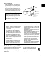
EXAMPLE OF ANTENNA GROUNDING
MAST
ANTENNA
LEAD IN
WIRE
GROUND
CLAMP
ANTENNA
DISCHARGE UNIT
(NEC SECTION 810–20)
ELECTRIC
SERVICE
EQUIPMENT
GROUNDING CONDUCTORS
(NEC SECTION 810–21)
GROUND CLAMPS
POWER SERVICE GROUNDING
ELECTRODE SYSTEM
(NEC ART 250. PART H)
NEC – NATIONAL ELECTRICAL CODE
FCC INFORMATION (for US customers only)
1. IMPORTANT NOTICE : DO NOT MODIFY THIS UNIT!
This product, when installed as indicated in the
instructions contained in this manual, meets FCC
requirements. Modifications not expressly approved by
Yamaha may void your authority, granted by the FCC,
to use the product.
2. IMPORTANT : When connecting this product to
accessories and/or another product use only high
quality shielded cables. Cable/s supplied with this
product MUST be used. Follow all installation instructions. Failure to follow instructions could void your FCC
authorization to use this product in the USA.
3. NOTE : This product has been tested and found to
comply with the requirements listed in FCC Regulations, Part 15 for Class “B” digital devices. Compliance
with these requirements provides a reasonable level of
assurance that your use of this product in a residential
environment will not result in harmful interference with
other electronic devices.
This equipment generates/uses radio frequencies and,
if not installed and used according to the instructions
found in the users manual, may cause interference
harmful to the operation of other electronic devices.
Compliance with FCC regulations does not guarantee
that interference will not occur in all installations. If this
product is found to be the source of interference, which
can be determined by turning the unit “OFF” and “ON”,
please try to eliminate the problem by using one of the
following measures:
Relocate either this product or the device that is being
affected by the interference.
Utilize power outlets that are on different branch (circuit
breaker or fuse) circuits or install AC line filter/s.
In the case of radio or TV interference, relocate/reorient
the antenna. If the antenna lead-in is 300 ohm ribbon
lead, change the lead-in to coaxial type cable.
If these corrective measures do not produce satisfactory results, please contact the local retailer authorized
to distribute this type of product. If you can not locate
the appropriate retailer, please contact Yamaha
Electronics Corp., U.S.A. 6660 Orangethorpe Ave,
Buena Park, CA 90620.
The above statements apply ONLY to those products
distributed by Yamaha Corporation of America or its
subsidiaries.
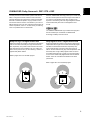
We Want You Listening For A Lifetime
YAMAHA and the Electronic Industries Association’s Consumer
Electronics Group want you to get the most out of your
equipment by playing it at a safe level. One that lets the sound
come through loud and clear without annoying blaring or
distortion – and, most importantly, without affecting your
sensitive hearing.
Since hearing damage from loud sounds is often
undetectable until it is too late, YAMAHA and the
Electronic Industries Association’s Consumer
Electronics Group recommend you to avoid
prolonged exposure from excessive volume levels.
3
01RX-V595a-e/f1
3
6/24/99, 11:42 AM
SUPPLIED ACCESSORIES
ACCESSOIRES FOURNIS
• After unpacking, check that the following parts are included.
• Après le déballage, vérifier que les pièces suivantes sont incluses.
• Remote control
Before using the remote control, install the supplied
batteries. See page 48 for battery installation.
• Télécommande
Avant d’utiliser la télécommande, mettre les piles fournies en
place. Pour la mise en place des piles, voir page 98.
• Indoor FM Antenna
• Antenne FM intérieure
• AM Loop Antenna
• Cadre-antenne AM
• Antenna adapter
(U.S.A. and Canada models only)
• Adaptateur d’antenne
(Modèles pour les États-Unis et le
Canada seulement)
• Batteries (size AA, R6, UM-3)
• Piles (taille AA, R6, UM-3)
4
01RX-V595a-e/f1
4
6/24/99, 11:42 AM
English
FEATURES
● CINEMA DSP: Theater-like Sound
Experience by the Combination of
YAMAHA DSP Technology and Dolby
Digital, Dolby Pro Logic or DTS
● Automatic Input Balance Control for
Dolby Pro Logic decoding
5-Channel Power Amplification
Mininum RMS Output
(0.04% THD, 20 Hz – 20 kHz)
U.S.A. and Canada models
Main: 70 W + 70 W (8 Ω)
Center: 70 W (8 Ω)
Rear: 70 W + 70 W (8 Ω)
● Test Tone Generator for Easier Speaker
Balance Adjustment
● Speaker Output Mode Selection
Australia and China models
Main: 65 W + 65 W (8 Ω)
Center: 65 W (8 Ω)
Rear: 65 W + 65 W (8 Ω)
Sophisticated FM/AM Tuner
Multi-mode Digital Sound Field Processing
●
●
●
●
Digital Sound Field Processor (DSP)
Dolby Digital Decoder
Dolby Pro Logic Decoder
DTS Decoder
● 40-Station Random Access Preset Tuning
● Automatic Preset Tuning
● Preset Station Shifting Capability
(Preset Editing)
● 6-Channel External Decoder Input for
Other Future Formats
● Video Signal Input/Output Capability
(Including S Video Connections)
● SLEEP Timer
● Universal Remote Control with Preset
Manufacturer Codes
CONTENTS
SUPPLIED ACCESSORIES ........................................... 4
FEATURES .................................................................... 5
CAUTION ....................................................................... 6
● Information about DSP
SOUND FIELD PROGRAM ......................................... 36
● Advanced Information
● Introduction
ADJUSTMENTS IN THE “SET MENU” MODE ............ 41
FEATURES OF THE SOUND EFFECTS ....................... 7
CONTROLS AND THEIR FUNCTIONS ....................... 10
● Remote control
● Preparation
REMOTE CONTROL ................................................... 43
SETUP CODES ........................................................... 49
SPEAKER SETUP ....................................................... 13
CONNECTIONS ........................................................... 14
ADJUSTMENTS BEFORE USING THIS UNIT ............ 21
TROUBLESHOOTING ................................................. 50
SPECIFICATIONS ....................................................... 53
● Basic Operation
BASIC OPERATION .................................................... 26
TUNING ....................................................................... 30
SETTING THE SLEEP TIMER ..................................... 35
LIST OF MANUFACTURERS’ CODES ...................... 105
5
01RX-V595a-e/f1
5
6/24/99, 11:42 AM
CAUTION: READ THIS BEFORE OPERATING YOUR UNIT.
1.
To assure the finest performance, please read this manual
carefully. Keep it in a safe place for future reference.
2.
Install this unit in a cool, dry, clean place – away from
windows, heat sources, sources of excessive vibration,
dust, moisture and cold. Avoid sources of humming
(transformers, motors). To prevent fire or electrical shock,
do not expose the unit to rain or water.
3.
Never open the cabinet. If something drops into the set,
contact your dealer.
4.
Do not use force on switches, controls or connection wires.
When moving the unit, first disconnect the power plug and
the wires connected to other equipment. Never pull the
wires themselves.
5.
The openings on the cover assure proper ventilation of the
unit. If these openings are obstructed, the temperature
inside the unit will rise rapidly. Therefore, avoid placing
objects against these openings, and install the unit in a
well-ventilated area to prevent fire and damage.
<China model only>
Be sure to allow a space of at least 20 cm behind, 20 cm
on both sides and 30 cm above the top panel of the unit to
prevent fire and damage.
6.
The voltage used must be the same as that specified on
this unit. Using this unit with a higher voltage than
specified is dangerous and may result in fire or other
accidents. YAMAHA will not be held responsible for any
damage resulting from the use of this unit with a voltage
other than that specified.
7.
Digital signals generated by this unit may interfere with
other equipment such as tuners, receivers and TVs. Move
this unit farther away from such equipment if interference is
observed.
8.
Always set the VOLUME control to “ ” before starting the
audio source play. Increase the volume gradually to an
appropriate level after playback has been started.
9.
Do not attempt to clean the unit with chemical solvents; this
might damage the finish. Use a clean, dry cloth.
10. Be sure to read the “TROUBLESHOOTING” section
regarding common operating errors before concluding that
the unit is faulty.
This unit is not disconnected from the AC power source as
long as it is connected to the wall outlet, even if this unit
itself is turned off. This state is called the standby mode. In
this state, this unit is designed to consume a very small
quantity of power.
FREQUENCY STEP switch
(China model only)
Because the interstation frequency spacing differs in
different areas, set the FREQUENCY STEP switch (located
at the rear) according to the frequency spacing in your area.
Before setting this switch, disconnect the AC power plug of
this unit from the AC outlet.
IMPORTANT
Please record the serial number of this unit in the space
below.
MODEL:
Serial No.:
The serial number is located on the rear of the unit.
Retain this Owner’s Manual in a safe place for future
reference.
WARNING
TO REDUCE THE RISK OF FIRE OR ELECTRIC SHOCK,
DO NOT EXPOSE THIS UNIT TO RAIN OR MOISTURE.
FOR CANADIAN CUSTOMERS
To prevent electric shock, match wide blade of plug to wide
slot and fully insert.
This Class B digital apparatus complies with Canadian
ICES-003.
11. When not planning to use this unit for a long period of time
(e.g., a vacation), disconnect the AC power plug from the
wall outlet.
12. To prevent lightning damage, disconnect the AC power
plug and disconnect the antenna cable when there is an
electrical storm.
13. Grounding or polarization – Precautions should be taken so
that the grounding or polarization of the unit is not
defeated.
14. AC outlet
Do not connect audio equipment to the AC outlet on the
rear panel if that equipment requires more power than the
outlet is rated to provide.
15. Voltage Selector (China model only)
The voltage selector on the rear panel of this unit must
be set for your local main voltage BEFORE plugging
into the AC main supply.
Voltages are 110/120/220/240 V AC, 50/60 Hz.
6
01RX-V595a-e/f1
6
6/24/99, 11:42 AM
English
FEATURES OF THE SOUND EFFECTS
Introduction
Welcome to the exciting world of digital home entertainment.
This unit is one of the most complete and advanced AV
receivers available. Some of the more advanced features may
not be familiar to you, but they are easy to use. State-of-the-art
technologies such as Dolby Digital and Digital Theater Systems
(DTS) may be new to your home, but you have probably
experienced the amazing realism they bring to feature films in
theaters around the world.
To make the listening experience even more enjoyable, this unit
includes a number of exclusive, digitally created listening
environments known as digital sound fields. Choosing a sound
field program is like transporting yourself to such venues as an
outdoor arena, a European church, or a cozy jazz club. Take
some time now to read more about these features and enjoy
the new experiences this unit brings to your home theater.
Digital Sound Field Processing
What is it that makes live music so good? Today’s advanced
sound reproduction technology lets you get extremely close to
the sound of a live performance, but the chances are that you’ll
still notice something missing — the acoustic environment of
the live concert hall. Extensive research into the exact nature
of the sonic reflections that create the ambience of a large hall
has made it possible for YAMAHA engineers to bring you this
same sound to your listening room, so you’ll feel all the sound
of a live concert.
Furthermore, our technicians, armed with sophisticated
measuring equipment, have even made it possible to capture
the acoustics of a variety of actual concert halls, theaters, etc.
from around the world, to allow you to accurately re-create any
one of these live performance environments, all in your own
home.
Dolby Pro Logic
Dolby Surround has been used in movie theaters since the midseventies. It has also been available in home entertainment
systems since the late eighties and continues to be a popular
format for home theater systems. It uses four discrete channels
and five speakers to reproduce realistic and dynamic sound
effects: two main channels (left and right), a center channel for
dialog, and a rear channel for special sound effects. The rear
channel reproduces sound within a narrow frequency range.
Most video tapes and laser discs include Dolby Surround
encoding, as do many TV and cable broadcasts. The Dolby Pro
Logic decoder built into this unit employs a digital signal
processing system that stabilizes each channel for even more
accurate sound positioning than is available with standard
analog processors.
7
01RX-V595a-e/f1
7
6/24/99, 11:42 AM
Dolby Digital
Dolby Digital is the next level of the Dolby Surround sound
system that was developed for 35 mm-film movies by
employing low bit-rate audio coding.
Dolby Digital is a digital surround sound system that provides
completely independent multi-channel audio to you. Dolby
Digital provides five full-range channels in what is sometimes
referred to as a “3/2” configuration: three front channels (left,
center and right), and two surround channels. A sixth bass-only
effect channel is also provided for output of LFE (low frequency
effect), or low bass effects that are independent of other
channels. (This is called the “LFE channel”.) This channel is
counted as 0.1, thus giving rise to the term 5.1 channels in
total.
Compared to Dolby Surround, which is referred to a “3/1”
system (left front, center, right front and just one surround
channel), Dolby Digital features two surround channels, called
stereo or split surrounds, each offering the same full-range
fidelity as the three front channels.
By using the built-in Dolby Digital decoder, you can experience
the dramatic realism and impact of Dolby Digital theater sound
in your home.
The wide dynamic range of sound reproduced by the five fullrange channels and precise sound orientation by digital sound
processing provides listeners with excitement and realism that
have never been experienced before.
Dolby Digital forms 5.1 channels as already mentioned, but it
can also form fewer channels, for example 2-channel stereo
and monaural. You may be able to find some 2-channel stereo
and/or monaural sources encoded with Dolby Digital in the
market.
Laser disc and DVD are home audio/video program sources
that could benefit from Dolby Digital. In the near future, Dolby
Digital will also be applied to DBS, CATV and HDTV. The
ongoing release of Dolby Digital theatrical films now underway
will provide an immediate source of Dolby Digital encoded
video software.
Manufactured under license from Dolby Laboratories. “Dolby”,
“Pro Logic” and the double-D symbol are trademarks of Dolby
Laboratories.
DTS Digital Surround
DTS (Digital Theater Systems) was developed to replace
analog soundtracks of movies with six discrete channels of
digital soundtracks, and it is now installed in many theaters
around the world. The DTS digital playback system changed
the way we experienced movies in theaters with six discrete
channels of superb digital audio.
DTS technology, through intense research and development
has made it possible to deliver similar encode/decode discrete
technology to home audio surround-sound entertainment.
DTS Digital Surround is an encode/decode system which
delivers six channels of master-quality, 20-bit audio; technically,
it is 5.1 channels, which means 5 full-range (left, center, right
and two surround) channels, plus a subwoofer (LFE) channel
(as “0.1”). It is compatible with the 5.1 speaker configurations
that are currently available for home theater systems.
Laser disc, compact disc and DVD are home audio formats by
which DTS can present its high-quality multi-channel audio. (In
addition to movies on laser discs, many exciting new multichannel music recordings will also become available in the
form of DTS-encoded compact discs.)
Manufactured under license from Digital Theater Systems, Inc.
US Pat. No. 5,451,942 and other world-wide patents issued
and pending. “DTS”, “DTS Digital Surround”, are trademarks of
Digital Theater Systems, Inc. Copyright 1996 Digital Theater
Systems, Inc. All Rights Reserved.
The DTS Digital Surround algorithm is designed to encode the
six channels of 20-bit audio on to some laser discs, compact
discs and DVDs with considerably less data compression.
By using the DTS decoder built into this unit, you can
experience the dramatic realism and impact of the DTSinstalled theater’s high quality sound in your home.
8
01RX-V595a-e/f1
8
6/24/99, 11:42 AM
English
CINEMA DSP: Dolby Surround + DSP / DTS + DSP
The Dolby Surround sound and DTS systems show their full
ability in a large movie theater, because movie sounds are
originally designed to be reproduced in a large movie theater
that uses a multitude of speakers. Trying to create a sound
environment similar to that of a movie theater in your home is
difficult because of the room size, material inside the walls, the
number of speakers, and so on. In other words, your listening
room is very different from a movie theater.
However, YAMAHA DSP technology allows you to create nearly
the same sound experience as that of a large movie theater in
your home by compensating for the lack of presence and
dynamics in the listening room with original digital sound fields
combined with Dolby Surround or DTS Digital Surround
sounds.
CINEMA DSP
The YAMAHA “CINEMA DSP” logo indicates those programs
that are created by the combination of YAMAHA DSP
technology and Dolby Surround or DTS.
Dolby Pro Logic + 2 Digital Sound Fields
Dolby Digital or DTS + 3 Digital Sound Fields
Digital sound fields are created on the presence side and the
rear surround side of the Dolby Pro Logic-decoded sound
field, respectively. They create a wide acoustic environment
and emphasize the surround effect in the room, letting you
feel as much presence as if you were watching a movie in a
popular Dolby Stereo theater.
Digital sound fields are created on the presence side and the
independent left and right surround sides of the Dolby Digitaldecoded or DTS-decoded sound field, respectively. They
create a wide acoustic environment and strong surround
effect in the room without losing high-channel separation. With
the wide dynamic range of Dolby Digital or DTS sound, this
sound field combination lets you feel as if you were watching
a movie in the newest Dolby Digital theater or DTS-installed
theater. This is the most ideal home theater sound at the
present time.
Refer to pages 36 to 37 for the DSP program.
Refer to pages 36 to 37 for the DSP program.
9
01RX-V595a-e/f1
9
6/24/99, 11:42 AM
CONTROLS AND THEIR FUNCTIONS
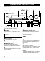
FRONT PANEL
INPUT
VCR • V–AUX • TV/DBS • DVD/LD • CD • TUNER • PHONO
VOLUME
18
12
20
STANDBY/ON
22
8
80
2
40
TAPE/MD MON
/EXT. DECODER
4
0
–dB
A/ B/ C/ D/ E
1
2
3
5
4
6
7
8
MEMORY
MAN’L/AUTO FM
BASS
PHONES
TREBLE
1
1
1
2
2
ON
OFF
4
4
5
5
2
2
3
3
4
4
5
FM/AM
5
DOWN
TUNING
UP
INPUT MODE
AUTO/MAN’L MONO
TIME/
LEVEL
0
1
1
2
3
3
TUNING
MODE
BALANCE
0
0
SPEAKERS
A
B
EDIT
1
SET
MENU
VIDEO AUX
EFFECT
2
3
3
PROGRAM
4
4
L 5
5 R
8 VIDEO
VIDEO
L
AUDIO
R
Refer to pages 43 to 48 for the remote control.
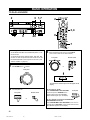
1 STANDBY/ON
6 TUNING MODE (AUTO/MAN’L MONO)
Press this switch to turn on the power of this unit. Press it
again to set this unit in the standby mode.
Press this button to switch the tuning mode to automatic or
manual. To select the automatic tuning mode, press this button
so that the “AUTO TUNING” indicator lights up on the display.
To select the manual tuning mode, press this button so that the
“AUTO TUNING” indicator goes off.
Standby mode
In this state, this unit consumes a very small quantity of
power to receive infrared-signals from the remote control.
2 Remote control sensor
7 FM/AM
Press this button to switch the reception band between FM and
AM.
This receives signals from the remote control.
8 TUNING UP/DOWN
3 Display
This button is used for tuning. Press the UP side to tune in to
higher frequencies, and press the DOWN side to tune in to
lower frequencies.
This shows various information. (Refer to page 12 for details.)
4 MEMORY (MAN’L/AUTO FM)
Press this button to store the broadcasting stations.
When this button is pressed and held for more than three
seconds, automatic preset tuning begins.
5 EDIT
This button is used to exchange the assigment of two preset
stations with each other.
9 TAPE/MD MON / EXT. DECODER
Press this button to play a tape or an MD. The “TAPE/MD
MON” indicator lights up on the display.
When you press the button next, the “TAPE/MD MON” indicator
goes off, “EXT. DECDR” appears on the display and you can
play the signal connected to the EXTERNAL DECODER
INPUT terminals.
0 INPUT
Turn this selector to select the input source (VCR, VIDEO AUX,
TV/DBS, DVD/LD, CD, TUNER, PHONO) that you want to
listen to or watch.
The name of the selected input source appears on the display.
10
01RX-V595a-e/f1
10
6/24/99, 11:42 AM
i BALANCE
This button switches between the DVD/LD and TV/DBS input
signal modes.
This control is used to raise or lower the volume level.
This control is only effective for the sound from the main
speakers.
Turn the control to adjust the balance of the output volume to
the left and right speakers to compensate for sound imbalance
caused by the speaker location or listening room conditions.
e PHONES jack
o TIME/LEVEL
When you use headphones, connect the headphones to the
PHONES jack. You can listen to the sound to be output from
the main speakers through the headphones.
When using headphones only, set both SPEAKERS A and B to
the OFF position and switch off the digital sound field processor
(so that no DSP program name appears on the display) by
pressing EFFECT.
Press this button to select the item in the TIME/LEVEL mode.
w VOLUME
p +/–
These buttons are used to adjust the settings of the SET MENU
mode and the TIME/LEVEL mode. In the TIME/LEVEL mode,
press + to increase the delay time or speaker output level.
Press – to decrease the delay time or speaker output level.
r SPEAKERS
a SET MENU
Set A or B (or both A and B) to the ON position for the main
speaker system (connected to this unit) that you want to use.
Set the button(s) for the main speaker system you don’t want to
use to the OFF position.
Press this button to select functions in the SET MENU mode.
t A/B/C/D/E
Press this button to select one of a group (A to E) of preset
stations.
y Preset station number selector
Each of these buttons selects a preset station number (1 to 8).
u Tone controls
These controls are only effective for the sound from the main
speakers.
BASS
Use this control to increase or decrease the low-frequency
response. The “0” position produces a flat response.
TREBLE
Use this control to increase or decrease the high-frequency
response. The “0” position produces a flat response.
s PROGRAM selector
Press or to select a DSP program.
The name of the selected program appears on the display.
d EFFECT
Press this button once to switch the effect speakers (center and
rear) on or off. If you turn off the effect by using EFFECT, all
Dolby Digital and DTS audio signals are directed to the main
left and right channels. In that case, the left and right channel
signal levels may not match.
f VIDEO AUX terminals
Connect an auxiliary video or audio input source such as a
camcorder to these terminals. If the connected video unit has
an S video output terminal, connect it to the S VIDEO terminal
to obtain a high-resolution picture. The source connected to
these terminals can be selected by INPUT.
11
01RX-V595a-e/f1
11
6/24/99, 11:42 AM
English
q INPUT MODE
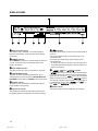
DISPLAY PANEL
1 Multi-information display
This displays various information, for example the station
frequency, preset station number and name of the selected
input source.
2 MEMORY indicator
When MEMORY is pressed, this indicator flashes for about five
seconds. During this period, the displayed station can be
stored in the memory.
3 AUTO TUNING indicator
This lights up when the unit is in the automatic tuning mode.
4 TAPE/MD MON indicator
This lights up when the tape deck (or MD recorder, etc.) is
selected as the input source by pressing TAPE/MD MON / EXT.
DECODER on the front panel or TAPE/MD on the remote control.
5 STEREO indicator
This lights up when an FM stereo broadcast with sufficient
signal strength is being received.
6 Signal-level indicator
7
indicators
Either “dts” indicator lights up when the built-in DTS decoder is
turned on.
The red “dts” indicator lights up when playing a CD or LD
encoded with DTS.
The orange “dts” indicator lights up when playing a DVD
encoded with DTS.
* An orange “dts” indicator may light up when playing a CD or
LD encoded with DTS after playing a video-CD or DVD on a
DVD/LD combi-player.
8
,
and
indicators
” lights up when the built-in Dolby Digital decoder is
“
on and the signals of the selected source encoded with Dolby
Digital are not in 2-channel. “
” lights up when the built-in
digital sound field processor is on, and “
” lights up
when the built-in Dolby Pro Logic decoder is on. Depending on
the selected DSP program, both “
” and “
”, or
” and “
” will light up.
both “
9 SLEEP indicator
This lights up while the built-in SLEEP timer is functioning.
This indicates the signal level of the station being received.
If multipath interference is detected, the indication decreases.
12
01RX-V595a-e/f1
12
6/24/99, 11:42 AM
English
SPEAKER SETUP
SPEAKERS TO BE USED
This unit is designed to provide the best sound-field quality with
a 5-speaker configuration, using main speakers, rear speakers
and a center speaker.
The main speakers are used for the main source sound plus
the effect sounds. They will probably be the speakers from
your present stereo system. The rear speakers are used for
the effect and surround sounds, and the center speaker is for
the center sounds (dialog, vocals, etc.). If for some reason it is
not practical to use a center speaker, you can do without it.
Best results, however, are obtained with the full system.
Use of a subwoofer expands your sound field
It is also possible to further expand your system with the
addition of a subwoofer. The use of a subwoofer is effective
not only for reinforcing bass frequencies from any or all
channels, but also for reproducing the LFE (low frequency
effect) sound with high fidelity when playing back a source that
is Dolby Digital or DTS-decoded. The YAMAHA Active Servo
Processing Subwoofer System is ideal for natural and lively
bass reproduction.
The main speakers should be high-performance models and
have enough power-handling capacity to accept the maximum
output of your audio system.
The other speakers do not have to be equal to the main
speakers. For precise sound localization, however, it is ideal to
use high-performance models that can reproduce sounds over
the full range for the center speaker and the rear speakers.
SPEAKER PLACEMENT
Refer to the following diagram when you place the speakers.
Main:
The position of your present stereo speaker
system.
Rear:
Behind your listening position, facing slightly
inward. Nearly 1.8 m (approx. 6 feet) up from the
floor.
Center:
Precisely between the main speakers. (To avoid
interference with TV sets, use a magnetically
shielded speaker.)
Main
speaker (R)
Subwoofer
Center speaker
Main
speaker (L)
Rear
speaker (R)
Subwoofer: The position of the subwoofer is not as critical,
because low bass tones are not highly directional.
Rear
speaker
(L)
Note: If the center speaker (principally, it reproduces dialog, vocals, etc.) is not used, the sound will be output from the left and
right main speakers. In that case, be sure to select the NONE position for “CNTR” in the SET MENU mode. (See page 21
for details.)
13
01RX-V595a-e/f2
13
6/24/99, 11:42 AM
CONNECTIONS
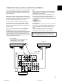
Never plug in this unit and other components until all connections have been completed.
CONNECTIONS WITH OTHER COMPONENTS
Use RCA-type pin plug cables for connecting audio/video components with the exception described later.
When making connections between this unit and other components, be sure all connections are made correctly, that is to say L
(left) to L, R (right) to R, “+” to “+” and “–” to “–”. Also, refer to the owner’s manual for each component to be connected to this unit.
* If you have YAMAHA components numbered as !, #, $, etc. on the rear panel, connections can be made easily by making sure
to connect the output (or input) terminals of each component to the same-numbered terminals of this unit.
AC OUTLET(S) (SWITCHED)
U.S.A., Canada and China models ....................... 2 OUTLETS
Australia model ......................................................... 1 OUTLET
Turntable
DVD player,
LD player, etc.
Monitor TV
Use these to connect the power cords from your components to
this unit.
The power to the AC OUTLET(S) is controlled by this unit’s
STANDBY/ON or the provided remote control’s POWER and
STANDBY. These outlets will supply power to any connected
component whenever this unit is turned on.
The maximum power (total power consumption of components)
that can be connected to the AC OUTLET(S) is 100 watts.
(U.S.A. model)
To AC outlet
CD player
Tape deck,
MD recorder, etc.
TV/DBS tuner
VCR
(Video cassette recorder)
GND terminal (for turntable use)
Connecting the ground (earth) wire of the turntable to the GND terminal will normally minimize hum, but in some cases, better
.
results may be obtained with the ground wire disconnected.
14
01RX-V595a-e/f2
14
6/24/99, 11:42 AM
English
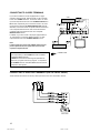
CONNECTING TO DIGITAL (COAXIAL AND/OR OPTICAL) TERMINALS
If your DVD (LD) player, TV/DBS tuner, etc. are equipped with
coaxial or optical digital audio signal output terminals, they can
be connected to this unit’s COAXIAL and/or OPTICAL digital
signal input terminals.
Digital audio signals are transmitted with less loss than analog
audio signals. In addition, digital audio signal connections are
necessary, especially for an LD player or a DVD player, to send
signals encoded with Dolby Digital or DTS to this unit.
To make a connection between optical digital audio signal
terminals, remove the cover from each terminal, and then
connect them by using a commercially available optical fiber
cable that conforms to EIAJ standards. Other cables might not
function correctly.
Even if you connect an audio/video unit to the COAXIAL (or
OPTICAL) terminal of this unit, you must keep the unit
connected with the same-named analog audio signal terminals
of this unit, because a digital signal cannot be recorded by a
tape deck, MD recorder or VCR connected to this unit. You can
easily switch the selection of input signals between “digital” and
“analog.” (See page 28 for details.)
Notes
• When connecting an audio/video unit to both the digital and
analog terminals of this unit, make sure to connect between
both terminals of the same name.
• Be sure to attach the covers when the OPTICAL terminals
are not being used in order to protect them from dust.
• The input signal from the DVD/LD input terminals is selected
in the following order of priority with the input mode set to the
AUTO position:
1 COAXIAL terminal
2 OPTICAL terminal
3 Analog terminal
• If the DIGITAL OUT data of the player has been processed in
any way, you may not be able to perform DTS playback even
if you make a digital connection between this unit and the
player.
• All digital audio signal input terminals are applicable to
sampling frequencies of 32 kHz, 44.1 kHz and 48 kHz.
No sound will be generated when connecting your LD
player’s Dolby Digital RF signal output terminal directly to
this unit’s COAXIAL DVD/LD digital signal input terminal.
DVD or LD player*
* If your LD player has a Dolby Digital RF signal
output terminal, be sure to use the RF
demodulator (separately purchased).
TV/DBS tuner
(U.S.A. model)
15
01RX-V595a-e/f2
15
6/24/99, 11:42 AM
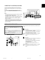
CONNECTING TO S VIDEO TERMINALS
If you have a VCR and a monitor equipped with “S” (highresolution) video terminals, those terminals can be connected
to this unit’s S VIDEO terminals. Connect the VCR’s “S” video
input and output terminals to this unit’s S VIDEO VCR OUT and
IN terminals, respectively, and connect the monitor’s “S” video
input terminal to this unit’s S VIDEO MONITOR OUT terminal.
Otherwise, connect the VCR’s composite video terminals to this
unit’s composite video terminals, and connect the monitor’s
composite video input terminal to this unit’s composite
MONITOR OUT terminal.
In addition, if you have a DVD or LD player equipped with an
“S” video terminal, connect the DVD/LD player’s “S” video
output terminal to this unit’s S VIDEO DVD/LD terminal.
VCR
S
Note
If video signals are sent to both S VIDEO input and composite input terminals, the signals will be sent to their
respective output terminals.
DVD/LD player
S
S VIDEO terminals
This unit provides you with S VIDEO terminals in addition
to standard VIDEO terminals.
S VIDEO terminals transmit video signals separated into
luminance (Y) signals and color (C) signals. In comparison
with S VIDEO terminals, standard VIDEO terminals transmit
“composite” video signals.
S VIDEO cable
CONNECTING TO VIDEO AUX TERMINALS (ON THE FRONT PANEL)
These terminals are used to connect any video input source such as a camcorder to this unit.
S
S
Camcorder
16
01RX-V595a-e/f2
16
S
S
S
6/24/99, 11:42 AM
Monitor TV
English
CONNECTING TO AN EXTERNAL DECODER
This unit is equipped with additional 6-channel audio signal
input terminals for inputting signals from an external decoder to
this unit.
Connect the 6-channel audio signal output terminals of the
decoder to the EXTERNAL DECODER INPUT terminals of this
unit.
Notes
• When signals input to these terminals are selected, the digital
sound field processor cannot be used.
• The settings of “CNTR”, “REAR”, “MAIN” and “BASS” in the
SET MENU mode have no effect on the signals input to these
terminals. The setting of “M.LVL” is effective. (Refer to
page 21 for details.)
• Adjustment of the output level of the center speakers, rear
speakers and subwoofer is effective when the signals input to
these terminals are selected as the input source. (Refer to
page 39 for details.)
External decoder with
6-channel discrete
outputs
(U.S.A. model)
IMPEDANCE SELECTOR SWITCH
WARNING
Do not change the IMPEDANCE SELECTOR switch setting
while the power to this unit is on, otherwise this unit may be
damaged.
If this unit fails to turn on when the STANDBY/ON switch is
pressed, the IMPEDANCE SELECTOR switch may not be
fully set to either end. If so, set the switch to either end fully
when this unit is in the standby mode.
IMPEDANCE SELECTOR
Select the position whose requirements your speaker system
meets.
(Upper position)
Main: If you use one pair of main speakers, the impedance of
each speaker must be 4 Ω or higher.
If you use two pairs of main speakers, the impedance
of each speaker must be 8 Ω or higher.
Center: The impedance of the speaker must be 6 Ω or higher.
Rear: The impedance of each speaker must be 6 Ω or
higher.
(U.S.A. model)
(Lower position)
Main: If you use one pair of main speakers, the impedance of
each speaker must be 8 Ω or higher.
If you use two pairs of main speakers, the impedance
of each speaker must be 16 Ω or higher.
<Canada model only>
The impedance of each speaker must be 8 Ω or
higher.
Center: The impedance of the speaker must be 8 Ω or higher.
Rear: The impedance of each speaker must be 8 Ω or
higher.
17
01RX-V595a-e/f2
17
6/24/99, 11:43 AM
CONNECTING SPEAKERS
Main speakers A
Right
Main speakers B
Left
Right
Left
(U.S.A. model)
Rear speakers
Left
Center speaker
Subwoofer system
Note
Use speakers with the specified impedance shown on the
rear panel of this unit.
Main speaker connections
One or two speaker systems can be connected to this unit. If
you use only one speaker system, connect it to either of the
SPEAKERS A or B terminals.
Subwoofer connection
You may wish to add a subwoofer to reinforce low frequencies
or to output low bass sound from the subwoofer channel.
If you have a subwoofer with built-in amplifier, including the
YAMAHA Active Servo Processing Subwoofer System, connect
the SUBWOOFER OUTPUT terminal of this unit to the input
terminal of the subwoofer system.
Rear speaker connections
A rear speaker system can be connected to this unit. Place
them to the rear of your listening position.
Center speaker connection
A center speaker can be connected to this unit. Place it on or
under the TV.
18
01RX-V595a-e/f2
Right
18
6/24/99, 11:43 AM
English
How to connect
Connect the SPEAKERS terminals to your speakers with wire of the proper gauge, cut as short as possible. If the connections are
faulty, no sound will be heard from the speakers. Make sure that the polarity of the speaker wires is correct, that is the + and –
markings are observed. If these wires are reversed, the sound will be unnatural and lack bass.
Caution
Do not let the bare speaker wires touch each other and do not let them touch any metal part of this unit. This could
damage the unit and/or speakers.
Connecting to the MAIN SPEAKERS terminals
Connecting to the REAR and CENTER
SPEAKERS terminals
Red: positive (+)
Black: negative (–)
Red: positive (+)
Black: negative (–)
1 Unscrew the knob.
2 Remove approx. 5 mm
(1/4”) of insulation from
each of the speaker
wires and insert one
bare wire into each
terminal.
3 Tighten the knob to
secure the wire.
2
1
3
1
3
2
1 Press the tab.
2 Remove approx. 5 mm
(1/4”) of insulation from
each of the speaker
wires and insert one
bare wire into each
terminal.
3 Release the tab to
secure the wire.
Banana plug connections are also possible. Simply insert the
banana plug connector into the corresponding terminal.
19
01RX-V595a-e/f2
19
6/24/99, 11:43 AM
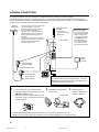
ANTENNA CONNECTIONS
Each antenna should be correctly connected to the designated terminals, referring to the following diagram.
Both AM and FM indoor antennas are included with this unit. In general, these antennas will probably provide sufficient signal
strength. Nevertheless, a properly installed outdoor antenna will give clearer reception than an indoor one. If you experience poor
reception quality, an outdoor antenna may result in improvement.
Outdoor
FM antenna
* You may be unable to obtain good FM radio
reception depending on your local
conditions (distance from the broadcast
station, interposing buildings and
mountains, etc.). Consult your dealer or
authorized service center and be sure to
install an antenna that suits your local
conditions.
Install the special FM outdoor antenna in a
high place as far away from any roads as
possible to avoid being affected by
automobile ignition noise.
Indoor FM antenna
(included)
Outdoor AM antenna
* Firmly insert the
connector into the FM
ANT terminal.
* If you cannot obtain good
reception with the AM loop
antenna, connect 5 m to
10 m of vinyl covered wire
to the AM ANT terminal
and extend it outdoors
from a window. (Be sure
to also connect the AM
loop antenna at this time.)
(U.S.A. model)
AM loop
antenna
(included)
75-ohm/300-ohm
antenna adapter
75-ohm coaxial cable
75-ohm/300-ohm
antenna adapter
Ground
300-ohm feeder
GND terminal
For maximum safety and minimum interference, connect the
GND terminal to a good earth ground. A good earth ground
is a metal stake driven into moist earth.
Connecting the AM loop antenna
1
1 Press the tab and unlock the terminal hole.
2 Connect the AM loop antenna lead wires to the
AM ANT and GND terminals.
3 Return the tab to its original position to lock the
lead wires. Lightly pull the lead wires to confirm
a good connection.
2
Attach the loop antenna to the
antenna stand.
3
Orient the AM loop
antenna so that the best
reception is obtained.
Loop antenna
1
3
2
Antenna stand
• The AM loop antenna should be placed away from this unit. The antenna may be hung on a wall.
• The AM loop antenna should always be connected, even if an outdoor AM antenna is connected to this unit.
20
01RX-V595a-e/f2
20
6/24/99, 11:43 AM
English
ADJUSTMENTS BEFORE USING THIS UNIT
SELECTING THE OUTPUT MODES
This unit provides you with the following five functions to determine the method of distributing output signals to speakers suitable for
your audio system. When speaker connections have all been completed, select the proper setting for each function to make the
best use of your speaker system. (See “ADJUSTMENTS IN THE ‘SET MENU’ MODE” on page 41.)
1. CNTR (CENTER SPEAKER) 2. REAR (REAR SPEAKERS)
4. BASS (LFE/BASS OUT)
5. M.LVL (MAIN LEVEL)
DESCRIPTION OF EACH FUNCTION
CNTR (CENTER SPEAKER)
Choices: LARGE/SMALL/NONE
Preset position: LARGE
LARGE: Select this position when your center speaker is
approximately the same size as the main speakers.
SMALL: Select this position when you use a center speaker
that is smaller than the main speakers.
In this position, low bass signals (below 90 Hz) on the
center channel are output from the main speakers (or
the SUBWOOFER OUTPUT terminal if the SMALL
position is selected for “MAIN” and the SW position is
selected for “BASS”).
NONE: Select this position when you do not have a center
speaker (four speaker system). The center channel
sound will be output from the left and right main
speakers.
REAR (REAR SPEAKERS)
Choices: LARGE/SMALL
Preset position: LARGE
LARGE: Select this position if your rear speakers have high
ability for bass reproduction, or if a subwoofer is
connected in parallel to the rear speaker.
In this position, full-range signals are output from the
rear speakers.
SMALL: Select this position if your rear speakers do not have
high ability for bass reproduction.
In this position, low bass signals (below 90 Hz) on
the rear channels are output from the SUBWOOFER
OUTPUT terminal (or the main speakers if the MAIN
position is selected for “BASS”).
MAIN (MAIN SPEAKERS)
Choices: LARGE/SMALL
Preset position: LARGE
LARGE: Select this position if your main speakers have high
ability for bass reproduction.
In this position, full-range signals present on the
main channels are output from the main speakers.
SMALL: Select this position if your main speakers do not
have high ability for bass reproduction. However, if
your system does not include a subwoofer, do not
select this position.
In this position, low bass signals (below 90 Hz) on
the main channels are output from the
SUBWOOFER OUTPUT terminal if the SW or BOTH
position is selected for “BASS”.
3. MAIN (MAIN SPEAKERS)
BASS (LFE/BASS OUT)
Choices: SW/MAIN/BOTH
Preset position: SW
MAIN:
Select this position if your system does not include a
subwoofer.
In this position, full-range signals present on the
main channels, signals from the LFE channel and
other low bass signals that are distributed from other
channels are output from the main speakers.
SW/BOTH:
Select either the SW or BOTH position if your
system includes a subwoofer.
In either position, signals on the LFE channel and
other low bass signals that are distributed from other
channels are output from the SUBWOOFER
OUTPUT terminal.
When the LARGE position is selected for “MAIN”, in
the SW position, no signal is distributed from the
main channels to the SUBWOOFER OUTPUT
terminal; however, in the BOTH position, low bass
signals from the main channels are output to both
the main speakers and the SUBWOOFER OUTPUT
terminal.
M.LVL (MAIN LEVEL)
Choices: NRML (NORMAL)/–10 dB
Preset position: NRML (NORMAL)
NRML (NORMAL):
Normally select this position.
–10 dB: Select this position if the sound output from the main
speakers is too loud and cannot be balanced with
the sound output from the center and rear speakers.
In this position, the sound output from the main
speakers is attenuated.
Note
The settings of “CNTR”, “REAR”, “MAIN” and “BASS” have no
effect on the signals input to the EXTERNAL DECODER
INPUT terminals on the rear of this unit.
21
01RX-V595a-e/f2
21
6/24/99, 11:43 AM
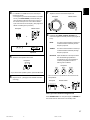
ADJUSTMENT METHOD
Adjustments should be made while watching the information on this unit’s display.
1
2
1
3
2
3
When adjusting with the remote control, set the
SELECTOR DIAL to the AMP/TUN or DSP position on the
remote control.
3
Front panel
or
1
Press + or – once or more to select the setting you
want.
Remote control
Turn the power on.
Front panel
or
Remote control
or
2
Press SET MENU once or more to select the function
“CNTR” on the display.
Front panel
Remote control
4
Repeat steps 2 and 3 to change the settings for
“REAR”, “MAIN”, “BASS” and/or “M.LVL” in the same
way.
or
* After pressing SET MENU once on the remote control, you
can also select the function by pressing . (Pressing
goes back one selection.)
22
01RX-V595a-e/f2
22
6/24/99, 11:43 AM
English
SPEAKER BALANCE ADJUSTMENT
This procedure lets you adjust the sound output level balance between the main, center and rear speakers by using the built-in test
tone generator. When this adjustment is performed, the sound output level heard at the listening position will be the same from
each speaker. This is important for the best performance of the digital sound field processor, the Dolby Digital decoder, the Dolby
Pro Logic decoder and the DTS decoder.
The adjustment of each speaker output level should be done at your listening position with the remote control.
After completing the adjustment of the output level for each speaker, use VOLUME (
) on the remote control at your
listening position to check if the adjustments are satisfactory.
2
1
5,9
2
6
3
8
4 4,7
Set the SELECTOR DIAL to the AMP/TUN or DSP position
on the remote control.
2
Turn the power on.
Front panel
Remote control
or
or
1
Set VOLUME to the “ ” position.
Front panel
3
Select the main speakers to be used.
Front panel
* If you use two main speaker systems, press both A and B.
23
01RX-V595a-e/f2
23
6/24/99, 11:43 AM
4
Set BASS, TREBLE and BALANCE to the “0” position.
6
Front panel
5
Press TEST so that “TEST LEFT” appears on the
display.
Remote control
Turn up the volume.
Remote control
You will hear a test tone (like pink noise) from each
speaker for about two seconds in following order: left main
speaker, center speaker, right main speaker, right rear
speaker and left rear speaker. The display changes as
shown below.
Main (L)
Center
Main (R)
Rear (R)
Rear (L)
* If the function “CNTR” in the SET MENU mode is set to
the NONE position, you will hear the center channel test
tone from the left and right main speakers.
7
Adjust BALANCE so that the sound output level of the
left main speaker and the right main speaker is the
same.
Front panel
24
01RX-V595a-e/f2
24
6/24/99, 11:43 AM
Adjust the sound output levels of the center speaker
and the rear speakers so that they become almost the
same as that of the main speakers.
Press TIME/LEVEL once or more to select the speaker
to be adjusted so that “CENTER”, “R SUR.” or “L SUR.”
appears on the display.
Remote control
* You cannot adjust the delay time while the test tone is
sounding even if “DELAY” appears on the display
after pressing TIME/LEVEL once or more.
Adjust the level.
* Pressing raises and lowers the level.
* While adjusting, the test tone is heard from the
selected speaker.
Remote control
9
When the adjustment is finished, press TEST again to
stop the test tone.
Remote control
25
01RX-V595a-e/f2
25
6/24/99, 11:43 AM
English
8
Notes
• Once you have completed these adjustments, you can only
adjust the overall sound level of your audio system by using
VOLUME (or VOLUME (
) on the remote control).
• If you use external power amplifiers, you may also use their
volume controls to achieve the proper balance.
• If the function “CNTR” in the SET MENU mode is set to the
NONE position, the sound output level of the center speaker
cannot be adjusted in step 8. The center sound is automatically output from the left and right main speakers.
• If there is insufficient sound output from the center and rear
speakers, you may decrease the main speaker output level
by setting “M.LVL” to “–10 dB”.
BASIC OPERATION
TO PLAY A SOURCE
2
3 1,7
2
3,4
5
8
8
48
7
When using the remote control
• Set the SELECTOR DIAL to the AMP/TUN position on the
remote control.
• To operate the CD player, DVD/LD player, tape deck, MD
recorder, or other components with this remote control, set
the SELECTOR DIAL to the component to be used. (See
“SETUP CODES” on page 49.)
1
3
Select the desired input source by using INPUT.
(Turn on the monitor TV for video sources.)
Front panel
Remote control
or
Set VOLUME to the “ ” position.
Front panel
The name of the selected input source will appear on the
display.
2
Turn the power on.
Front panel
Remote control
or
To play a tape or an MD
Press TAPE/MD MON / EXT. DECODER
on the front panel or TAPE/MD on the
remote control so that the “TAPE/MD
MON” indicator lights up on the display.
To use a decoder connected to the EXTERNAL
DECODER INPUT terminals
Press TAPE/MD MON / EXT. DECODER once or more on
the front panel or EXT. DEC. on the remote control so that
“EXT. DECDR” appears on the display.
26
01RX-V595a-e/f3
26
Front panel
6/24/99, 11:43 AM
For a DVD/LD or TV/DBS source, the current input
mode is also shown.
* To change the input mode for the DVD/LD or TV/DBS
source, press INPUT MODE (or the button that you
have pressed to select the input source in step 3 on
the remote control) once or more until the desired
input mode is shown on the display. (See page 28 for
details on switching the input mode.)
Front panel
7
Adjust the volume to the desired output level.
Front panel
Remote control
or
Remote control
8
or
If desired, adjust BASS, TREBLE, BALANCE, etc.
and use the digital sound field processor (see pages 36
to 37).
BASS:
Turn this control clockwise to increase (or
counterclockwise to decrease) the lowfrequency response.
TREBLE:
Turn this control clockwise to increase (or
counterclockwise to decrease) the highfrequency response.
Input mode
5
English
4
Select the main speakers to be used.
Front panel
BALANCE: Adjust the balance of the output volume
from the left and right speakers to
compensate for any sound imbalance
caused by the speaker location or
listening room conditions.
Front panel
* If you use two main speaker systems, press both A and B.
6
Play the source. (See page 30 for detailed information
on tuning.)
* These controls are only effective for the sound from the
main speakers.
Front panel
Remote control
or
When you have finished using this unit
Press STANDBY/ON on the front panel again or STANDBY on
the remote control to set this unit in the standby mode.
27
01RX-V595a-e/f3
27
6/24/99, 11:44 AM
Notes on using INPUT
• The audio source selected by INPUT will not be played if the
“TAPE/MD MON” indicator lights up or if “EXT. DECDR” is
displayed.
• If you select a video source by INPUT without canceling the
selection of TAPE/MD MON / EXT. DECODER on the front
panel (or TAPE/MD or EXT. DEC. on the remote control), the
play back result will be a video image from the video source
and the sound from the audio source selected by TAPE/MD
MON / EXT. DECODER on the front panel (or TAPE/MD or
EXT. DEC. on the remote control).
• If an audio source is selected by INPUT while watching a
video source, the selected audio source will be played, but
the video image will not be interrupted.
• When you select an input source by INPUT, the DSP
program (or no DSP program) that was being used when the
same input source was selected the last time will be automatically recalled.
• If “DATA ERR” appears on the display while playing a CD or
LD encoded with DTS, stop playback and turn the player off
and then on again.
Switching the input mode
(for DVD/LD and TV/DBS)
This unit allows you to switch the input mode for sources that
send two or more types of signal to this unit.
The following three input modes are provided.
AUTO
This mode is automatically selected when you turn on the
power of this unit.
In this mode, the input signal is automatically selected in the
following order of priority:
1.
2.
Notes on input mode selection
• The input mode for a TV/DBS source is selected with the
function “INPUT” in the SET MENU mode. (See page 42 for
details.)
• Set the input mode to AUTO to play a DVD/LD source
encoded with Dolby Digital.
• Set the input mode to ANALOG to play a normal 2-channel
source with a Dolby Surround program.
• The sound output may be interrupted in some LD and DVD
players in the following situation:
The input mode is set to AUTO. A search is made while
playing the disc encoded with Dolby Digital or DTS, and then
disc playing is restored. The sound output is interrupted for a
moment because the digital input signal was selected again.
• The input mode cannot be changed for the PHONO, TUNER,
TAPE/MD, CD, VCR and VIDEO AUX sources because only
analog signals are used.
• The present input mode appears on the display when the
input source is changed to DVD/LD or TV/DBS, or the input
mode is changed.
Notes on playing a source encoded with DTS
If you play a CD or LD encoded with DTS while the AUTO
mode is selected, there will be a short noise at first while the
unit identifies the DTS signal and activates the DTS decoder.
This is not a malfunction, and can be avoided by setting the
input mode to DTS beforehand. In addition, If you continue
to play a CD or LD encoded with DTS with the input mode
setting left at AUTO, this unit automatically switches to the
“DTS-decoding” mode to prevent noise from being generated during future operation. (The red “dts” indicator lights
up on the display.)
No sound will be heard if a normal PCM CD or LD is played
in this mode. (The red “dts” indicator will flash.) To play a
normal disk, return the input mode from DTS to AUTO.
Digital signal encoded with Dolby Digital or DTS, or normal
digital input signal (PCM)
Analog input signal (ANALOG)
* For a DVD/LD source, if digital signals are input from both the
OPTICAL and COAXIAL terminals, the digital signal from the
COAXIAL terminal is selected.
DTS
In this mode, only a digital input signal encoded with DTS is
selected, even though other signals are input at the same time.
ANALOG
In this mode, only an analog input signal is selected, even
though digital signals are input at the same time.
Select this mode when you want to use an analog input signal
instead of digital input signals.
28
01RX-V595a-e/f3
28
6/24/99, 11:44 AM
English
TO RECORD A SOURCE ON TAPE, MD OR VIDEO CASSETTE
4 1
2
4
1
2
1
4
Select the source to be recorded.
Front panel
Remote control
When a tape deck or MD recorder is being used for
recording, you can monitor the sounds being recorded
by pressing TAPE/MD MON / EXT. DECODER on the
front panel or TAPE/MD on the remote control so that
the “TAPE/MD MON” indicator lights up on the display.
Front panel
Remote control
or
or
2
Play the source and then turn up the volume to confirm
the input source. (See page 30 for detailed information
on tuning.)
Front panel
Remote control
or
3
Begin recording on the tape deck, MD recorder or VCR
connected to this unit.
Notes
• The settings of DSP and VOLUME, BASS, TREBLE and
BALANCE have no effect on the material being recorded.
• Composite video and S video signals pass independently
through this unit’s video circuits. Therefore, when recording
or dubbing video signals, if your video source unit is connected to provide only an S video (or only a composite video)
signal, you can record only an S video (or only a composite
video) signal on your VCR.
• A source that is connected to this unit only through the digital
terminals cannot be recorded on a tape deck, MD recorder or
VCR connected to this unit.
• A source of signals input to the EXTERNAL DECODER
INPUT terminals of this unit cannot be recorded.
• Please check the copyright laws in your country to record
from records, compact discs, radio, etc. Recording of
copyright material may infringe copyright laws.
If you watch video software that uses scrambled or encoded
signals to prevent it from being dubbed, there may be a case
that the picture itself will be affected by those signals.
29
01RX-V595a-e/f3
29
6/24/99, 11:44 AM
TUNING
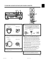
Quick automatic-search tuning (AUTOMATIC TUNING) is effective when station signals are strong and there is no interference.
However, if the signal from the station you want to select is weak, you must tune in to it manually (MANUAL TUNING).
2 3
1
AUTOMATIC TUNING
MANUAL TUNING
Set the SELECTOR DIAL to the AMP/TUN position on the remote control and select TUNER as the input source.
1
Select the reception band (FM or AM) and confirm it on
the display.
1
Front panel
Select the reception band (FM or AM) and confirm it on
the display.
Front panel
or
2
Press TUNING MODE so that the “AUTO TUNING”
indicator lights up on the display.
or
2
Press TUNING MODE.
Front panel
Front panel
Check that the “AUTO
TUNING” indicator goes off.
Lights up
3
To tune in to a higher frequency, press the UP side of
TUNING once.
To tune in to a lower frequency, press the DOWN side
of TUNING once.
3
Tune in manually to the desired station.
Front panel
Front panel
* To continue the tuning search, press and hold the button.
* If the station where the tuning search stops is not the
desired one, press once more.
* If the tuning search does not stop at the desired station
(because the signal from the station is weak), take the
manual tuning procedure.
Notes
• If you tune in manually to an FM station, it will be automatically received in monaural mode to increase the signal
quality.
• When tuned in to a station, the frequency of the received
station is shown on the display.
30
01RX-V595a-e/f3
30
6/24/99, 11:44 AM
English
MANUAL PRESET TUNING
This unit can store station frequencies to be selected by tuning. With this function, you can recall any desired station simply by
selecting the preset station number with which it was stored. Up to 40 stations (8 stations x 5 groups) can be stored.
2
4
3
To store stations
1
2
Tune in to the desired station.
(See page 30 for the tuning procedure.)
4
Select the preset station number with which you want to
store the station before the “MEMORY” indicator goes
off from the display.
Front panel
Press A/B/C/D/E once or more to select the desired
group (A to E) of preset stations and confirm it on the
display.
Front panel
3
The displayed station has been stored as A1.
Press MEMORY so that the “MEMORY” indicator
flashes for about five seconds.
Front panel
* In the same way, store other stations as A2, A3 ... A8.
* You can store more stations as preset station numbers in
other groups in the same way by selecting another group
in step 2.
Flashes
31
01RX-V595a-e/f3
31
6/24/99, 11:44 AM