1
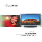
Your Gateway 30" LCD TV
user'sguide
Setting up
Troubleshooting
Contents
1 Introducing Your Gateway LCD TV . . . . . . . . . . . . . . . . . . . . . . . . . . . . . . . 1
Features . . . . . . . . . . . . . . . . . . . . . . . . . . . . . . . . . . . . . . . . . . . . . . . . . . . . . . . . . . . 2
Important Safeguards . . . . . . . . . . . . . . . . . . . . . . . . . . . . . . . . . . . . . . . . . . . . . . . . 3
Package contents . . . . . . . . . . . . . . . . . . . . . . . . . . . . . . . . . . . . . . . . . . . . . . . . . . . 5
Optional speaker package contents . . . . . . . . . . . . . . . . . . . . . . . . . . . . . . . . . . 7
Accessories . . . . . . . . . . . . . . . . . . . . . . . . . . . . . . . . . . . . . . . . . . . . . . . . . . . . . . . . 8
Turning on the main power . . . . . . . . . . . . . . . . . . . . . . . . . . . . . . . . . . . . . . . . . . . . 9
Front panel controls . . . . . . . . . . . . . . . . . . . . . . . . . . . . . . . . . . . . . . . . . . . . . . . . . 11
Back connections . . . . . . . . . . . . . . . . . . . . . . . . . . . . . . . . . . . . . . . . . . . . . . . . . . 13
2 Connecting Components . . . . . . . . . . . . . . . . . . . . . . . . . . . . . . . . . . . . . . . 15
Understanding video connections . . . . . . . . . . . . . . . . . . . . . . . . . . . . . . . . . . . . . .
Connecting your DVD player . . . . . . . . . . . . . . . . . . . . . . . . . . . . . . . . . . . . . . . . . .
Using component DVD video . . . . . . . . . . . . . . . . . . . . . . . . . . . . . . . . . . . . . .
Using S-Video . . . . . . . . . . . . . . . . . . . . . . . . . . . . . . . . . . . . . . . . . . . . . . . . . .
Using composite video . . . . . . . . . . . . . . . . . . . . . . . . . . . . . . . . . . . . . . . . . . .
Connecting your HDTV set-top box . . . . . . . . . . . . . . . . . . . . . . . . . . . . . . . . . . . .
Using component video . . . . . . . . . . . . . . . . . . . . . . . . . . . . . . . . . . . . . . . . . .
Connecting your VCR or video camera . . . . . . . . . . . . . . . . . . . . . . . . . . . . . . . . .
Using S-Video . . . . . . . . . . . . . . . . . . . . . . . . . . . . . . . . . . . . . . . . . . . . . . . . . .
Using composite video . . . . . . . . . . . . . . . . . . . . . . . . . . . . . . . . . . . . . . . . . . .
Using coaxial (RF) . . . . . . . . . . . . . . . . . . . . . . . . . . . . . . . . . . . . . . . . . . . . . .
Connecting off-air TV or cable TV . . . . . . . . . . . . . . . . . . . . . . . . . . . . . . . . . . . . .
Connecting speakers . . . . . . . . . . . . . . . . . . . . . . . . . . . . . . . . . . . . . . . . . . . . . . . .
Connecting a computer . . . . . . . . . . . . . . . . . . . . . . . . . . . . . . . . . . . . . . . . . . . . . .
Using DVI video . . . . . . . . . . . . . . . . . . . . . . . . . . . . . . . . . . . . . . . . . . . . . . . .
Using RGB video . . . . . . . . . . . . . . . . . . . . . . . . . . . . . . . . . . . . . . . . . . . . . . .
16
17
17
18
19
20
20
21
21
22
23
24
25
27
27
28
3 Adjusting Your LCD TV Settings . . . . . . . . . . . . . . . . . . . . . . . . . . . . . . . . 29
Using the OSD . . . . . . . . . . . . . . . . . . . . . . . . . . . . . . . . . . . . . . . . . . . . . . . . . . . . 30
OSD menus and options . . . . . . . . . . . . . . . . . . . . . . . . . . . . . . . . . . . . . . . . . 31
Using PIP/POP/PBP . . . . . . . . . . . . . . . . . . . . . . . . . . . . . . . . . . . . . . . . . . . . . 40
4 Maintenance and Troubleshooting . . . . . . . . . . . . . . . . . . . . . . . . . . . . . . 41
Cleaning and maintenance . . . . . . . . . . . . . . . . . . . . . . . . . . . . . . . . . . . . . . . . . . .
Cleaning the screen . . . . . . . . . . . . . . . . . . . . . . . . . . . . . . . . . . . . . . . . . . . . .
Cleaning the exterior . . . . . . . . . . . . . . . . . . . . . . . . . . . . . . . . . . . . . . . . . . . . .
Troubleshooting . . . . . . . . . . . . . . . . . . . . . . . . . . . . . . . . . . . . . . . . . . . . . . . . . . . .
42
42
42
43
i
Telephone support . . . . . . . . . . . . . . . . . . . . . . . . . . . . . . . . . . . . . . . . . . . . . . .44
A Safety, Regulatory, and Legal Information . . . . . . . . . . . . . . . . . . . . . . .45
Index . . . . . . . . . . . . . . . . . . . . . . . . . . . . . . . . . . . . . . . . . . . . . . . . . . . . . . . . . . . . . . 51
ii
Introducing Your
Gateway LCD TV
1
This chapter provides basic information about your
Gateway LCD TV.
Read this chapter to learn about:
■
Features
■
Warnings and safeguards
■
Package contents
■
Controls and connections
1
Chapter 1: Introducing Your Gateway LCD TV
Features
Your LCD TV features:
2
■
A bright, flicker-free image
■
Automatic detection and conversion of film content for correct display
with minimal motion artifacts (noise)
■
Accurate color processing
■
Two component video input sources that automatically synchronize the
display to match the incoming source
■
Picture-in-picture (PIP), picture-on-picture (POP), and picture-by-picture
(PBP) modes that let you watch two programs simultaneously
■
HDTV signal compatibility using an external HDTV decoder with
component video outputs
■
Digital zoom mode
■
A built-in BBE® sound processor that maximizes the sound quality
■
A built-in SRS® sound processor that simulates “surround” effects using
only two speakers
■
Connections for adding optional speakers
■
A built-in Digital Visual Interface (DVI) to eliminate the need for
digital-to-analog conversion
■
1280 × 1024 SXGA support for computer input
■
480p support for EDTV signals
■
720p and 1080i support for HDTV signals
www.gateway.com
Important Safeguards
Important Safeguards
Warning
Risk of electric shock - Do not open
To reduce the risk of electric shock, do not remove the back
cover. There are no user-serviceable parts inside.
Removing the back cover voids the warranty.
Have your LCD TV repaired by qualified service personnel
only.
Warnings and precautions
■
Do not place your hands, face, or objects close to the ventilation openings
of your LCD TV. The top of your LCD TV gets very hot from exhaust air
that is released through the ventilation openings. Burns or personal
injuries may occur if you are too close to the LCD TV. Damage may occur
if you place any object near the top of your LCD TV.
■
Disconnect all cables before moving your LCD TV. Moving your LCD TV
with its cables attached may damage the cables and cause fire or electric
shock danger.
■
Do not expose your LCD TV to rain or moisture.
■
Keep your LCD TV away from excessive dust, high temperatures, moisture,
or direct sunlight.
■
Use your LCD TV in a well-ventilated area and do not cover the ventilation
openings.
■
Do not modify your LCD TV or use an unshielded power cord or video
input source cable, or you may experience excessive interference.
■
Disconnect your LCD TV and unplug the power cord when the TV is not
used for a long period of time.
■
If the picture displayed is in any way abnormal, turn off your LCD TV, then
disconnect it from the electrical outlet. Make sure that your video input
source cable is connected correctly, then reconnect your LCD TV to the
electrical outlet.
■
Disconnect your LCD TV from the electrical outlet before cleaning or
performing maintenance. Do not use liquid or aerosol cleaners. Use only
a slightly damp cloth for cleaning.
■
Do not place your LCD TV on an unstable cart, stand, or table. Your
LCD TV may fall, causing serious damage.
www.gateway.com
3
Chapter 1: Introducing Your Gateway LCD TV
4
■
Do not place your LCD TV on a bed, sofa, rug, or other similar surfaces.
■
Never place your LCD TV near or over a radiator or heat source.
■
Do not install your LCD TV in an enclosed area unless correct ventilation
is provided.
■
Your LCD TV should be operated from the type of power source indicated
on the label. If the type of available power is unknown, consult your
electrician or local power company.
■
Your LCD TV is equipped with a 3-pin grounded plug. The plug will only
fit into a grounded power outlet. This is a safety feature. If you cannot
plug the power cord into the outlet, contact your electrician. Do not alter
the plug because this will defeat the safety feature.
■
Do not rest objects on the power cord and avoid placing the power cord
near high traffic areas.
■
Do not overload wall outlets and extension cords because this can result
in a risk of fire or electric shock.
■
Unplug your LCD TV and contact qualified service personnel if:
■
The power cord or plug is damaged or frayed.
■
Liquid has been spilled into your LCD TV.
■
Your LCD TV has been exposed to water or moisture.
■
Your LCD TV does not operate normally when the operating
instructions are followed. Adjust only those controls that are covered
by the operating instructions. Incorrect adjustment of other controls
may result in damage which often requires extensive work by a
qualified technician to restore your LCD TV to normal operation.
■
Your LCD TV has been dropped or the cabinet has been damaged.
www.gateway.com
Package contents
Package contents
Along with your LCD TV, the packaging box contains the following items:
Remote control
Two AA batteries
CATV cable
www.gateway.com
5
Chapter 1: Introducing Your Gateway LCD TV
Composite cable
(AV cable)
Power cord
User guide
Remote control
user guide
6
www.gateway.com
Package contents
Optional speaker package contents
Along with your optional speakers, the speaker packaging box contains the
following items:
Mounting
brackets
- And -
Screws
Audio cables
www.gateway.com
7
Chapter 1: Introducing Your Gateway LCD TV
Accessories
You can purchase these optional accessories for your LCD TV:
■
Cable kits. Gateway cable kits consist of high-quality gold cables of various
lengths, including:
■
DVI-D video cable
■
RCA audio cable
■
RCA component video cable
■
RCA composite video cable
■
S-Video cable
■
VGA video cable
■
Speakers. Two 8 watt speakers that can be mounted to your LCD TV.
■
Wall mount kit. The wall mount kit contains all of the required hardware
for mounting your LCD TV on your wall. (Gateway recommends you use
a qualified installer.) For more information, see the Wall Mount Installation
Guide at www.support.gateway.com/support/manlib/.
Contact Gateway for these and other accessories.
8
www.gateway.com
Turning on the main power
Turning on the main power
To turn on the power:
1
Connect the power cord to the power cord connector on the back of your
LCD TV, then plug the other end of the power cord into a correctly
grounded electrical outlet or surge protector.
www.gateway.com
9
Chapter 1: Introducing Your Gateway LCD TV
2
Press the MAIN switch. The status LED on the front turns yellow and your
LCD TV is ready to turn on.
3
Press the
button on the front of your LCD TV. The Status LED on the
front turns green.
Warning
10
For added protection during a lightning storm or when it
is left unattended or unused for long periods of time,
unplug your LCD TV from the wall outlet and disconnect
the antenna or cable system.
www.gateway.com
Front panel controls
Front panel controls
Main
Power
Switch
Input
Channel
and
Menu
Select
Volume
and
www.gateway.com
Status
LED
Power
Remote
Control
Sensor
11
Chapter 1: Introducing Your Gateway LCD TV
Button
Description
Main power switch
Turns main power off and on.
Input
Switches between available input sources.
Menu
Opens and closes the OSD.
Channel
and
Changes the channel.
OSD active: Selects on-screen display (OSD) options. For more
information, see “Using the OSD” on page 30.
Volume
and
Increases or decreases the volume.
OSD active: Adjusts on-screen display (OSD) options. For more
information, see “Using the OSD” on page 30.
Select
Confirms selections in the OSD. For more information, see “Using
the OSD” on page 30.
Power
Turns your LCD TV on and off after the MAIN switch is turned on.
When you turn your LCD TV on or off, wait three seconds before
pressing this button again.
Status LED
■
■
■
Remote control sensor
12
Not lit - No AC power detected. The MAIN switch is off or the power
cord is not connected.
Solid Yellow - The MAIN switch is on and your LCD TV is off.
Solid Green - Your LCD TV is on.
Receives signals from the remote control. Do not block.
www.gateway.com
Back connections
Back connections
PC Audio in
Headphone jack
Component Video 1/
Audio In
S-Video
Composite AV OUT
Video/Audio out
Composite AV IN
Video/Audio in
Component HDTV
Video/Audio in
Component DVD
Video/Audio in
Connector
Description
Composite
Video/Audio in
Connects to a composite audio/video device, such as a VCR or DVD
player.
Component HDTV
Video/Audio in
Connects to a component video device, such as an HDTV set-top box or
progressive-scan DVD player. Supports 480i, 480p, 720p, and 1080i
signals.
PC Audio in
Connects to your computer’s audio out jack.
Headphone jack
Plug headphones in here. The optional speakers are disabled.
S-Video
Connects to an S-Video device, such as a VCR, satellite dish receiver,
or digital cable box.
Composite
Video/Audio out
Connects to a video device, such as a VCR.
Component DVD
Video/Audio in
Connects to a component video device, such as a DVD player. Supports
480i signals only.
www.gateway.com
13
Chapter 1: Introducing Your Gateway LCD TV
RS-232
14
DVI in
RGB in
Antenna
Connector
Description
RS-232
Connects to a computer using customized software
(typically used by business, education, or government).
For more information see the RS-232 Serial Connection
Technical Reference at
www.support.gateway.com/support/manlib/.
DVI in
Connects to a DVI video device, such as a computer or
set-top box.
RGB in
Connects to an RGB video device, such as a computer
or set-top box.
Antenna
Connects to a VHF/UHF antenna or cable TV.
www.gateway.com
Connecting
Components
2
Read this chapter to learn how to connect:
■
DVD players
■
HDTV decoder set-top boxes
■
VCRs
■
Off-air TV and cable TV
■
Speakers
■
Computers
Warning
Before connecting any external
components, unplug your LCD TV.
15
Chapter 2: Connecting Components
Understanding video connections
Your LCD TV has four types of standard video connections. You should use the
best connection available to get the best display. For example, if your DVD
player supports a component video connection, connect the DVD player to
your LCD TV using component video instead of composite video or S-Video.
Connection
Quality
Cable and Connector
Description
Basic
Coaxial (RF). The video and audio signals
are both carried in one cable (the other three
connection types only handle video, and
require separate connections for sound).
Coaxial is the only way to connect an
antenna to your LCD TV.
Good
Composite. The video signal is carried
through a single “pin.” This connection
method is the one that is most commonly
found on devices.
Better
S-Video. The video signal is split into two
signals, black-and-white and color. Text
displayed on-screen through this connection
will be noticeably sharper then composite or
coaxial (RF).
Best
Component. The video signal is split into
three signals, two color, and one
black-and-white. Use component video to
take advantage of the superior picture
provided by signal sources such as HDTV
and progressive DVD.
16
www.gateway.com
Connecting your DVD player
Connecting your DVD player
If you have a progressive-scan DVD player, connect it using Component
DVD Video/Audio in. Make sure that you set your DVD to interlaced mode. For
information, see the documentation that came with your DVD player.
Using component DVD video
To connect your DVD player using component DVD video:
1
Connect the green-colored Y jack on the back of your DVD player to the
green-colored DVD Y jack on the back of your LCD TV.
2
Connect the red-colored PR or CR jack on the back of your DVD player to
the red-colored DVD PR jack on the back of your LCD TV.
3
Connect the blue-colored PB or CB jack on the back of your DVD player
to the blue-colored DVD PB jack on the back of your LCD TV.
4
Connect the red (R) and white (L) audio jacks on the back of your DVD
player to the DVD R and L audio-in jacks on the back of your LCD TV.
5
On the front of your LCD TV, press the INPUT button, CHANNEL
to select DVD (Y, Cb, Cr), then press the SELECT button.
www.gateway.com
and
17
Chapter 2: Connecting Components
Using S-Video
To connect your DVD player using S-Video:
18
1
Connect the S-Video jack on the back of your DVD player to the S-VIDEO
jack on the back of your LCD TV.
2
Connect the red (R) and white (L) audio jacks on the back of your DVD
player to the AV IN R and L audio-in jacks on the back of your LCD TV.
3
On the front of your LCD TV, press the INPUT button, CHANNEL
to select VIDEO2 (S-VIDEO), then press the SELECT button.
www.gateway.com
and
Connecting your DVD player
Using composite video
To connect your DVD player using composite video:
1
Connect the yellow video jack on the back of your DVD player to the
yellow AV IN jack on the back of your LCD TV.
2
Connect the red (R) and white (L) audio jacks on the back of your DVD
player to the AV IN R and L audio-in jacks on the back of your LCD TV.
3
On the front of your LCD TV, press the INPUT button, CHANNEL
to select VIDEO1 (CVBS), then press the SELECT button.
www.gateway.com
and
19
Chapter 2: Connecting Components
Connecting your HDTV set-top box
Using component video
To connect your HDTV decoder set-top box using component video:
20
1
Connect the green Y jack on the back of your HDTV set-top box to the
green HDTV Y jack on the back of your LCD TV.
2
Connect the red PR or CR jack on the back of your HDTV set-top box to
the red HDTV PR jack on the back of your LCD TV.
3
Connect the blue PB or CB jack on the back of your HDTV set-top box to
the blue HDTV PB jack on the back of your LCD TV.
4
Connect the red (R) and white (L) audio jacks on the back of your HDTV
set-top box to the HDTV R and L audio-in jacks on the back of your
LCD TV.
5
On the front of your LCD TV, press the INPUT button, CHANNEL
to select HDTV (Y, Pb, Pr), then press the SELECT button.
www.gateway.com
and
Connecting your VCR or video camera
Connecting your VCR or video
camera
Using S-Video
To connect your VCR or video camera using S-Video:
- OR -
1
Connect the S-Video jack on the back of your VCR or video camera to the
S-VIDEO jack on the back of your LCD TV.
2
Connect the red (R) and white (L) audio jacks on the back of your VCR
or video camera to the AV IN R and L audio-in jacks on the back of your
LCD TV.
3
On the front of your LCD TV, press the INPUT button, CHANNEL
to select VIDEO2 (S-VIDEO), then press the SELECT button.
www.gateway.com
and
21
Chapter 2: Connecting Components
Using composite video
To connect your VCR or video camera using composite video:
- OR -
22
1
Connect the yellow video jack on the back of your VCR or video camera
to the yellow AV IN jack on the back of your LCD TV.
2
Connect the red (R) and white (L) audio jacks on the back of your VCR
or video camera to the AV IN R and L audio-in jacks on the back of your
LCD TV.
3
On the front of your LCD TV, press the INPUT button, CHANNEL
to select VIDEO1 (CVBS), then press the SELECT button.
www.gateway.com
and
Connecting your VCR or video camera
Using coaxial (RF)
To connect your VCR using coaxial (RF) audio and video:
1
Connect the “output to TV” (RF out or Antenna out) jack on the back of
your VCR to the ANT jack on the back of your LCD TV.
2
On the front of your LCD TV, press the INPUT button, CHANNEL
to select TV, then press the SELECT button.
and
If you have an off-air antenna or cable box, connect your off-air antenna or
cable TV cable to the ANT connector on the back of your VCR.
Warning
If an outdoor antenna or cable system is connected to your
LCD TV, make sure that the antenna or cable system is
correctly grounded. For more information, see “Television
antenna connectors protection (for systems fitted with
TV/cable TV tuner cards)” on page 47.
www.gateway.com
23
Chapter 2: Connecting Components
Connecting off-air TV or cable TV
To connect off-air TV or cable TV using coaxial (RF) audio and video:
- OR -
1
Connect the coaxial (RF) connector from your antenna or cable box to the
ANT connector on the back of your LCD TV.
2
On the front of your LCD TV, press the INPUT button, CHANNEL
to select TV, then press the SELECT button.
and
If you have connected a VCR to the ANT connector on the back of your LCD TV,
connect your off-air TV or cable TV cable to the ANT connector on the back
of your VCR.
Warning
24
If an outdoor antenna or cable system is connected to your
LCD TV, make sure that the antenna or cable system is
correctly grounded. For more information, see “Television
antenna connectors protection (for systems fitted with
TV/cable TV tuner cards)” on page 47.
www.gateway.com
Connecting speakers
Connecting speakers
You can connect your LCD TV to a set of optional speakers using the SPEAKER
jacks located on the back of your LCD TV.
Leave the speakers free-standing with the attached speaker stands, or mount
them to the sides of your LCD. Make sure that you remove the stands before
mounting the speakers to the sides of your LCD TV.
To mount the optional speakers:
1
Secure the left speaker using one of each of the mounting brackets and
four (4) of the screws that came with the speakers.
www.gateway.com
25
Chapter 2: Connecting Components
2
Secure the right speaker using one of each of the mounting brackets and
four (4) of the screws that came with the speakers.
To connect the optional speakers:
■
26
Connect the audio jacks on the back of your speakers to the matching jacks
on the back of your LCD TV.
www.gateway.com
Connecting a computer
Connecting a computer
Using DVI video
To connect your computer using DVI video:
1
Connect the DVI connector on your computer to the DVI-In connector
on the back of your LCD TV.
2
Connect the Audio Out jack on your computer to the PC Audio In jack on
the back of your LCD TV. See “Back connections” on page 13 for the
location of the PC Audio In jack.
3
On the front of your LCD TV, press the INPUT button, CHANNEL
to select DVI DIGITAL, then press the SELECT button.
www.gateway.com
and
27
Chapter 2: Connecting Components
Using RGB video
To connect your computer using RGB video:
28
1
Connect the 15-pin D-Sub RGB connector on your computer to the RGB-IN
connector on the back of your LCD TV.
2
Connect the Audio Out jack on your computer to the PC Audio In jack on
the back of your LCD TV. See “Back connections” on page 13 for the
location of the PC Audio In jack.
3
On the front of your LCD TV, press the INPUT button, CHANNEL
to select DSUB ANALOG, then press the SELECT button.
www.gateway.com
and
Adjusting Your
LCD TV Settings
3
Read this chapter to learn how to adjust your LCD TV
settings from the on-screen display (OSD).
You can also use your remote control to change some
settings. For more information, see Your Gateway Remote
Control User’s Guide.
29
Chapter 3: Adjusting Your LCD TV Settings
Using the OSD
Your LCD TV features an on-screen display (OSD) that lets you adjust and save
contrast, brightness, and other settings. Your LCD TV saves changes you make
to the settings, even if you turn off your TV.
To adjust settings from the OSD:
1
2
Press the MENU button on the front of your LCD TV. The OSD opens.
3
4
Press the SELECT button on the front of your LCD TV to open the menu.
5
Press the VOLUME
the option setting.
6
Press the SELECT button on the front of your LCD TV to return to the
previous menu option.
Press the CHANNEL and
the menu you want.
buttons on the front of your LCD TV to select
Press the CHANNEL and
buttons on the front of your LCD TV to select
the menu option you want.
or
buttons on the front of your LCD TV to adjust
- OR Press the EXIT button to close the OSD.
30
www.gateway.com
Using the OSD
OSD menus and options
You can use these OSD menus and options to adjust various settings for your
LCD TV.
OSD Menu
Description
CHANNEL SETUP
This menu is only available in TV mode.
CH
AUTO CHANNEL. When this option is
selected, your LCD TV adds all channels that
have a signal to the channel list.
CHANNEL SETUP
CHANNEL. Changes the TV channel.
AUTO CHANNEL
CHANNEL
SELECT
ADD/DEL CH
SELECT. Sets the source for the tuner.
OFF
42
CABLE
ADD
Select CABLE (for cable or a satellite dish) or
ANTENNA.
ADD/DEL CH. Adds or removes the current
channel to the channel list.
VIDEO
CH
PSM. Choose between USER, GAME,
STANDARD, DYNAMIC, MILD preset video
modes.
VIDEO
CONTRAST. Adjusts the contrast of the
picture.
PSM
CONTRAST
BRIGHTNESS
SHARPNESS
COLOR
TINT
USER
70
45
45
50
-5
The PSM option must be set to USER to use
this option.
BRIGHTNESS. Adjusts the brightness of the
picture.
The PSM option must be set to USER to use
this option.
SHARPNESS. Adjust the amount of detail
enhancement.
The PSM option must be set to USER to use
this option.
COLOR. Adjusts the color saturation making
colors more intense.
The PSM option must be set to USER to use
this option.
TINT. Adjusts the color of flesh tones.
The PSM option must be set to USER to use
this option.
www.gateway.com
31
Chapter 3: Adjusting Your LCD TV Settings
OSD Menu
Description
AUDIO
SSM. Choose between USER, FLAT, MOVIE,
MUSIC and SPORTS preset audio modes.
AVL. Automatic volume leveling keeps
volume levels the same between different
programs.
AUDIO
CH
SSM
AVL
SRS WOW
SOUND
MUTE
BALANCE
BASS
TREBLE
USER
OFF
OFF
STEREO
OFF
SRS WOW. Simulates surround sound.
0
50
50
SOUND. Changes the sound output for
TV programs. Switch between STEREO,
SAP (Second Audio Program), or MONO for
audio simulcasts. The TV program must
support the output option.
MUTE. Turns the sound on and off.
BALANCE. Adjusts the balance level
between the speakers.
BASS. Adjusts the bass.
The SSM option must be set to USER to use
this option.
TREBLE. Adjusts the treble.
The SSM option must be set to USER to use
this option.
SETUP
CH
LANGUAGE. Changes the language of the
OSD menu. Choose between English,
German, French, Spanish, Italian, or Korean.
SETUP
LANGUAGE
ASPECT RATIO
OSD POSITION
TRANSPARENCY
ZOOM
RESET
ASPECT RATIO. Adjusts the screen width to
1:1, 16:9, 4:3 or PANORAMA viewing mode.
ENGLISH
16:9
20
OFF
OSD POSITION. Adjusts the position of the
OSD within the display image.
TRANSPARANCY. Adjusts the OSD menu
background transparency.
ZOOM. Moves or stretches the display image
when the screen width is set to 16:9 mode.
RESET. Resets picture settings to the factory
default.
32
www.gateway.com
Using the OSD
OSD Menu
Description
PIP/POP/PBP
PIP MODE. Selects the PIP
(picture-in-picture) sub-menu.
PIP/POP/PBP
CH
PBP MODE. Selects the PBP
(picture-by-picture) sub-menu.
PIP MODE
POP MODE
PBP MODE
PIP MODE sub-menu
CH
PIP/POP/PBP
PIP ON/OFF
PIP SOURCE
PIP SIZE
PIP IMAGE
PIP SOUND
PIP SWAP
POP MODE. Selects the POP
(picture-on-picture) sub-menu.
ON
DVI
SMALL
OFF
OFF
PIP ON/OFF. Turns PIP mode on or off. When
PIP is turned on, you can display two pictures
at one time. One picture is displayed on the
full screen and the other picture is displayed
in a small window. The picture on the full
screen is the main picture. The picture in the
window is the sub-picture.
For information about PIP/POP/PBP video
sources, see “Using PIP/POP/PBP” on
page 40.
PIP SOURCE. Changes the video input
source of the sub-picture when PIP is turned
on.
PIP SIZE. Changes the size of the
sub-picture.
PIP IMAGE. This option controls:
PIP POSITION. Moves the sub-picture
within the screen.
■
PIP CONTRAST. Adjusts the contrast of the
sub-picture.
■ PIP BRIGHTNESS. Adjusts the brightness
of the sub-picture.
PIP SOUND. Controls the audio of the
sub-picture.
■
PIP SWAP. Swaps the main picture and the
sub-picture.
www.gateway.com
33
Chapter 3: Adjusting Your LCD TV Settings
OSD Menu
Description
POP MODE sub-menu
POP ON/OFF. Turns POP mode on or off.
When POP is turned on, the screen is split
into two pictures. The picture on the left side
of your screen is the main picture. The
smaller picture on the right side of the screen
is the sub-picture.
CH
PIP/POP/PBP
POP ON/OFF
POP SOURCE
POP IMAGE
POP SOUND
POP SWAP
ON
DVI
OFF
OFF
For information about PIP/POP/PBP video
sources, see “Using PIP/POP/PBP” on
page 40.
POP SOURCE. Changes the video input
source of the sub-picture when POP is turned
on.
POP IMAGE. This option controls:
POP CONTRAST. Adjusts the contrast of
the sub-picture.
■
POP BRIGHTNESS. Adjusts the brightness
of the sub-picture.
POP SOUND. Controls the audio of the
sub-picture.
■
POP SWAP. Swaps the main picture and the
sub-picture.
34
www.gateway.com
Using the OSD
OSD Menu
Description
PBP MODE sub-menu
PBP ON/OFF. Turns PBP mode on or off.
When PBP is turned on, the screen is split
into two equal pictures. The picture on the left
side of your screen is the main picture. The
picture on the right side of the screen is the
sub-picture.
PIP/POP/PBP
CH
PBP ON/OFF
PBP SOURCE
PBP SIZE
PBP IMAGE
PBP SOUND
PBP SWAP
ON
DVI
FULL
For information about PIP/POP/PBP video
sources, see “Using PIP/POP/PBP” on
page 40.
OFF
OFF
PBP SOURCE. Changes the video input
source of the sub-picture when PBP is turned
on.
PBP SIZE. Changes the screen width from
FULL to 4:3 for the main picture and
sub-picture.
PBP IMAGE. This option controls:
PBP CONTRAST. Adjusts the contrast of
the sub-picture.
■
PBP BRIGHTNESS. Adjusts the brightness
of the sub-picture.
PBP SOUND. Controls the audio of the
sub-picture.
■
PBP SWAP. Swaps the main picture and the
sub-picture.
CAPTION & OPTION
CH
CAPTION/TEXT. Selects the closed
captioning text option.
CAPTION & OPTION
CAPTION/TEXT
CAPTION
KEY LOCK
PARENTAL
CAPTIONS. Turns captioning on and off.
EZ MUTE automatically turns captioning on
when your LCD TV is muted.
CCI
EZ MUTE
OFF
KEY LOCK. Locks out all buttons on the front
of your LCD TV except the power button.
When this option is on, you need to use the
remote control to control your LCD TV.
PARENTAL. Activates parental controls. You
need the remote control to use this option. For
more information, see Your Gateway Remote
Control User’s Guide.
www.gateway.com
35
Chapter 3: Adjusting Your LCD TV Settings
You can use these OSD menus and options to adjust various settings when your
computer is connected to your LCD TV.
OSD Menu
Description
ADJUSTMENT
CONTRAST. Adjusts the contrast of the
picture.
ADJUSTMENT
CONTRAST
BRIGHTNESS
COLOR
BRIGHTNESS. Adjusts the brightness of the
picture.
76
64
TRACKING
You may need to readjust brightness after the
LCD TV warms up.
COLOR. Adjusts the color temperature to
three preset modes. You can also customize
the red, green and blue separately.
AUTO. Adjusts the screen width to fill the
screen or to display one-to-one.
TRACKING
AUTO
CLOCK
PHASE
H POSITION
V POSITION
CLOCK. Adjusts your LCD TV to match the
video input source.
OFF
50
0
50
34
PHASE. Removes any horizontal distortion
and clears or sharpens the displayed
characters.
H POSITION. Adjusts the horizontal screen
position.
V POSITION. Adjusts the vertical screen
position.
36
www.gateway.com
Using the OSD
OSD Menu
Description
AUDIO
SSM. Choose between USER, FLAT, MOVIE,
MUSIC and SPORTS preset audio modes.
AUDIO
SSM
AVL
MUTE
SRS WOW
BALANCE
BASS
TREBLE
AVL. Automatic volume leveling keeps
volume levels the same between different
programs.
USER
OFF
OFF
OFF
MUTE. Turns the sound on and off.
SRS WOW. Simulates surround sound.
0
50
50
BALANCE. Adjusts the balance level
between the speakers.
BASS. Adjusts the bass.
The SSM option must be set to USER to use
this option.
TREBLE. Adjusts the treble.
The SSM option must be set to USER to use
this option.
SETUP
LANGUAGE. Changes the language of the
OSD menu. Choose between English,
German, French, Spanish, Italian, or Korean.
SETUP
LANGUAGE
ASPECT RATIO
OSD POSITION
TRANSPARENCY
ZOOM
RESET
ASPECT RATIO. Adjusts the screen width to
1:1, 16:9, 4:3 or PANORAMA viewing mode.
ENGLISH
16:9
20
OFF
1280 X 720 @ 60Hz
OSD POSITION. Adjusts the position of the
OSD within the display image.
TRANSPARANCY. Adjusts the OSD menu
background transparency.
ZOOM. Moves or stretches the display image
when the screen width is set to FULL mode.
RESET. Resets picture settings to the factory
default.
www.gateway.com
37
Chapter 3: Adjusting Your LCD TV Settings
OSD Menu
Description
PIP/POP/PBP
PIP MODE. Selects the PIP
(picture-in-picture) sub-menu.
PIP/POP/PBP
CH
PBP MODE. Selects the PBP
(picture-by-picture) sub-menu.
PIP MODE
POP MODE
PBP MODE
PIP MODE sub-menu
CH
PIP/POP/PBP
PIP ON/OFF
PIP SOURCE
PIP SIZE
PIP IMAGE
PIP SOUND
PIP SWAP
POP MODE. Selects the POP
(picture-on-picture) sub-menu.
ON
DVI
SMALL
OFF
OFF
PIP ON/OFF. Turns PIP mode on or off. When
PIP is turned on, you can display two pictures
at one time. One picture is displayed on the
full screen and the other picture is displayed
in a small window. The picture on the full
screen is the main picture. The picture in the
window is the sub-picture.
For information about PIP/POP/PBP video
sources, see “Using PIP/POP/PBP” on
page 40.
PIP SOURCE. Changes the video input
source of the sub-picture when PIP is turned
on.
PIP SIZE. Changes the size of the
sub-picture.
PIP IMAGE. This option controls
CONTRAST, BRIGHTNESS, SHARPNESS,
COLOR and TINT for the sub-picture.
PIP SOUND. Controls the audio of the
sub-picture.
PIP SWAP. Swaps the picture and the
sub-picture.
38
www.gateway.com
Using the OSD
OSD Menu
Description
POP MODE sub-menu
POP ON/OFF. Turns POP mode on or off.
When POP is turned on, the screen is split
into two pictures. The picture on the left side
of your screen is the main picture. The
smaller picture on the right side of the screen
is the sub-picture.
PIP/POP/PBP
CH
POP ON/OFF
POP SOURCE
POP IMAGE
POP SOUND
POP SWAP
ON
DVI
OFF
OFF
For information about PIP/POP/PBP video
sources, see “Using PIP/POP/PBP” on
page 40.
POP SOURCE. Changes the video input
source of the sub-picture when POP is turned
on.
POP IMAGE. This option controls:
POP POSITION. Moves the sub-picture
within the screen.
POP SOUND. Controls the audio of the
sub-picture.
■
POP SWAP. Swaps the picture and the
sub-picture.
PBP MODE sub-menu
CH
PIP/POP/PBP
PBP ON/OFF
PBP SOURCE
PBP SIZE
PBP IMAGE
PBP SOUND
PBP SWAP
ON
DVI
SMALL
OFF
OFF
PBP ON/OFF. Turns PBP mode on or off.
When PBP is turned on, the screen is split
into two equal pictures. The picture on the left
side of your screen is the main picture. The
picture on the right side of the screen is the
sub-picture.
For information about PIP/POP/PBP video
sources, see “Using PIP/POP/PBP” on
page 40.
PBP SOURCE. Changes the video input
source of the sub-picture when PBP is turned
on.
PBP IMAGE. This option controls:
PBP POSITION. Moves the sub-picture
within the screen.
PBP SOUND. Controls the audio of the
sub-picture.
■
PBP SWAP. Swaps the picture and the
sub-picture.
www.gateway.com
39
Chapter 3: Adjusting Your LCD TV Settings
Using PIP/POP/PBP
Use the following table to determine what video sources you can select for the
main picture and sub-picture when you are using PIP, POP, or PBP modes.
Sub-Picture
Main Picture
TV
40
CVBS
S-VIDEO
DVD
HDTV
RGB
DVI
TV
X
X
X
CVBS
X
X
X
S-VIDEO
X
X
X
DVD
X
X
X
HDTV
X
X
X
X
X
RGB
X
X
X
X
X
DVI
X
X
X
X
www.gateway.com
X
Maintenance and
Troubleshooting
4
Read this chapter to learn how to maintain and
troubleshoot your LCD TV.
41
Chapter 4: Maintenance and Troubleshooting
Cleaning and maintenance
Cleaning the screen
■
Do not use substances such as glass cleaners, solvents, and thinners.
■
The screen of your LCD TV has been specially treated. Wipe the surface
gently using only a cleaning cloth or a soft, lint-free cloth.
■
If the surface is particular dirty, use a soft cloth and water to clean the
screen. Squirt a little water on the cloth (never directly on the screen), then
wipe the screen with the cloth.
Warning
The screen of your LCD TV is made of specially coated
glass and can be scratched or damaged by abrasive or
ammonia-based window cleaners.
Scratches on the bezel or glass are not covered by your
warranty.
■
Do not scratch or hit the surface of the screen with your fingers or any
hard objects.
Cleaning the exterior
42
■
Your LCD TV is cooled by air circulated through the vents on the case, so
keep the vents free of dust. With your LCD TV turned off and unplugged,
brush the dust away from the vents with a damp cloth. Be careful not to
drip any water into the vents. Do not attempt to clean dust from the inside
of your LCD TV.
■
Do not use abrasive or solvent cleaners because they can damage the finish
on components.
■
Do not allow any excessive water or moisture to come into contact with
the surface of your LCD TV. If water or moisture gets inside your LCD TV,
operating problems and electrical and shock hazards may result.
■
Do not scratch or hit the cabinet with your fingers or any hard objects.
■
Do not place articles made from rubber or PVC near the cabinet for any
extended periods of time.
www.gateway.com
Troubleshooting
Troubleshooting
Use the following information to solve common problems.
You cannot see a picture
■
Make sure that the power cord is plugged into a grounded electrical outlet.
■
Make sure that the main power switch and power button are turned on.
■
Make sure that the selected video input source is connected to a working
component.
■
If your LCD TV is connected to your computer in RGB mode, press any
key on your keyboard to “wake” your computer.
You see a distorted picture or hear unusual sound
■
You may be getting interference from electrical appliances, cars,
motorcycles, or fluorescent lights. Try moving your LCD TV to another
location.
■
Make sure that a DVD player connected to Component
DVD Video/Audio in is set to interlaced mode. See the documentation that
came with your DVD player.
The color is abnormal
■
Make sure that the input source cable is connected securely and correctly
to your LCD TV.
The picture has abnormal patterns
■
Make sure that the input source cable is attached securely and correctly.
■
Make sure that the video input source is within the range of your LCD TV.
Compare the video input source’s specifications with your LCD TV
specifications.
The display image does not cover the entire screen
■
If you are using DVI DIGITAL or DSUB ANALOG mode, make sure that
the ASPECT RATIO in the OSD is set correctly.
■
If you are using TV, VIDEO1, VIDEO2, DVD, or HDTV modes, make sure
that the ASPECT RATIO option in the OSD is set to the screen option you
want.
www.gateway.com
43
Chapter 4: Maintenance and Troubleshooting
You can see a picture but you cannot hear sound
■
Make sure that the volume is not turned down.
■
Make sure that the sound is not muted.
■
Make sure that your audio input source cables are connected securely and
correctly.
■
If you did not purchase the optional speakers, you must use headphones
or another component that is connected to AV out to hear sound.
The LCD TV has pixels that are always bright, dark, or colored
■
Your LCD TV is manufactured using an extremely high level of precision
technology. However, sometimes some pixels of your LCD TV may not
display correctly. Pixel defects within industry specifications are inherent
to this type of product and do not constitute a defective product.
You see “noise” or “trash” on the screen
■
When your LCD TV’s digital capabilities exceed a digital broadcast signal,
the signal is up-converted (increased) to match your LCD TV’s display
capabilities. Up-converting can cause noise or trash.
Screen brightness is diminished
■
Video display devices experience degradation of brightness over the life of
the device. Normal brightness degradation is not covered by your warranty.
Telephone support
If this troubleshooting information does not resolve your problem or if you
have other questions relating to your LCD TV, visit www.support.gateway.com.
You can also call our Service Center at 888-737-MyGW (6949).
44
www.gateway.com
Safety,
Regulatory, and
Legal Information
A
Regulatory compliance
statements
United States of America
Federal Communications Commission (FCC)
Unintentional emitter per FCC Part 15
This device has been tested and found to comply with the limits for a
Class B digital device, pursuant to Part 15 of the FCC rules. These limits
are designed to provide reasonable protection against harmful
interference in a residential installation.
45
Safety, Regulatory, and Legal Information
This equipment generates, uses, and can radiate radio frequency energy and, if not installed and
used in accordance with the instructions, may cause harmful interference to radio or television
reception. However, there is no guarantee that interference will not occur in a particular
installation. If this equipment does cause interference to radio and television reception, which can
be determined by turning the equipment off and on, the user is encouraged to try to correct the
interference by one or more of the following measures:
■
Reorient or relocate the receiving antenna
■
Increase the separation between the equipment and receiver
■
Connect the equipment to an outlet on a different circuit from that to which the receiver is
connected
■
Consult the dealer or an experienced radio/TV technician for help.
Compliance Accessories: The accessories associated with this equipment are: shielded video cable
when an external monitor is connected. These accessories are required to be used in order to
ensure compliance with FCC rules.
FCC declaration of conformity
Responsible party:
Gateway Companies, Inc.
610 Gateway Drive, North Sioux City, SD 57049
(605) 232-2000 Fax: (605) 232-2023
Product:
■
GTW-L30M103 LCD TV
This device complies with Part 15 of the FCC Rules. Operation of this product is subject to the
following two conditions: (1) this device may not cause harmful interference, and (2) this device
must accept any interference received, including interference that may cause undesired operation.
Caution
Changes or modifications not expressly approved by
Gateway could void the FCC compliance and negate your
authority to operate the product.
Canada
Industry Canada (IC)
Unintentional emitter per ICES-003
This digital apparatus does not exceed the Class B limits for radio noise emissions from digital
apparatus as set out in the radio interference regulations of Industry Canada.
Le présent appareil numérique n’émet pas de bruits radioélectriques dépassant les limites
applicables aux appareils numériques de Classe B prescrites dans le règlement sur le brouillage
radioélectrique édicté par Industrie Canada.
46
www.gateway.com
Regulatory compliance statements
California Proposition 65 Warning
Warning
This product contains chemicals, including lead, known to
the State of California to cause cancer and/or birth defects
or reproductive harm.
Television antenna connectors protection (for
systems fitted with TV/cable TV tuner cards)
External television antenna grounding
If an outside antenna or cable system is to be connected to your Gateway PC, make sure that the
antenna or cable system is electrically grounded to provide some protection against voltage surges
and static charges.
Article 810 of the National Electrical Code, ANSI/NFPSA 70, provides information with regard to
proper grounding of the mast and supporting structure, grounding of the lead-in wire to an
antenna discharge unit, size of grounding conductors, location of antenna discharge unit,
connection to grounding electrodes, and requirements for the grounding electrode.
Lightning protection
For added protection of any Gateway product during a lightning storm or when it is left
unattended or unused for long periods of time, unplug the product from the wall outlet and
disconnect the antenna or cable system.
www.gateway.com
47
Safety, Regulatory, and Legal Information
Power lines
Do not locate the antenna near overhead light or power circuits, or where it could fall into such
power lines or circuits.
Warning
When installing or realigning an outside antenna system,
extreme care should be taken to keep from touching such
power lines or circuits. Contact with them could be fatal.
7
6
5
4
3
1
2
Antenna and satellite grounding
48
Reference
Grounding component
1
Electric service equipment
2
Power service grounding electrode system (NEC Art 250, Part H)
3
Ground clamps
4
Grounding conductors (NEC Section 810-21)
5
Antenna discharge unit (NEC Section 810-20)
6
Ground clamp
7
Antenna lead-in wire
www.gateway.com
Notices
Notices
Copyright © 2003 Gateway, Inc.
All Rights Reserved
14303 Gateway Place
Poway, CA 92064 USA
All Rights Reserved
This publication is protected by copyright and all rights are reserved. No part of it may be reproduced or
transmitted by any means or in any form, without prior consent in writing from Gateway.
The information in this manual has been carefully checked and is believed to be accurate. However, changes are
made periodically. These changes are incorporated in newer publication editions. Gateway may improve and/or
change products described in this publication at any time. Due to continuing system improvements, Gateway is
not responsible for inaccurate information which may appear in this manual. For the latest product updates,
consult the Gateway Web site at www.gateway.com. In no event will Gateway be liable for direct, indirect, special,
exemplary, incidental, or consequential damages resulting from any defect or omission in this manual, even if
advised of the possibility of such damages.
In the interest of continued product development, Gateway reserves the right to make improvements in this
manual and the products it describes at any time, without notices or obligation.
Trademark Acknowledgments
1-800-GATEWAY, ActiveCPR, ALR, AnyKey, black-and-white spot design, CrystalScan, Destination, DestiVu, EZ
Pad, EZ Point, Field Mouse, Gateway 2000, Gateway Country, gateway.net, Gateway stylized logo, Perfect
Scholar, Solo, TelePath, Vivitron, stylized “G” design, and “You’ve got a friend in the business” slogan are
registered trademarks and black-and-white spotted box logo, GATEWAY, Gateway Astro, Gateway@Work,
Gateway Connected touch pad, Gateway Connected music player, Gateway Cyber:)Ware, Gateway
Education:)Ware, Gateway Flex Case, Gateway Gaming:)Ware, Gateway GoBack, Gateway Gold, Gateway
Learning:)Ware, Gateway Magazine, Gateway Micro Server, Gateway Money:)Ware, Gateway Music:)Ware,
Gateway Networking Solutions, Gateway Online Network (O.N.) solution, Gateway Photo:)Ware, Gateway
Professional PCs, Gateway Profile, Gateway Solo, green stylized GATEWAY, green stylized Gateway logo,
Gateway Teacher:)Ware, Gateway Video:)Ware, HelpSpot, InforManager, Just click it!, Learn@Gateway, Kids
BackPack, SERVE-TO-ORDER, Server Watchdog, the Spotted G Gateway Logo and the Spotted G Logo,
SpotShop, Spotshop.com, and Your:)Ware are trademarks of Gateway, Inc. Intel, Intel Inside logo, and Pentium
are registered trademarks and MMX is a trademark of Intel Corporation. Microsoft, MS, MS-DOS, and Windows
are trademarks or registered trademarks of Microsoft Corporation. All other product names mentioned herein are
used for identification purposes only, and may be the trademarks or registered trademarks of their respective
companies.
www.gateway.com
49
Safety, Regulatory, and Legal Information
50
www.gateway.com
Index
A
accessories 8
adjust
aspect ratio 32, 37
brightness 31, 36
color 31, 36
contrast 31, 36
sound 32, 37
TV settings 31, 36
adjustment menu 36
antenna connection 14
aspect ratio 32, 37
B
back panel connections 13
batteries 5
brightness 31, 36
C
cable
CATV 5
cable kits 8
cable TV
connecting coaxial (RF) 24
caption and option menu 35
CATV cable 5
channel buttons 12
channel setup menu 31
cleaning 42
exterior 42
screen 42
closed captioning 35
Coaxial (RF) video 16
coaxial (RF) video
connection 14
color 31, 36
component DVD video/audio in
connection 13
component HDTV video/audio in
connection 13
component video 16
component video/audio out connection
13
composite cable 6
composite video 16
computer
connecting 27
connecting DVI video 27
connecting RGB video 28
connecting
cable TV 24
computer 27
DVD player 17
HDTV decoder set-top box 20
off-air TV 24
power cord 9
speakers 25
VCR 21
video camera 21
connections
antenna 14
back panel 13
component DVD video/audio in 13
component HDTV video/audio in 13
DVI in 14
PC audio in 13
RGB in 14
RS-232 14
S-Video 13
video/audio in 13
video/audio out 13
contrast 31, 36
D
DVD player
connecting component video 17
connecting composite video 19
connecting S-Video 18
DVI
in connection 14
51
F
P
features 2
front panel buttons 11
parental controls 35
PBP mode 35, 39
PC audio in connection 13
PIP mode 33, 38
PIP/POP/PBP menu 33, 38
POP mode 34, 39
power
button 12
main switch 10
turning on 10
power cord 6
connection 9
H
HDTV decoder set-top box
connecting component video 20
headphone jack 13
I
Input button 12
L
left and right buttons 30
R
M
main power
switch 10
turning on 10
maintenance 41, 42
Menu button 12, 30
remote control 5
remote control sensor 12
Remote control user guide 6
RGB
in connection 14
RS-232 connection 14
O
S
off-air TV
connecting coaxial (RF) 24
on-screen display
see OSD
OSD 30
adjustment menu 36
aspect ratio 32, 37
audio menu 32, 37
brightness 31, 36
caption and option menu 35
channel menu 31
closed captioning 35
color 31, 36
contrast 31, 36
PIP mode 33, 34, 35, 38, 39
PIP/POP/PBP menu 33, 38
setup menu 32, 37
tracking menu 36
video menu 31
safety 3
select button 12
Service Center 44
setting up
safety precautions 3
setup menu 32, 37
sound menu 32, 37
speakers 8
connecting 25
mounting 25
status LED 12
support 44
S-Video 16
connection 13
52
T
tracking menu 36
troubleshooting 41, 43
V
VCR
connecting coaxial (RF) 23
connecting composite video 22
connecting S-Video 21
video camera
connecting composite video 22
connecting S-Video 21
video connections
types of 16
video menu 31
video/audio in connection 13
volume buttons 12
W
wall mount kit 8
53
54
MAN MON LG 30" LCD TV GDE R0 9/03