1
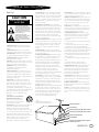
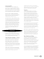
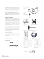
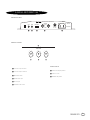
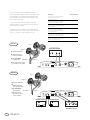
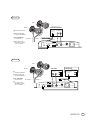
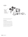
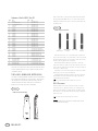
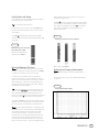
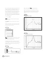
PRELUDE™ MTS
Owner’s Guide
CAUTION
RISK OF ELECTRIC SHOCK
DO NOT OPEN
WARNING: SHOCK HAZARD, DO NOT OPEN.
AVIS: RISQUE DE CHOC ELECTRIQUE – NE PAS OUVRIR.
CUIDADO: PELIGRO DE CHOQUE ELÉCTRICO – NO ABRIR.
CAUTION: TO REDUCE THE RISK OF ELECTRIC SHOCK
DO NOT REMOVE COVER (0R BACK)
NO USER SERVICEABLE PARTS INSIDE
REFER SERVICING TO QUALIFIED PERSONNEL
THIS INFINITY PRODUCT IS DESIGNED FOR 120-VOLT USE ONLY! FOR
DETAILED SAFETY PRECAUTIONS, PLEASE SEE FOLLOWING PAGE IN THIS
OWNER’S MANUAL FOR “IMPORTANT SAFETY INSTRUCTIONS.”
The lightning flash with arrowhead symbol, within an equilateral triangle, is
intended to alert the user to the presence of uninsulated “dangerous voltage” within
the product’s enclosure that may be of sufficient magnitude to constitute a risk of
electric shock to persons.
The exclamation point within an equilateral triangle is intended to alert the user
to the presence of important operating and maintenance (servicing) instructions in
the literature accompanying the product.
L’éclair avec le symbole de la flèche, placé dans les limites d’un triangel équilatéral est
prévu pour avertir l’utilisateur de la présence de “tension dangereuse” non isolée dans
l’enceinte du produit qui pourrait être d’une importance suffisante pour présenter un
risque d’électrocution aux personnes.
Le point d’exclamation dans un triangel équilateral est prévu pour avertir l’utilisateur
de la présence d’instructions importantes pour les opérations et l’entretien (service)
dans les manuels fournis avec l’appareil.
ATTENTION: POUR EVITER LES CHOCS ELECTRIQUES, INTRODUIRE
LA LAME LA PLUS LARGE DE LA FICHE DANS LA BORNE
CORRESPONDANTE DE LA PRISE ET POUSSER JUSQUAU FOND.
Este destello luminoso con un símbolo de punta de flecha dentro de un triángulo
equilátero tiene el objectivo de alertar al usuario sobre la presencia de “voltaje
peligroso” no aislado dentro de la caja del producto que puede ser de magnitud lo
suficientemente grande para constituir un riesgo de choque eléctrico para las personas.
Este punto de exclamación dentro de un triángulo equilátero tiene el objectivo de
alertar al usuario sobre la existencia de instrucciones operativas y de mantenimiento
(servicio) importantes en la literatura que acomaña el aparato.
CUIDADO: PARA REDUCIR EL RIESGO DE CHOQUE ELÉCTRICO, NO
RETIRE LA CUBIERTA (O RESPALDO). DENTRO NO HAY PEIZAS A LAS
QUE EL USUARIO PUEDE DAR SERVICIO. REMITA EL SERVICIO AL
PERSONAL DE SERVICIO CALIFICADO.
ii
PRELUDE MTS
IMPORTANT SAFETY PRECAUTIONS
Read First!
CAUTION
RISK OF ELECTRIC SHOCK
DO NOT OPEN
The lightning flash with arrowhead
symbol within an equilateral triangle is
intended to alert the user to the presence
of uninsulated “dangerous voltage” within
the product’s enclosure that may be of
sufficient magnitude to constitute a risk of
electric shock to persons.
The exclamation point within an
equilateral triangle is intended to alert the
user to the presence of important
operating and maintenance (servicing)
instructions in the literature accompanying
the appliance.
1. Read Instructions. All the safety and operating
instructions should be read before the product is
operated.
2. Retain Instructions. The safety and operating
instructions should be retained for future reference.
3. Heed Warnings. All warnings on the product and in
the operating instructions should be adhered to.
4. Follow Instructions. All operating and use
instructions should be followed.
5. Cleaning. Unplug this product from the wall outlet
before cleaning. Do not use liquid cleaners or aerosol
cleaners. Use a damp cloth for cleaning.
6. Attachments. Do not use attachments not
recommended by the product manufacturer,
as they may cause hazards.
7. Water and Moisture. To reduce the risk of fire or
electric shock, do not use this product outdoors or
near water–for example, near a bathtub, wash bowl,
kitchen sink or laundry tub; in a wet basement; near a
swimming pool; or the like.
8. Accessories. Do not place this product on an
unstable cart, stand, tripod, bracket or table.The
product may fall, causing serious injury to a child or
adult, and serious damage to the product. Use only
with a cart, stand, tripod, bracket or table
recommended by the manufacturer, or sold with the
product. Any mounting of the product should follow the
manufacturer’s instructions, and should use a
mounting accessory recommended by the
manufacturer.
9. A Product and Cart Combination
Should Be Moved with Care. Quick
stops, excessive force and uneven
surfaces may cause the product and
cart combination to overturn.
10. Ventilation. Slots and openings in the cabinet are
provided for ventilation and to ensure reliable
operation of the product and to protect it from
overheating, and these openings must not be blocked
or covered.The openings should never be blocked by
placing the product on a bed, sofa, rug or other
similar surface.This product should not be placed in a
built-in installation, such as a bookcase or rack,
unless proper ventilation is provided or the
manufacturer’s instructions have been adhered to.
11. Power Sources. This product should be operated
only from the type of power source indicated on the
marking label. If you are not sure of the type of power
supply to your home, consult your product dealer or
local power company. For products intended to operate
from battery power, or other sources, refer to the
operating instructions.
12. Grounding or Polarization. This product may be
equipped with a polarized alternating-current-line plug
(a plug having one blade wider than the other).This
plug will fit into the power outlet only one way.This is
a safety feature. If you are unable to insert the plug
fully into the outlet, try reversing the plug. If the plug
should still fail to fit, contact your electrician to
replace your obsolete outlet. Do not defeat the safety
purpose of the polarized plug.
13. Power-Cord Protection. Power-supply cords should
be routed so that they are not likely to be walked on or
pinched by items placed upon or against them, paying
particular attention to cords at plugs, convenience
receptacles, and the point where they exit from the
product.
14. Nonuse Periods. The power cord of the product
should be unplugged from the outlet when left unused
for long periods of time.
15. Outdoor Antenna Grounding. If an outside antenna
or cable system is connected to the product, be sure
the antenna or cable system is grounded so as to
provide some protection against voltage surges and
built-up static charges. Article 810 of the National
Electrical Code, ANSI/NFPA 70, provides information
with regard to proper grounding of the mast and
supporting structure, grounding of the lead-in wire to
an antenna discharge unit, size of grounding
conductors, location of antenna-discharge unit,
connection to grounding electrodes, and requirements
for the grounding electrode. See Figure A.
16. Lightning. For added protection for this product
during a lightning storm, or when it is left unattended
and unused for long periods of time, unplug it from
the wall outlet and disconnect the antenna or cable
system.This will prevent damage to the product due to
lightning and power-line surges.
17. Power Lines. An outside antenna system should not
be located in the vicinity of overhead power lines or
other electric light or power circuits, or where it can
fall into such power lines or circuits. When installing
an outside antenna system, extreme care should be
taken to keep from touching such power lines or
circuits, as contact with them might be fatal.
Figure A.
Example of Antenna Grounding as per
National Electrical Code ANSI/NFPA 70
18. Overloading. Do not overload wall outlets, extension
cords, or integral convenience receptacles, as this can
result in a risk of fire or electric shock.
19. Object and Liquid Entry. Never push objects of any
kind into this product through openings, as they may
touch dangerous voltage points or short-out parts that
could result in a fire or electric shock. Never spill
liquid of any kind on the product.
20. Servicing. Do not attempt to service this product
yourself, as opening or removing covers may expose
you to dangerous voltage or other hazards. Refer all
servicing to qualified service personnel.
21. Damage Requiring Service. Unplug this product
from the wall outlet and refer servicing to qualified
service personnel under the following conditions:
a. The power-supply cord or the plug has been
damaged; or
b. Objects have fallen onto, or liquid has been spilled
into, the product; or
c. The product has been exposed to rain or water; or
d. The product does not operate normally when
following the operating instructions. Adjust only those
controls that are covered by the operating instructions,
as an improper adjustment of other controls may
result in damage and will often require extensive work
by a qualified technician to restore the product to its
normal operation; or
e. The product has been dropped or damaged in any
way; or
f. The product exhibits a distinct change in
performance; this indicates a need for service.
22. Replacement Parts. When replacement parts are
required, be sure the service technician has used
replacement parts specified by the manufacturer or
that have the same characteristics as the original
part. Unauthorized substitutions may result in fire,
electric shock or other hazards.
23. Safety Check. Upon completion of any service or
repairs to this product, ask the service technician to
perform safety checks to determine that the product is
in proper operating condition.
24. Wall or Ceiling Mounting. The product should be
mounted to a wall or ceiling only as recommended by
the manufacturer.
25. Heat. The product should be situated away from
heat sources such as radiators, heat registers, stoves
or other products (including amplifiers) that produce
heat.
Antenna Lead-In Wire
Ground Clamp
Antenna Discharge Unit (NEC Section 810-20)
Grounding Conductors (NEC Section 810-21)
Electric Service Equipment
Ground Clamps
Power Service Grounding Electrode System
(NEC Art. 250, Part H)
PRELUDE MTS
iii
PRELUDE MTS OWNER’S GUIDE
Table of Contents
iv
PRELUDE MTS
ii
Caution
iii
Important Safety Precautions
1
Technology
1
Ceramic Metal Matrix Diaphragms™ (C.M.M.D.)
1
Transducers
1
Room-Friendly Acoustical Design
2
Completing the Experience
2
Unpacking the Product/Included Accessories
3
Installation of the Prelude System
3
Installing the Tower on Top of the Subwoofer
6
Placement of the Components
7
Controls and Connections
8
Connection Methods 1–4
11
Room Adaptive Bass Optimization System™ (R.A.B.O.S.)
12
Contents of the R.A.B.O.S.Test CD
12
The R.A.B.O.S. Sound-Level Meter (RSLM)
17
What You Measure, What To Do
20
Adjusting the R.A.B.O.S. Equalizer
21
Final System Balance
22
Maintenance and Service
23
Specifications
24
R.A.B.O.S. Measurement Templates
27
Notes
Infinity Prelude MTS
This loudspeaker system represents a refinement of the
principles that have guided Infinity’s loudspeaker designs for
more than 30 years. Loudspeaker development is generally an
evolutionary process. New models usually perform slightly better
than the ones they replace. Over time, the subtle improvements
add up and, when the latest model is compared to a loudspeaker
that is ten or twelve years old, the disparity is unmistakable.
Every once in a while, a loudspeaker is developed that
transcends this pattern – its performance so remarkable, its
design so stunning, its technology so advanced, it can truly be
described as revolutionary.The new Infinity Prelude MTS
loudspeaker system is an elegant case in point.
The Prelude MTS system is a 4-way loudspeaker with its midbass, midrange and high-frequency-driver array mounted atop a
12", 850-watt powered subwoofer. Outer beauty radiates from
a choice of polished wood veneers and a brushed, anodizedaluminum enclosure that would make an old-world furniture
craftsman proud. Its true splendor and magnificence, though,
come from the inside. With its proprietary Ceramic Metal Matrix
Diaphragms™
, powerful proprietary BASH® amplifiers and
sophisticated, yet refined, dividing networks, the Prelude MTS
will breathe life into any musical or cinematic performance
and touch the soul of the listener.The Prelude MTS is the
consummation of Infinity’s quest to apply “science in the
service of art.”
TECHNOLOGY
The Prelude MTS system incorporates several innovative
technologies that, when implemented by exceptional engineering
talent after hours upon hours of subjective listening evaluations,
result in a loudspeaker that realistically and accurately reproduces
the signal source with minimal distortion and coloration.
Ceramic Metal Matrix Diaphragms™ (C.M.M.D.™)
For decades, loudspeaker engineers have known that the ideal
transducer should be stiff, yet light, and have high internal
damping (damping is a material’s ability to absorb energy).
Infinity’s C.M.M.D. transducer is a significant advance in
transducer technology. Ceramic, a class of material new to
loudspeakers, offers better performance than that of other
materials. Ceramic is stiffer than metals and lighter than plastics
and typical composite materials; it also offers improved damping.
These ceramic-based transducers take us a giant step closer to
the ever-elusive “ideal transducer.”
In tweeters, C.M.M.D. technology offers stiffness and damping
superior to that of traditional metals and soft-dome materials.
In woofer and midrange applications, it offers accurate pistonic
operation over the entire frequency range of the driver,
completely eliminating coloration due to cone breakup and
dramatically reducing distortion. And when ceramic-metal-matrix
transducers are exposed to moisture, sunlight or extreme
temperatures, their performance does not deteriorate.
Transducers
In addition to ceramic diaphragms, all the transducers
incorporate magnetic shielding and rigid cast-frames that,
through our FEA computer modeling and scanning-laservibrometer measurements, have been optimized to reduce
resonances.This ensures minimal distortion and incomparable
performance.The 12" low-frequency transducer is the
embodiment of uncompromised driver design.The ceramic-metalmatrix cone is attached to a rigid cast-aluminum frame, through
a compression-molded, butyl-rubber surround.The motor
assembly incorporates a vented polepiece for maximum heat
dissipation with negligible air turbulence.The frame itself is also
vented to further improve heat dissipation.The motor structure
uses a 3", edge-wound, copper voice coil for high power handling
and minimal power compression.
To maximize system performance, the flat-spider assembly and
the cone are mounted to different points on the fiberglass
former, increasing reliability and reducing distortion, especially
at high output levels. An extra-thick top plate and dual-magnet
structure are utilized to allow for huge peak-to-peak driver
excursions, with significantly lower distortion and a more linear
frequency response than is true of typical drivers.
When installed in its heavily braced and reinforced elliptical
enclosure and coupled with a powerful 850-watt amplifier and
Infinity’s proprietary Room Adaptive Bass Optimization System™
(R.A.B.O.S.), this 12"low-frequency transducer allows the
Prelude MTS system to deliver bass that will cleanly and
naturally reproduce the lowest notes of a pipe organ or the
loudest explosions from last summer’s hottest action films.
Room-Friendly Acoustical Design
Driver quality is not the only requirement for exceptional
performance. Infinity’s engineers understand that the room in
which the loudspeaker is placed can greatly affect its
performance.To ensure that the Prelude MTS will sound
exceptional in even the most unexceptional listening environment,
Infinity has developed two ways to solve most room-generated
problems.The first is its proprietary Room Adaptive Bass
Optimization System™
. With a single band of parametric
equalization, the Prelude MTS can be adjusted to tame any
problematic room bass resonances below 80Hz.
There is a completely different set of room-related problems that
has to do with loudspeaker directivity and that can affect the
reproduction of mid and high frequencies. One characteristic of
forward-facing loudspeakers is that the sound output lessens as
one moves away from the principal axis.This happens both
horizontally and vertically and it means that radiated sounds that
PRELUDE MTS
1
are reflected from the floor, ceiling and side walls will be lower
in amplitude than direct, forward sound.This is usually a good
thing. But, if the dispersion characteristics of the loudspeaker
are different at various frequencies, the sound quality of the
reflected sounds will be very different both from each other and
from the first (i.e., direct) sound.The ears don’t ignore these
differences; they perceive them as coloration, or as sound quality
that’s been degraded.The Prelude MTS has been carefully
designed to maintain a directional pattern that is similar at every
important angle, on and off axis.The positive result is that both
direct and reflected sounds arriving at the listeners’ ears have
similar timbral signatures.
PRELUDE MTS SUBWOOFER
Bracket (1)
Phillips
10-32
Machine Screws (4)
Completing the Experience
The technology and performance that make the Infinity Prelude
MTS loudspeakers ideal for music listening also make them the
perfect digital multichannel loudspeaker system.To complete a
home-theater system, Infinity has designed, to the same precise
standards as the Prelude MTS, a matching 3-way center-channel
loudspeaker. In addition, the tower portions of the Prelude MTS
are available separately for use as full-range surround channels.
The towers can be either wall-mounted or attached to matching
stands for floor placement.
Guide Pins (2)
Double-Ended Banana Plug (1)
Allen Key (1)
U-R
Batt
Power
initysystems.com
www.
inf
R.A. B. O. S.
ss
wa
y
ro
Included Accessories . . .
-1
-2
-3
-4
-5
-6
-7
-8
-9
-10
-11
-13
-15
-18
C
50
, 2
nc.
s, I
s te m
y Sy
Infinit
Finish unpacking the speakers and check the contents. If you
suspect damage from transit, report it immediately to your dealer
and/or delivery service. Keep the shipping carton and packing
materials for future use.
P/
N:
HP
DL
RP
RI7
99
Unpacking the Product
R.A.B.O.S. Kit (1) (Included with Left Subwoofer Only)
Sound-Level Meter
9
7/
9
We hope you enjoyed this brief introduction to the technology of
the Prelude MTS system. If you would like to further explore the
technology and design of the Prelude MTS system, please ask
your Infinity dealer for the C.M.M.D. and R.A.B.O.S. White Papers.
The White Papers can also be downloaded from Infinity’s Web
site at www.infinitysystems.com.
sP
ark
Dri
ve
, W
o
32
odb
ury, N
3-33
Y 11797 USA (800) 55
nU
di
nte
Pri
SA
R.A.B.O.S. Test CD
PRELUDE MTS TOWER
Screw Caps (2)
10-32 Socket
Head Srews (4)
Graph Templates
Adjustment Key
2
PRELUDE MTS
Bandwidth Selector
Installing the Tower on Top of the Subwoofer
INSTALLATION
CAP
Please read through this owner’s manual completely before
attempting to install or connect the speakers. We understand that
you may be anxious to play your new system, so we have made
every effort to simplify the installation and connections of the
Prelude MTS. However, there are still several times when you will
be asked to make a hookup or adjustment decision based upon
the details of your particular system and listening room.Your
patience will be rewarded with a loudspeaker system that is
optimized to your particular listening room in order to deliver
the best performance possible.
Before proceeding, you should decide how you would like to install
the tower portion of the Prelude MTS system.The tower may only
be attached to the powered subwoofer, mounted to our optional
floor stands, or mounted on the wall using the optional wall
brackets. In all cases, it is strongly recommended that two or three
people install the tower to minimize the possibility of damage or
injury.
PRELUDE
SUBWOOFER
Installing Feet
Refer to Figure B as you perform the following steps:
1. Open each accessory pack and locate the following items: feet
(with spike/round ends), four locking nuts, four nylon domes and
one wrench.
2. Lay each speaker on its side and locate the two threaded holes
on the bottom.
3. For carpets, screw the round end of a foot into each hole and
fully hand-tighten a nut onto each one. For hard-surface floors,
screw the spike end into each hole instead and leave the
rounded end exposed.
4. Carefully flip each speaker upright to sit on its feet.
5. If needed, adjust the feet so each speaker is level and then
tighten each nut with the enclosed wrench.To protect hard surfaces
(e.g., wood floors), slip a nylon dome onto each round end.
Note: Spiked feet must be fully threaded into holes provided in
base to ensure stability.
STEP 1 – Remove cap from subwoofer by gently lifting it off.
(4) 10-32
PHILLIPS MACHINE
SCREWS
SUBWOOFER
TOP-FRONT
VIEW
Locking Nut
5 ⁄ 8"
min.
11 ⁄ 8" max.
5 ⁄ 8"
Foot
round end
spike end
Nylon Dome
(included for use
on wood floors)
CARPETED
FLOORS
HARD-SURFACE
FLOORS
FIGURE B – This cross section shows how to install the spikes
onto the bottom of a Prelude MTS subwoofer or stand.
STEP 2
– Remove the four machine, 10-32 Phillips flat head
screws from subwoofer cup.
PRELUDE MTS
3
ALIGNMENT
PINS
(4) 10-32
PHILLIPS
MACHINE SCREWS
High
Full
Range Pass
METAL
BRACKET
SUBWOOFER
TOP-FRONT
VIEW
VIEWING CUP IN BOTTOM
OF SPEAKER TOWER
STEP 3 – Add metal bracket, positioning as shown; replace
the four existing screws with four machine, 10-32 Phillips head
screws provided.
STEP 5 – Screw alignment pins into cup in bottom of tower,
using two per tower. Screw threaded ends into holes and tighten
until snug. DO NOT overtighten.
DOUBLE-ENDED
BANANA PLUG
TOGGLE SWITCH
High
Full
Range Pass
High
Pass
High
Full
Range Pass
Full
Range
VIEWING CUP IN BOTTOM
OF SPEAKER TOWER
VIEWING CUP IN BOTTOM
OF SPEAKER TOWER
STEP 4 – Set Toggle Switch in tower cup in bottom to the
“Full Range” position, unless you are connecting your system
using Method 1 or Method 4 as shown on page 8 and page 10.
4
PRELUDE MTS
STEP 6
as shown.
– Insert double-ended Audio Banana Plug into tower
FRONT VIEW
SPEAKER
TOWER
SPEAKER
TOWER
10-32 SOCKET
HEAD SCREWS
10-32 SOCKET
HEAD SCREWS
REAR SLOT
IN BOTTOM
OF SPEAKER
TOWER
SCREW
CAPS
SUBWOOFER
BRACKET
GUIDES
SCREW CAP
ALIGNMENT
SLOTS
GUIDE
HOLES FOR
ALIGNMENT
PINS
REAR VIEW
SUBWOOFER
S
SPEAKER
TOWER
10-32 SOCKET
HEAD SCREWS
STEP 7 – Slowly lower the tower assembly onto the
subwoofer, being careful to insert the alignment pins into
receptacle guide holes.
REAR SLOT
IN BOTTOM
OF SPEAKER
TOWER
STEP 8 – Fasten the four 10-32 Socket Head Screws
through the tower base as shown: two through the front baffle
and two in the rear slot. Press flush into place two screw caps to
hide holes in front baffle base. Make sure that the alignment
slots point toward the center to assure that the surface curve
matches that of the baffle.
PRELUDE MTS
5
PLACEMENT
FIGURE 1
RIGHT
CHANNEL
LEFT
CHANNEL
➢
➢
The Infinity Prelude MTS is designed to offer excellent
performance in any listening room or home-theater system.
However, the following placement guidelines and suggestions will
start you on your way to achieving optimum performance.
Remember, these are guidelines. We suggest you experiment with
positioning the loudspeakers to determine their ideal placement
in your particular listening room.
2-Channel or Front Left and Right
in a Home-Theater System
SOFA
FIGURE 2
FRONT
RIGHT
FRONT
LEFT
TV
When used as part of a home-theater system, you may find that
you achieve excellent performance with the left and right
speakers spread apart even further. Feel free to experiment with
the placement of the speakers, to achieve the best possible
sound in your listening room.
Normally, it is recommended that the driver of each subwoofer
face toward the outside, and this is how the subs are packaged.
For some rooms, however, the system may perform better with the
woofers facing the inside. Feel free to experiment.
➢
➢
Generally, the system should be placed with the tower section
installed atop the subwoofer, at least three feet away from the
side walls. In 2-channel applications, the two speakers should be
equidistant from your primary listening position. We recommend
that the angle formed between the speakers and the listening
area be between 45° and 60°. For example, if the speakers are
8' apart, your listening position should be 8' to 12' from
each speaker. See Figure 1. With wider speaker separations, it
may be advantageous to slightly angle the speakers, aiming them
toward the listening area.
CENTER
LEFT
SURROUND
RIGHT
SURROUND
SOFA
Surround Channels in a Home-Theater System
FIGURE 3
FRONT
LEFT
TV
CENTER
LEFT
SIDE
➢
PRELUDE MTS
RIGHT
SIDE
SOFA
REAR
LEFT
6
➢
➢
When used as part of a 7-channel music or home-theater system,
place the side speakers at the sides of and directed toward the
main listening area. If there are several rows of seating, place
the speakers, as described above, perpendicular to the middle
row of seating.The rear speakers should be placed on the rear
wall facing the front of the room. Each rear speaker should be
about 1/3 of the way into the room, but never to the outside of
the listening area. See Figure 3.
As mentioned earlier, Prelude MTS offers several ways to finetune the system for optimum performance in any listening room.
These techniques, as well as Infinity’s exclusive R.A.B.O.S.
system, will be discussed in detail later in this manual.
FRONT
RIGHT
➢
When used as part of a Dolby* Pro Logic*,THX®, or discrete 5.1
channel home-theater system, the surround speakers should be
placed at the sides of, and directed toward, the main listening
area. See Figure 2. If there are several rows of seating, place the
speakers, as described above, perpendicular to, or slightly
behind, the last row of seating.
REAR
RIGHT
CONTROLS AND CONNECTIONS
Subwoofer Rear Panel
PRELUDE MTS SUBWOOFER
LINE
LEVEL
BASS MODE
IN
OUT
1 2 3
1
2
3
120V – 60 HZ 6A
SPEAKER
LEVEL
–
INPUT
CAUTION
+
AC FUSE
6A 120V
ATTENTION
5
4
Subwoofer Front Panel
0
• •
• •
•
•
•
•
•
•
•
•
•
•
•
•
•
•
• •
•
• •
• •
• •
•
1
2
6
•
•
F
L
W
7
8
9
R.A.B.O.S. Controls
1 Line-Level-Input Connector
2 Line-Level-Output Connector
3 Bass-Mode Switch
4 Speaker-Level Input
7 Center-Frequency Adjustment
8 R.A.B.O.S. Level
9 Bandwidth Adjustment
5 AC-Cord Input
6 Subwoofer-Level Control
PRELUDE MTS
7
The Infinity Prelude MTS offers unprecedented flexibility for
connecting the system to any type of audio or home-theater system.
Consult the table at right to determine which system description
most closely matches your own, then follow the hook-up method
corresponding to that system.
System Type
If none of these system configurations seem to match yours,
consult your dealer or Infinity customer service for direction on
how best to hook up your system.
For Methods 2, 3a, 3b and 4, make sure all bass-management
features are properly set.The Audio channels should all be set to
“Small” or “High-Pass” and the subwoofer set to “On.”
Method 1
RED =
Connection Methods
2-Channel receiver or integrated amplifier
that has no subwoofer output or
Pre-out/Main-In connectors
1
2-Channel receiver or integrated amplifier
with preamp output and input connectors
2
2-Channel system with separate preamplifier
and power amplifier
2
Dolby Pro Logic with THX, Dolby Digital,
or DTS® receiver with a filtered subwoofer
(or LFE) output connector
3a
Dolby Digital or DTS processor with separate
power amplifiers or multichannel amplifier
3b
Non-THX certified Dolby Pro Logic receiver
with full-range subwoofer outputs
4
+
(ONE CHANNEL SHOWN)
BLACK =
AMPLIFIER/RECEIVER
–
SPEAKER
OUTPUTS
1 LOOSEN TERMINALS
+
2 INSERT BARE END;
TIGHTEN TERMINALS
3 SET BASS MODE
TO POSITION 3
NO STRIPE =
–
STRIPE =
–
–
+
+
120V – 60 HZ 6A
PRELUDE MTS SUBWOOFER
4 SET SWITCH ON BOTTOM
OF TOWER TO HIGH PASS
LINE
IN
LEVEL BASS MODE
OUT
1 2 3
CAUTION
SPEAKER
LEVEL
–
INPUT
+
ATTENTION
AC FUSE
6A 120V
Method 2
RED =
BLACK =
+
–
1 LOOSEN TERMINALS
2 INSERT BARE END;
TIGHTEN TERMINALS
3 SET BASS MODE
TO POSITION 2
NO STRIPE =
–
STRIPE =
4 SET SWITCH ON
BOTTOM OF TOWER
TO FULL RANGE
+
PRELUDE MTS SUBWOOFER
LINE
IN
LEVEL BASS MODE
OUT 1 2 3
120V – 60 HZ 6A
CAUTION
SPEAKER
LEVEL
–
INPUT
+
ATTENTION
AC FUSE
6A 120V
(ONE CHANNEL SHOWN)
PREAMP OUTPUTS
L
AMPLIFIER INPUTS
L
LEFT
SPEAKER
OUTPUTS
RIGHT
R
R
+
–
–
+
AMPLIFIER/RECEIVER
SPEAKER OUTPUTS
8
PRELUDE MTS
Method 3a
+
RED =
(ONE CHANNEL SHOWN)
BLACK =
–
SURROUND RECEIVER
1 LOOSEN TERMINALS
FRONT SPEAKER
OUTPUTS
SUBWOOFER (LFE)
OUTPUT
2 INSERT BARE END;
TIGHTEN TERMINALS
3 SET BASS MODE
TO POSITION 1
–
NO STRIPE =
–
STRIPE =
+
+
TO SECOND SUBWOOFER
Y-Connector
4 SET SWITCH ON
BOTTOM OF TOWER
TO FULL RANGE
PRELUDE MTS SUBWOOFER
LINE
IN
LEVEL BASS MODE
1 2 3
OUT
120V – 60 HZ 6A
CAUTION
SPEAKER
LEVEL
–
+
INPUT
ATTENTION
AC FUSE
6A 120V
Method 3b
RED =
+
(ONE CHANNEL SHOWN)
BLACK =
AMPLIFIER
–
2 INSERT BARE END;
TIGHTEN TERMINALS
3 SET BASS MODE
TO POSITION 1
4 SET SWITCH ON
BOTTOM OF TOWER
TO FULL RANGE
–
NO STRIPE =
–
STRIPE =
FRONT CHANNEL
OUTPUT
L
INPUT
SPEAKER
OUTPUT
1 LOOSEN TERMINALS
PROCESSOR
SUBWOOFER (LFE)
OUTPUT
L
R
R
+
TO SECOND SUBWOOFER
+
120V – 60 HZ 6A
PRELUDE MTS SUBWOOFER
LINE
LEVEL BASS MODE
IN
OUT
1 2 3
CAUTION
SPEAKER
LEVEL
–
INPUT
+
AC FUSE
6A 120V
ATTENTION
PRELUDE MTS
9
Method 4
RED =
+
(ONE CHANNEL SHOWN)
BLACK =
–
RECEIVER
1 LOOSEN TERMINAL
SUBWOOFER
OUTPUTS
2 INSERT BARE
END; TIGHTEN
TERMINAL
R
3 SET BASS MODE
TO POSITION 2
L
NO STRIPE =
–
STRIPE =
4 SET TOWER SWITCH
POSITION TO HIGH PASS
After correctly connecting the Prelude MTS and verifying that
both the subwoofer and tower portions are playing, it is time to
optimize the system for your particular listening room.
Final Positioning
Earlier, you placed the loudspeakers in their general location.
Finding the exact location for optimum performance sometimes
only involves moving the speakers up to a few inches in any
direction. We urge you, therefore, to experiment with placement
until your speakers deliver their full potential. When the speakers
are moved inward (toward each other) there is generally better
focus of instruments and vocalists; however, moving the speakers
too close together can reduce the spaciousness of the stage
effect and you may need to experiment with the trade-off between
focus and imaging. If your listening room is larger than average
and your listening position is relatively far from the speakers,
wider placement of the speakers may be required.
PRELUDE MTS
–
+
RIGHT
+
PRELUDE MTS SUBWOOFER
LINE
IN
10
SPEAKER
OUTPUTS
OUT
1 2 3
–
INPUT
120V – 60 HZ 6A
CAUTION
SPEAKER
LEVEL
LEVEL BASS MODE
+
AC FUSE
6A 120V
ATTENTION
ROOM ADAPTIVE BASS OPTIMIZATION SYSTEM
Infinity R.A.B.O.S. is a simple-to-use, yet sophisticated, lowfrequency calibration system. It is designed to work in
conjunction with Infinity Prelude self-amplified subwoofers. Each
Prelude subwoofer contains a parametric equalizer that you will
adjust as indicated by the R.A.B.O.S. test results. Following these
instructions, you will optimize the Prelude subwoofers’ response
characteristics to complement their environment.This will
dramatically improve the sound of your Prelude system.The
optimization process takes less than 30 minutes.
The R.A.B.O.S. Kit Includes
the Following Components:
• Specialized Sound-Level Meter
• Test CD
• Instructions
• Measurement Templates
• Width Selector
• Adjustment “Key”
What R.A.B.O.S. Does
The Test CD provides specially designed signals you will use
while performing measurements.The sound-level meter provided
is used to “acquire” the information needed for adjustments.You
will create a response plot on the Measurement Template. Using
the Width Selector, you will then determine the appropriate
equalizer settings.The “Key” is used to adjust the parametric
equalizer built into each Prelude subwoofer. After adjustment, the
test sequence is repeated to confirm your settings.
The R.A.B.O.S. Goal
It is a fact of audio that what we hear at low frequencies is
determined as much or more by the listening room than by the
loudspeaker itself. Placement of the loudspeakers and listeners
and the acoustical characteristics of the room surfaces are all
important determinants of bass quantity and quality. In most
practical situations, there is little that can be done about this,
except for patient trial-and-error repositioning of the
loudspeakers and listeners. Usually, the practical constraints of a
living space and the impracticality of massive acoustical
treatment mean that equalization is the only practical solution.
Performing R.A.B.O.S.Tests
These instructions assume you have already installed your
Prelude speakers according to the information provided in the
Owner’s Guide. It is also assumed that all equipment in your
entertainment system is interconnected properly and is in good
operating condition.
Preparations
Before beginning R.A.B.O.S. tests, please check the following:
• Make sure all three R.A.B.O.S. controls on the Prelude MTS
subwoofers are turned fully clockwise.
• Make sure the loudness contour (if any) on your receiver/
processor/preamp is turned off.
• Set the tone controls (Bass and Treble) to their center or
flat positions.
• Bypass all surround and effects features of your receiver/
processor/preamp or set to Stereo Bypass.
• If you are using a multichannel surround processor or
receiver, make sure all bass-management features are properly
set.The Audio channels should all be set to “Small” or “HighPass” and the subwoofer set to “On.”
You must have a CD player in the system. A CD player remote
control is quite convenient but not essential.
For best results, it is recommended that all major furnishings are
in place and that all doors and windows in the listening area are
in their normal positions.That is, if you normally listen to music
with all doors closed, then this is how they should be during this
procedure.
Try to minimize ambient noise while running tests.Turn off all
major appliances and any air conditioning or furnace fans.These
can create significant subsonic noise that may be barely
perceptible but which can wreak havoc on low-frequency
measurements.
Critical information is highlighted with this mark:
Helpful hints are marked with this symbol:
Professional sound engineers routinely employ sophisticated
measurement systems and equalizers to optimize speakers to the
installation.This has never been practical for the home
audiophile.This is why R.A.B.O.S. was created. R.A.B.O.S. enables
you to identify the dominant low-frequency response
characteristic of your room. Once you know the problem,
R.A.B.O.S. provides the tools needed to optimize the lowfrequency characteristics of the speakers to the room they are
in, exactly as the professional sound engineers do it.
PRELUDE MTS
11
Contents of the R.A.B.O.S. Test CD
Track
1
2
3
4
5
6
7
8
9
10
11
12
13
14
15
16
17
18
19
20
21
22
23
24
25
26
27
28
29
30
31
Title
Welcome
Set System Test Level
Set Subwoofer Test Level
100Hz Test
95Hz Test
90Hz Test
85Hz Test
80Hz Test
77Hz Test
72Hz Test
66Hz Test
63Hz Test
56Hz Test
52Hz Test
49Hz Test
46Hz Test
43Hz Test
40Hz Test
38Hz Test
35Hz Test
30Hz Test
26Hz Test
24Hz Test
22Hz Test
21Hz Test
20Hz Test
Intro to Quick Retest
Quick Retest 100Hz
Quick Retest 95Hz
Quick Retest 90Hz
Quick Retest 85Hz
Track
32
33
34
35
36
37
38
39
40
41
42
43
44
45
46
47
48
49
50
51
52
53
54
55
56
57
58
59
60
61
62
Title
Quick Retest 80Hz
Quick Retest 77Hz
Quick Retest 72Hz
Quick Retest 66Hz
Quick Retest 63Hz
Quick Retest 56Hz
Quick Retest 52Hz
Quick Retest 49Hz
Quick Retest 46Hz
Quick Retest 43Hz
Quick Retest 40Hz
Quick Retest 38Hz
Quick Retest 35Hz
Quick Retest 30Hz
Quick Retest 26Hz
Quick Retest 24Hz
Quick Retest 22Hz
Quick Retest 21Hz
Quick Retest 20Hz
Final System Level Adjustment
Final Subwoofer Level Adjustment
Wide Band Pink Noise, Left
Wide Band Pink Noise,L+R
Wide Band Pink Noise, Right
Wide Band Pink Noise, L-R
Wide Band Pink Noise, Uncorrelated
1 to 4kHz Pink Noise, Left
1 to 4kHz Pink Noise, L+R
1 to 4kHz Pink Noise, Right
1 to 4kHz Pink Noise, Left-R
1 to 4kHz Pink Noise, Uncorrelated
Tracks 53–62 of the R.A.B.O.S.Test CD are test tones that can be
used for general diagnostics of your system.They are not used
for R.A.B.O.S. settings.
THE R.A.B.O.S. SOUND-LEVEL METER (RSLM)
The RSLM is a battery-operated, handheld, acoustic measurement
device specifically designed for Infinity R.A.B.O.S. On the face of
the instrument is a light-emitting diode (LED) bar graph that
indicates relative sound level.There are also indicators for
power-on, out-of-range signals and a low battery.
FIGURE 4
R.A.B.O.S. Sound-Level Meter
Power is switched on or off by pressing the button directly below
the bar-graph window. When the unit is on, one or more LEDs will
always be illuminated.The function of the LEDs is described in the
following section.
FIGURE 5
RSLM bar-graph indications
On
Measurement Over-range
Under-range
In-range
Low
Battery
• Power-On/Low Signal: This is indicated by the illumination of
any LED on the bar graph. If the sound level in the room is below
the measurement range of the instrument, a green LED near the
bottom of the bar graph will be illuminated.
• Normal Measurements: When the sound level is within the
range of the RSLM, the green LED will be off and one of the red
LEDs in the bar graph will be illuminated, indicating the relative
sound level, in decibels (dB).
• Over-Range: If the sound level exceeds the range of the meter,
0dB through -5 will all light simultaneously.
• Low Battery: When the battery voltage is too low for accurate
measurements, an LED at the bottom of the bar graph will be
illuminated. Replace the battery.
Do not attempt measurements when this light is on.
RSLM Placement
Determine where in the room you are most likely to sit when
listening to music or watching a movie.This is where you will
want to hold the RSLM during measurements.The RSLM should
be oriented so it can be easily read and held at your seated ear
level during tests.
You must use this same position for all tests.
-1
-2
-3
-4
-5
-6
-7
-8
-9
-10
-11
-13
-15
-18
U-R
Batt
Power
12
PRELUDE MTS
The RSLM can be mounted on a standard camera tripod.
This will ensure the best results.
The following steps will set the playback level of the system to
the correct level for all tests that follow.
Turn the system volume to minimum.
▼
Cue the R.A.B.O.S.Test CD to Track 2 and press Pause II.This
track will produce band-limited pink noise in both the left and
right channels.
Press Play . With the RSLM positioned as described above,
increase the system volume until the RSLM display indicates -10dB.
See Figure 6.
locate the source and eliminate its effects.This is actually a
valuable room-diagnostic tool.
▼
Initial System-Level Setting
Press Play . As Track 3 plays, watch the RSLM carefully. Watch
for peak readings.The peak reading may be no more than a brief
flash. Readjust the subwoofers, gain control 6 until the peak
level observed is 0dB without triggering the over-range
indication. See Figure 7.
FIGURE 7
Adjusting the subwoofer levels for a 0dB peak
FIGURE 6
RSLM indicating the correct system
level to begin tests (-10dB)
When you have completed this
adjustment, press Pause II.
Setting the Subwoofer Test Level
Each of the following test tracks is about one minute
long.This is normally much longer than required. Press Pause II
or advance to the next test as soon as you are ready.
This step will set the subwoofer levels for measurement
purposes.The objective is to scale the subwoofers’ output to
make full use of the RSLM indicator range. Scaling is optimum
when a 0dB reading is observed on the highest peak without
triggering the over-range indication. Later, you will rebalance
the subwoofers to the main speakers.
The Prelude subwoofers should be shipped with the three
R.A.B.O.S. controls, 7, 8, 9, set to fully clockwise positions,
and all measurements should be conducted with their level
controls in this position. Confirm this setting before you begin this
test.The gain control 6 should be set to the mid position (5).
When finished, press Pause II.
Performing Low-Frequency Measurements
Read the following instructions fully before beginning
tests.
For the following steps, you will need a Measurement Template
and a pencil.
FIGURE 8
R.A.B.O.S. Measurement Template
Cue Track 3 and Pause II.Track 3 continuously steps through all
subwoofer test tones for approximately 1 minute. Each tone will
play just long enough for the RSLM to give a stable reading.
To get accurate measurements, it is necessary to play
the woofers quite loud.The 0dB indication is about 94dB. At this
level, frequencies below 100Hz can cause doors, windows,
furnishings and other objects in the room to vibrate.This
frequently results in clearly audible buzzes and/or rattles that
come and go as each test tone plays. Strong buzzes not only
sound bad, they can cause measurement errors. If you hear a
buzz or rattle during this test, it is highly recommended that you
PRELUDE MTS
13
▼
▼
Each of the following tracks produces a low-frequency test tone.
The range of these tests is from 100Hz down to 20Hz.The
frequency of each test is announced before it begins.The first
test is the highest frequency (100Hz); therefore, you will be
marking the template from right to left. Each frequency point is
listed across the bottom of the Measurement Template (this is
called the X-axis). See Figure 8 on the previous page.The
vertical scale on the left side of the template indicates relative
level, in dBs (the Y-axis).The template’s vertical scale matches
that of the RSLM bar graph.
When finished, press Skip
to advance to the next test.
Repeat the process described above for Tracks 5 through 26.
When you have completed the 23 measurements, you are ready to
analyze the data and make corrective adjustments.The completed
Measurement template will look something like the example in
Figure 11.
FIGURE 11
Completed R.A.B.O.S. template
Cue Track 4 and Pause II.
▼
From now on, you will want to keep your CD player’s
remote control handy.
Press Play . As Track 4 plays, observe the level indicated on
the RSLM.
EXAMPLE:The test frequency is 100Hz and the level indicated is
-2dB. Find the intersection of 100Hz (X-axis) and -2dB (Y-axis).
Place a dot at that point. See Figure 9.
FIGURE 9
Locating a test point
Now connect the dots as shown in Figure 12.
This will make interpretation of the data much easier.
FIGURE 12
Test example with dots connected
It takes a few seconds for the RSLM reading to stabilize,
especially at very low frequencies. Don’t rush. Give each test
adequate time for the meter to stabilize.
At the bottom of the bar graph is a green “ON” LED.This LED is
illuminated whenever the sound level is below the measuring
range of the RSLM. If this occurs during a test, place a dot at the
intersection of the test frequency and the bottom frame of the
template. See Figure 10.
FIGURE 10
Indicating an under-range test
2
14
PRELUDE MTS
What Does a Parametric Equalizer Do?
The R.A.B.O.S. system uses one band of parametric equalization
for response correction. Parametric equalizers are the most
versatile class of filters.The effect an equalizer will have on the
signal is dependent on three parameters.
FIGURE 13
Effect of adjustable width
Frequency: The equalizer will have maximum effect at one
frequency, usually described as the center frequency.
Level: This refers to the amount of cut (in dBs) the equalizer
is set for.
Bandwidth: Defines the range of frequencies over which the
equalizer will have an effect. On Prelude, this adjustment is
abbreviated as “Width.”
Only parametric equalizers allow independent adjustment of all
three parameters.
These will be explained more fully in the sections that follow.
Completing the Measurement Template
Along the bottom of the Measurement Template are three fields
where you will enter the equalizer settings needed to complete
system optimization.
These instructions are based on the example in Figure 12. Use
this tutorial to become familiar with the process. Strategies for
several other test results will be presented later. After you have
completed these three entry fields, you will be ready to perform
the adjustments, completing R.A.B.O.S. optimization.
Frequency
The frequency of the R.A.B.O.S. equalizer may be adjusted to
any one of nineteen frequencies from 20Hz to 80Hz.This defines
where you are going to apply equalization.
Width is expressed as a percentage of an octave. For example, a
width setting of 25% means the equalizer will affect a frequency
band of 1/4 of an octave; 1/8 of an octave above and 1/8 of an
octave below the center frequency.
The octave is a logarithmic expression. From any point
in the spectrum, one octave above or below that point is always
double or half the frequency.Therefore, one octave above 100Hz
would be 200Hz. One octave below 100Hz is 50Hz.
In the section that follows, we will discuss the use of the
Width Selector.
Width
The frequency range of the R.A.B.O.S. equalizer may be set from
5% to 50% of an octave in 21 steps.This setting defines
how much of the subwoofers’ output will be equalized.
PRELUDE MTS
15
Using the Width Selector
Read the following instructions carefully.The example
presented may not look like the graph you just created.
Focus on the concepts and techniques presented. Specific
cases will be discussed later.
FIGURE 15
Placement of the Bandwidth Selector
FIGURE 14
Width Selector
You will use the Measurement Template just completed and the
Width Selector to determine the correct width setting.The Width
Selector graphically depicts a single resonant peak.The peak
looks similar to a slice of a pie. See Figure 14. At the top of the
Selector is a pull tab. When you slide the tab up and down, the
width of the pie slice becomes narrower and wider, respectively.
The pointers on the sides of the button point to the bandwidth
that corresponds to the width of the slice.
Place the Width Selector over the Measurement Template,
positioning the center rivet of the Selector over the response
peak, as shown in Figure 15. Be sure to align the horizontal lines
of the Width Selector with those of the Measurement Template.
16
PRELUDE MTS
Apply pressure to the upper and lower left corners of the
Selector using the thumb and forefinger of your left hand. Now
gently slide the tab up or down until the adjustable slice most
closely fits the response data. See Figure 16.
FIGURE 16
Selector adjusted for
the “best fit”
The pointer on the slider will indicate the correct width setting.
Enter this number in the Width field of the Measurement Template.
In our example, the width is 12.5%.
It is not realistic to expect a perfect fit. Acoustic
measurements encompass the behavior of not only the speakers
but of the room and its contents as well. Reflected energy,
standing waves and ambient noise all add their part. Determining
the best width setting nearly always requires compromise.
Example 1. Single Dominant Peak:
FIGURE 17
Single dominant peak
Level
This setting will define the amount (level) you want to reduce the
peak, in decibels.
The R.A.B.O.S. level adjustment is limited to attenuation only, and
is adjustable from 0dB to -14dB. After optimization, the R.A.B.O.S.
equalizer will eliminate the largest low-frequency peak;
therefore, the broadband bass level can be increased without
overpowering the midrange frequencies. R.A.B.O.S. applies this
compensation automatically.
You will use the Width Selector as an aid in determining the
correct level setting. Place the Width Selector as described
above and adjust it to the correct width. Observe the first
frequency point on the high-frequency side of the peak that no
longer follows the slope of the Width Selector. In this example
this is 56Hz. Calculate the average level of the readings from
56Hz up to 100Hz; that is, 10 data points in this example.
56Hz 63Hz 66Hz
-9 -10
-8
72Hz 77Hz 80Hz 85Hz 90Hz 95Hz 100Hz
-9 -10
-9
-8 -10
-10
-9
This is the most common result of speaker/room interaction.
Apply the Width Selector as described in Figure 15. Align the
center-line of the Selector over the center of the peak, as shown in
Figure 16. Now adjust the Selector until you have achieved the “best
fit.”The slider now points to the correct bandwidth setting. In this
example, the frequency is 43Hz and the best-fit width is 12.5%. Fill
in the Width and Frequency fields provided on the template.
- 92 ÷ 10 = -9.2
Whenever your answer has a remainder, always round down
(disregarding the negative [-]) to the next whole number.
In our example, you would enter 9 in the attenuation field.
This may not be the best method in all cases.The next section
contains several other examples.
Determine the appropriate level using the technique described
earlier. In this example, -9dB would be best. Enter the level in the
field provided.
Skip to the “Adjusting the R.A.B.O.S. Equalizer”
section on page 20.
What You Measure, What To Do
As stated earlier, it is not possible to anticipate the effect of
every possible listening environment. However, most residential
sound rooms share many characteristics, and their dimensions
fall into a range that make some response irregularities far more
likely than others. On the following pages are examples of what
you may encounter. Following each example is a strategy for
correction. Compare your measurement results with the following
examples. Find the one that best fits your graph and follow the
instructions presented for that scenario.
Remember, when looking for a match, look at the
descriptive characteristics, not any specific frequency or level.
Each of these examples can occur at any frequency, bandwidth
and level. It is unlikely that your test results will be exactly as
depicted in these examples.
PRELUDE MTS
17
Example 2. Two Response Peaks:
Example 3. Peak Adjacent to a Dip:
FIGURE 18
FIGURE 19
Two response peaks
Dip above or below peak
Characterized by two response peaks, approximately equal in
amplitude and width.This requires that you make a choice
between the two peaks. In situations like this, the higher
frequency peak will always be more audible and objectionable.
Response peaks below 45Hz, unless extreme, can actually be
beneficial toward achieving visceral impact. Perform corrections
on the upper frequency peak.
Apply the Width Selector as described above. Align the center-line
of the Selector over the center of the higher frequency peak. Now
adjust the Selector until you have achieved the “best fit.”The slider
now points to the correct width setting. In this example, this is at
52Hz.The best-fit width is 28%. Fill in the Width and Frequency
fields provided on the template.
Determine the appropriate level using the technique described
earlier.This calculation will indicate a -8dB setting. However, this
peak does not reach the 0dB level as the lower peak does.
Therefore, a -8dB setting would be excessive.The 52Hz peak
stops at -2dB. Subtracting 2 from 8 yields the correct setting,
-6dB. Enter -6 in the Level field.
Skip to the “Adjusting the R.A.B.O.S. Equalizer”section on page 20.
18
PRELUDE MTS
Response dips can occur at any frequency, sometimes
immediately adjacent to the peak you want to correct.Two
examples are shown, one immediately above and one immediately
below the peak. Deep response dips such as these are caused by
destructive wave interference. Destructive interference dips occur
only in one spot within the room. It is not uncommon to completely
eliminate the effect by moving the RSLM to a different location.
Note that this does not eliminate the dips. We have simply moved
away from them. Sometimes only a few inches are required.
Do not attempt to correct this condition with equalization.
If you encounter dips like this, take the following steps:
▼
1. Select a new test position: Cue the test track corresponding to
the center frequency of the dip. In the first example in Figure 19,
you would play Track 13 (56Hz). Press Play .You will see a
reading very close to what you had before. Now, slowly move the
RSLM around the area, if possible remaining within about a foot
of the original test point. As you move the RSLM, watch the bar
graph.You will observe large level fluctuations. Find a position
that restores the level to approximately that of the adjacent test
points.You may find it helpful to move the RSLM vertically. Dips
can be oriented in any axis.The position that restores the level to
about that of the adjacent test points is your new test position.
2. Reset the test level: Return to the section “Setting the
Subwoofer Test Level” on page 13. Perform the procedure
as described.
Although it looks as though this speaker is quite bass-deficient,
this is actually indicative of a single, very narrow peak in excess
of 10dB high.
Apply the Width Selector as described above. Align the center-line
of the Selector over the center of the peak, as shown in Figure
15. Now adjust the Selector until you have achieved the “best fit”.
The slider now points to the correct width setting. In this example,
the frequency is 40Hz and the best-fit width is 10%. Fill in the
Width and Frequency fields provided on the template.
Determine the appropriate level using the technique described
earlier. In this example, -13dB is indicated. Enter 13 in the field
provided.
Skip to the “Adjusting the R.A.B.O.S. Equalizer”section on page 20.
3. Repeat the measurements: Now that you are familiar with the
measurement process, you can go much faster by using Tracks
27–50.These tracks contain all the test tones necessary for
measurement. However, each test is only about three seconds, and
there is no frequency announcement.The first test is 100Hz. Just
place each test mark in order until finished. Connect the dots.
Example 5. One or More Narrow Dips:
FIGURE 21
Example of two narrow dips
Your second measurement will no longer exhibit the deep
response dip. However, the peak will still be evident. Without the
influence of the response dip, the amplitude and center of the
peak may have changed. Compare your new data to the examples
given in this section of the manual. Follow the instructions for
the example that most closely matches your new measurement.
Example 4. Narrow Response:
FIGURE 20
Narrow Response
Response dips can occur at any frequency, sometimes
immediately adjacent to the peak you want to correct. In this
example, there are two such dips on either side of the peak. Deep
response dips such as these are caused by destructive wave
interference. Destructive interference dips occur only in one spot
within the room. It is not uncommon to completely eliminate their
effect by moving the RSLM to a different location. Note that this
does not eliminate the dips. We have simply moved away from
them. Sometimes only a few inches are required. Do not attempt
to correct this condition with equalization. If you encounter dips
like this, take the following steps:
PRELUDE MTS
19
1. Select a new test position: Cue the test track corresponding to
the center frequency of the dip. In the example in Figure 21 you
would play Tracks 14 (52Hz) and 18 (40Hz). Press Play ›. You
will see a reading very close to what you had before. Now, slowly
move the RSLM around the area, if possible remaining within
about a foot of the original test point. As you move the RSLM,
watch the bar graph.You will observe large level fluctuations.
Find a location for the subwoofer or a test location that raises
the response at these frequencies.You may find it helpful to
move the RSLM vertically. Dips can be oriented in any axis.The
position that restores the level to about that of the adjacent test
points is your new test position.
2. Reset the test level: Return to the section “Setting the Subwoofer
Test Level”on page 13. Perform the procedure as described.er
until finished. Connect the dots.
3. Repeat the measurements: Now that you are familiar with the
measurement process, you can go much faster by using Tracks
27–50.These tracks contain all the test tones necessary for
measurement. However, each test is only about three seconds, and
there is no frequency announcement.The first test is 100Hz. Just
place each test mark in order until finished. Connect the dots.
Your second measurement will no longer exhibit the deep
response dips. However, the peak will still be evident. Without
the influence of the response dips, the amplitude and center
of the peak may have changed.
4. Interpret the new data: Compare your new data to the examples
given in this section of the manual. Follow the instructions for
the example that most closely matches your new measurement.
Example 6. Ideal Response:
FIGURE 22
Ideal response, no EQ needed
20
PRELUDE MTS
If your test data looks similar to the example in Figure 22, you
have a very favorable setup. Skip to the “Final System Balance”
section, page 21.
Adjusting the R.A.B.O.S. Equalizer
Now that you have performed the measurements and interpreted
the data, you have the information needed to adjust the
subwoofer equalizers.
There are three equalizer adjustments on each Prelude
subwoofer. Left to right, they are marked “F” (frequency),
“L” (level) and “W” (width). Each control has 21 positions.
These are numbered from left to right. Therefore, Position 1
is the full counterclockwise position. The following table
illustrates all switch positions.
Position
1 CCW
2
3
4
5
6
7
8
9
10
11
12
13
14
15
16
17
18
19
20
21 CW
F (Hz)
L (dB)
W
20
20
20
21
22
24
26
30
35
38
40
43
46
49
52
56
63
66
72
77
80
-14.1
-13.9
-13.5
-13.1
-12.7
-11.7
-11.0
-10.2
-9.5
-8.9
-8.3
-7.9
-6.4
-4.4
-2.9
-1.9
-1.1
-0.5
0.0
0.0
0.0
4.5%
5%
7.5%
10%
12.5%
16.5%
20.5%
23%
26%
28%
29.5%
31%
34%
39%
41.5%
43.5%
45%
46.5%
48%
49%
49.5%
You must use the R.A.B.O.S. key to adjust these controls. Always
adjust both subwoofers together. Using the adjustment key, adjust
the controls as indicated by the Measurement Template. Each
value shown in the table is represented by detents in the
R.A.B.O.S. controls. Simply count the number of detents
necessary, indicated by the results of your R.A.B.O.S.Test.
0
• •
•
•
•
•
•
•
•
•
•
•
•
•
•
•
•
•
F
• •
• •
• •
•
• •
•
• •
1
2
Prelude MTS R.A.B.O.S. Controls
L
W
After performing these adjustments, you may skip forward to
the “Final System Balance” section. It is recommended that you
perform a second measurement to confirm that the settings
are correct.
If you are going to retest the system after EQ adjustments,
repeat the “Setting the Subwoofer Test Level” section on p. 13.
Retesting the system will go much faster if you use
Tracks 27–50.These tracks contain all the same test tones you
just used. However, each tone plays for only a few seconds and
there is no frequency announcement. If you are uncomfortable
operating at this pace, you may, of course, perform measurements with the original test tracks.
Your first interpretation of the data and choice of settings may
not be optimum.You can repeat the test-adjust-test cycle as often
as needed to get the desired results.To do this, return to page
13,“Setting the Subwoofer Test Level.” You may prefer to retest
using the same template. Doing so makes it easy to evaluate
the improvement.
When you are satisfied with the results, go to “Final System
Balance.”
Final System Balance
Cue Track 51 of the R.A.B.O.S.Test CD. Press Play ›. Increase
the system volume until the RSLM indicates -10dB. Now play
Track 52. Adjust both subwoofer gain controls until -10dB
is indicated on the RSLM. Of course, you may fine-tune the
subwoofer gain control to your listening preference.
This concludes the R.A.B.O.S. process. It is recommended that
you remove the battery from the RSLM. Store the Test CD, Width
Selector, Adjustment Key and the RSLM together.
PRELUDE MTS
21
MAINTENANCE AND SERVICE
The Prelude MTS Subwoofers have an oiled finish. Cleaning
should be done with an untreated dust cloth. Do not use
conventional furniture waxes and polishes, which are not
designed for oiled finishes. If touch-up is necessary or the finish
appears to be drying out, the surface may be re-oiled with a
commercially available oil-finishing preparation. Do not use
any solvents on the finish.
The Tower may be cleaned using a soft cloth, dampened with
water only, to remove fingerprints or to wipe off dust.
The grille may be gently vacuumed. Stains may be removed with
an aerosol cleaner, following its instructions. Do not use any
solvents on the grille.
All wiring connections should be inspected and cleaned or
remade periodically.The frequency of maintenance depends on
the metals involved in the connections, atmospheric conditions,
and other factors, but once per year is the minimum.
If a problem occurs, make sure that all connections are properly
made and clean. If a problem exists in one loudspeaker, reverse
the connection wires to the left and right system. If the problem
remains in the same speaker, then the fault is with the loudspeaker. If the problem appears in the opposite speaker, the
cause is in another component or cable. In the event that your
Prelude MTS loudspeaker system ever needs service, contact
your local Infinity dealer or Infinity directly at 1-800-553-3332
or www.infinitysystems.com.
22
PRELUDE MTS
SPECIFICATIONS
Prelude MTS Subwoofer
Prelude MTS System
Frequency Response:
23Hz – 22kHz (±3dB)
30Hz – 20kHz (±1.5dB)
Frequency Response:
23Hz – 80Hz (±3dB)
30Hz – 80Hz (±1.5dB)
Impedance:
4Ω (±1Ω)
Maximum Amplifier Output:
850 watts continuous
2,600 watts peak
Sensitivity:
90dB
(2.83v @ 1 meter)
Recommended
Amplifier Power Range:
25 – 500 watts
Subwoofer Amplifier Output:
850 watts continuous
2,600 watts peak
(In to 8Ω from 20Hz – 100Hz
with no more than 0.1% THD)
2nd- and 3rd-Order
Harmonic Distortion:
(In to 8Ω from 20Hz – 100Hz
with no more than 0.1% THD)
2nd- and 3rd-Order
Harmonic Distortion:
<1%
(20Hz – 20kHz @ 95dB SPL)
Crossover Frequencies:
80Hz
Dimensions:
20" x 9-1/2" x 20-1/2"
(508mm x 241mm x 521mm)
<1%
20" x 13" x 20-1/2" (including foot)
(508mm x 330mm x 521mm)
(20Hz – 20kHz @ 95dB SPL)
Crossover Frequencies:
80Hz, 300Hz, 2kHz
24dB/Octave
Optional Accessories:
Prelude MTS-WB: Wall Bracket for Tower
Prelude MTS-FS: Floor Stand for Tower
Prelude MTS Tower
Frequency Response:
80Hz – 22kHz (±3dB)
100Hz – 20kHz (±1.5dB)
Impedance:
4Ω (±1Ω)
Sensitivity:
90dB
(2.83v @ 1 meter)
Recommended
Amplifier Power Range:
25 – 500 watts
2nd- and 3rd-Order
Harmonic Distortion:
<1%
(20Hz – 20kHz @ 95dB SPL)
Crossover Frequencies:
80Hz, 300Hz, 2kHz
24dB/Octave
Dimensions:
37" x 6-1/2" x 7-1/2"
(940mm x 165mm x 191mm)
Infinity continually strives to update and improve existing products, as well
as create new ones.The specifications and construction details in this and
related Infinity publications are therefore subject to change without notice.
PRELUDE MTS
23
24
PRELUDE MTS
Frequency
Width
Frequency
Width
Frequency
Width
Frequency
Width
PRELUDE MTS
25
26
PRELUDE MTS
Frequency
Width
Frequency
Width
NOTES: NOTES:
PRELUDE MTS
27
© 2000 Infinity Systems, Inc., 250 Crossways Park Drive, Woodbury, NY 11797 USA (800) 553-3332 (USA Only) www.infinitysystems.com
*Trademarks of Dolby Laboratories.THX is a registered trademark of Lucasfilm, Ltd. DTS is a registered trademark of Digital Theater Systems, Inc. BASH is a registered trademark of Indigo Corporation.
Infinity is a registered trademark of Infinity Systems, Inc. Printed in USA 1/00 Part No. 335060-001