1
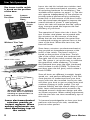
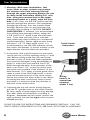
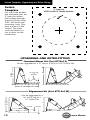
We make
the best boats better!™
LENCO MARINE
Owner’s Manual
Trim Tab Operation
CONGRATULATIONS!
You have just purchased the finest, high performance trim tab
system in the world! Welcome to the future.
Lenco trim tabs make the single most important difference in the
way your boat will ride and perform. Lenco trim tabs will make
your boat ride smoother, drier, faster, increase fuel efficiency
and will increase safety whether on a small skiff or a mega-yacht.
Lenco’s ballscrew design is more reliable, twice as powerful
and features an instant response, which makes them very user
friendly compared to typical hydraulic trim tabs. Lenco trim tabs
are oil free and are environmentally friendly. Our goal is to make
products that simply make boating more enjoyable.
Standard
Mount Kit
Edge Mount Kit
Troll’n Tabs Kit
Racing Tabs Kit
The contents of this manual are subject to change without notice and do not constitute a commitment
on the part of Lenco Marine Inc. Every effort has been made to ensure the accuracy of this document.
However due to ongoing product improvement and revision, Lenco Marine cannot guarantee the accuracy
of printed material after date of publication nor can it accept the responsibility for errors or omissions. Lenco
Marine will update and revise this document as needed. Reproduction or duplication of the manual, or any
part thereof is prohibited without the expressed written permission of Lenco Marine Inc.
All rights reserved. © 2002 Lenco Marine
2
Lenco Marine
Contents
Trim Tabs
Operations . . . . . . . . . . . . . . . . . . . . . . . 4
Safety . . . . . . . . . . . . . . . . . . . . . . . . . . . 5
Special Conditions . . . . . . . . . . . . . . . . . 5
System Parts . . . . . . . . . . . . . . . . . . . . . . 6
Troubleshooting . . . . . . . . . . . . . . . . . . . 6
Additional Information . . . . . . . . . . . . . . 6
Installation Instructions . . . . . . . . . . . . . . 7
Wiring Diagrams . . . . . . . . . . . . . . . . . . . 9
Switch Template . . . . . . . . . . . . . . . . . . 10
Warranty . . . . . . . . . . . . . . . . . . . . . . . 12
Hatch Lifts . . . . . . . . . . . . . . . . . . . . . . . . . . 21
Troll’n Tabs
Operations . . . . . . . . . . . . . . . . . . . . . .
Maneuvering . . . . . . . . . . . . . . . . . . . .
Troubleshooting . . . . . . . . . . . . . . . . . .
System Parts . . . . . . . . . . . . . . . . . . . . .
Installation Instructions . . . . . . . . . . . . .
Warranty . . . . . . . . . . . . . . . . . . . . . . .
14
15
16
18
19
13
Indicator Switch Options . . . . . . . . . . . . . 11
Upgrading and Retro-fitting . . . . . . . . . . . 10
Product Summary . . . . . . . . . . . . . . . . . . . . 22
Owner’s Manual
Trim Tab Operation
The Lenco tactile switch
is based on the position
of the bow.
Lowers
Port Bow
Lowers
Starboard
Bow
Standard
Switch
#124
Without Trim Tabs
With Trim Tabs
When the tabs are lowered,
the water flow is redirected
creating an upward force at
the stern of the boat.
Lenco electromechanical
actuators provide an
instant response. When
making adjustments use
short momentary taps of
the switch.
4
Lenco trim tab kits include two stainless steel
planes, two electromechanical actuators, and
all mounting hardware for installation. ( See
available switch options on page 11.) The trim
tabs operate independently of one another to
provide optimal performance by redirecting
water flow at the transom of the boat. Lenco
trim tabs have been designed to improve the
overall attitude of a boat. If used properly,
Lenco trim tabs will improve the ride, reduce
drag, increase speed and improve the fuel
efficiency of your boat.
The operation of Lenco trim tabs is basic. The
two stainless steel planes are mounted with
the actuators on the transom of the boat.
When the tabs are lowered, the water flow
is redirected creating an upward force at the
stern of the boat. When the stern rises, the
bow will lower.
Since Lenco actuators are electromechanical,
they provide an immediate response at the
touch of the switch. The Lenco switch is
based on the position of the bow. The left
side of the switch controls the starboard tab.
The right side of the switch controls the port
tab. The system is set up this way to minimize
the guesswork while underway. To lower
the starboard bow press the right (starboard)
switch where it reads DOWN. To lower the
port bow press the left (port) switch where it
reads DOWN.
Since all boats are different in weight, length,
speed, etc. and perform differently it will take
some practice to understand how your boat
reacts with trim tabs installed. Lenco trim tabs
will allow your boat to get on plane faster and
continue planing at lower speeds. This will
improve visibility and the overall safety of your
boat. Lenco electromechanical actuators are
designed around a ballscrew design and offer
an instant response. When making adjustments
with the trim tabs use short momentary taps of
the switch.
To become knowledgeable on how your boat
performs with Lenco trim tabs, remember,
practice makes perfect.
Lenco Marine
Trim Tab Operation
SPECIAL CONDITIONS
HEAD SEA
Head Sea — Lower both tabs slightly by pressing BOW
DOWN on both sides this will bring bow down while
maintaining speed. This allows the hull of the boat to
absorb the impact of the waves. This adjustment will
result in a more efficient and smoother ride.
FOLLOWING SEA
Following Sea — Make sure the tabs are fully retracted
by pressing BOW UP on both sides. This will bring
both tabs to a fully retracted position decreasing lift
in the stern and will allow the bow to rise. If tabs are
deployed the bow may dig.
WINDY CHOP
Windy Chop — To raise the windward side of the
boat press BOW UP on that side. If this is not sufficient
press BOW DOWN on the leeward side of the boat.
Do not over trim when attempting this. This will
allow the windward side of the boat to rise and will
minimize spray.
SHALLOW WATER
HOLE SHOT
Shallow Water/Hole Shot — Lower both tabs
completely down by pressing BOW DOWN on both
sides. This provides lift in the stern of the boat and
will keep the bow down. As you throttle up and
speed increases raise tabs by pressing BOW UP on
both sides.
UNEVEN LOAD
Uneven Load- If one side of the boat is higher than
the other while running press BOW DOWN on the
switch on that side. This will lower the tab on the
listing side (low side) to bring the boat level.
PORPOISING
Porpoising — To stop porpoising, press BOW DOWN
on both sides of the switch. The tabs need only to be
deployed slightly to correct this adverse situation.
SAFETY
While the boat is underway do not move one tab up or down significantly,
this may cause listing.
While at higher speeds do not overtrim. This will cause the bow to lower
quickly, resulting in a reduction of speed and may cause the boat to veer.
When in following seas or when running an inlet, the tabs should be fully
retracted. This will allow for optimal performance.
While operating trim tabs use caution. Improper use of trim tabs may cause
accidents and/or injury.
Owner’s Manual
5
Trim Tab System Parts & Trouble Shooting
1
Stainless steel blade with hinge
B -9x12 (dimenisions of tab)
2
Electromechanical actuator
with 25ft lead
101, 101XD, 101XDS
3
Upper mounting bracket
# 119
4
Space saver upper mounting
bracket (optional)
# 117
5
Lower mounting bracket
# 118
6
Retro Kit Bracket
# 116
7
Delrin pin
# 121
8
Standard tactile switch
# 124
9
Indicator switch (optional)
# 123
10
Shim kit (optional)
# 118s
11
1 1\4 inch S.S. Pan head screw
12
7/8 x 1/4 - 20 S.S. screws
13
1/4-20 machine loc nut
TROUBLESHOOTING GUIDE
FOR TRIM TABS
Trim tabs do not work together,
independently, or intermittently.
Solution Sequence:
• Inspect fuse (optional) at fuse panel.
Replace if necessary.
• Verify that all connections at tactile
switch control box or double rocker
switch assembly are tight and in place.
• Make sure that switch assembly has a
solid ground.
• If the actuator cables were spliced
inside the transom, inspect joint for
positive connection.
• After following steps stated above
and the actuators still do not operate
properly — STOP and call the factory
for further assistance at:
(772)288-2662.
6
ADDITIONAL INFORMATION
• Check electrical connections behind
switch and make sure ground wire is
in place.
• The addition of a zinc anode will deter
electrolysis. It is important that the zinc
is in contact with the trim tab blade.
• To discourage any marine growth
on tab or actuator, antifouling paint
can be applied. When applying paint
to the actuator make sure it is fully
retracted. Do not paint the stainless
ram above the area that is exposed
when retracted.
• If tabs malfunction or tabs become
stuck in the down position while
underway remove pin or bolt at the
lower mounting bracket
• To reposition the actuator turn
stainless steel ram counter clock wise
and reattach. You can also resecure
the tab manually by fastening the
lower mounting bracket.
Lenco Marine
Trim Tab Installation Instructions
Warning: The following instructions contain important safety
information and should be followed carefully. Failure to do so may
result in injury and will void warranty.
Please read complete instructions before starting application!
TOOLS AND MATERIALS LIST
electric drill
5/32", 3/32", 3/16", & 3/8" drill bits
4 ft level/straight edge
#2 & #3 phillips screw driver
wire crimper/cutter
7/16" wrench
3m 5200 adhesive caulking
3m silicon marine sealer
1. Begin by first deciding where the trim tab kit
will mount. NOTE: When laying out desired tab
location, hold tab against transom 3/8" up from
bottom of transom in line with hull. Make sure
not to mount inside corner of hinge within 2" of
a strake edge. If this is not possible, move tab so
as to cover strake edge (see Fig.1).
2. Using the 3/16" drill bit, drill hinge holes to a
depth of 1-1/4". When drilling tab and bracket
holes, you may drill through the transom; the
screws will seal the holes when inserted. All
screws and fasteners are stainless steel. Do not
use any other type of metal. It is recommended
to use 3M 5200 adhesive caulking to bed the
hinge and screws. Next, mount the hinge to the
boat using the 1-1/4" S.S. metal screws.
3. With bolts, washer, and nylon locking nuts
provided, fasten lower mounting bracket to
tab. Attach the actuator to the brackets top and
bottom using the delrin pins provided. (When
mounting racing tabs, substitute delrin pin with
5/16 x 1" stainless steel bolt provided). In order
to position upper bracket against transom, you
must lift trim tab so that the trailing edge is
approximately 5/8" above a straight edge held
to hull. This 5/8" measurement is for all tabs that
have a trailing edge 9" off of the transom. If the
trailing edge is 12" off of the transom, lift the
tab so there is 3/4" between the tab and the
straight edge (see Fig. 2). When the tab is at the
appropriate level, use the two outside holes of
the upper bracket as a guide to mark mounting
location. Mount upper bracket where it lays
naturally against the transom to prevent binding
during travel. (Do not adjust the upper bracket
to the right or left, this will cause binding.)
Remove upper bracket from actuator to mark
upper screw hole. Drill three 3/16" holes 1-1/4"
deep.
Owner’s Manual
tape measure
small hammer
2" hole saw
Fig. 1
�� �� �� ��
���� �����
���� �� ����
������ ����
�� �������
��
������
����
Fig. 2
Standard Mount
���
������
������
���
��������
����
����
����
���
��
Edge Mount
���
������
������
���
��������
����
����
���
7
Trim Tab Installation
4. Warning: With some installations, fuel,
water tanks or other systems may prevent
the actuator wire from entering the hull
through the upper mounting bracket. Be sure
to check inside hull before drilling 3/8" wire
hole. Using the centered hole in the upper
mounting bracket as a guide, mark the wire
hole. If all is clear, use the 3/8" drill bit and drill
the hole through the transom. Drill completely
through the transom. Pass the actuator cable
through. Remove slack on wire into hole and
seal with clear caulking or 3M 5200. DO NOT
OVERTIGHTEN. If, however, you are prevented
from drilling hole through bracket, simply drill
a 3/8" hole 4"to 5" above water line and insert
wire. Cover hole and wire with a clamshell
vent sealed with clear caulking for a waterproof
and finished effect. Mount upper bracket using
the three 1-1/4" S.S sheet metal screws. It is
recommended to use 3M 5200 adhesive to bed
the screws and bracket. To attach actuator to the
upper bracket use black delrin pin provided.
5. At the helm, find a good location for the tactile
switch and cut a circular opening using a 2" hole
saw. Before cutting make sure the area inside
the helm is clear of wires and other equipment
that could be damaged. Using the template on
page 10, mark each stud and drill four 5/32"
holes through the helm. If the thickness of the
helm is less than 1-1/4" secure the switch with
the nylon nuts provided. If the thickness of the
helm exceeds 1-1/4" apply a marine grade silicon
sealer to each of the four drilled holes, to each
stud and around the back of the tactile switch.
Secure the switch and allow sealer to dry. When
mounting the black control box, keep in mind
that there is a three-foot lead that attaches to
the back of the tactile switch.
Tactile Switch
Connection
Wiring
harness to
control box
mounted
within 3 feet
6. Following the trim tab switch wiring diagram,
pull the 25' cylinder wires to the switch location.
Be very careful of sharp edges that may damage
the cable. Make all connections according to
diagram. Remember the left switch controls the
right starboard tab and the right switch controls
the left port tab.
PLEASE FOLLOW THE INSTRUCTIONS AND DRAWINGS CAREFULLY. CALL THE
LENCO SERVICE DEPARTMENT AT (772) 288-2662 FOR TECHNICAL ASSISTANCE.
8
Lenco Marine
Trim Tab Wiring 123 & 124
������ ���� ��� ��������� ������ �����������
���� � ��� � �������
���� � ������
������� � ������
�� �
����
�������� �������� ����
���
����
����
�����
���� ���� ���
������������
������ ������
����� ���� ���� ��� �����
���� ���
�������
���
����� ���� ���� ��� �����
����� ���� ���� ����� �����
����� ���� ���� ����� �����
��������� ���� ���
������� ��� ���� ������� �� ������
�� ���� �� �� �� ���� ��
This product must ne installed and wired exactly as shown above. Failure to wire the trim tab indicator
and retractor as shown will cause the cancellation of all warranties by the manufacturer.
�������� ������� ������ ������ �������
���� � ���
�� �
����
�������� �������� ����
���� ���� ���
���
�����
����
� ������� ��� ���� �������
���� ���� ��
� ������ ���� ������� ���� ������
�������� ���� ���� ����
� ���� ��� ���������� ������
���� ��� ��������� �� �����
�����
����
����� ���� ���� ��� �����
����� ���� ���� ��� �����
���� ���
�������
���
����� ���� ���� ����� �����
����� ���� ���� ����� �����
��������� ���� ���
Owner’s Manual
9
Switch Template, Upgrading and Retro-fitting
Switch
Template
2” hole for
#123 & #124 Tactile Switchs
Cut out at the dashed
line and place over the
2” hole you drilled.
Drill straight through
the black circles using
5/32” drill bit for the
mounting bolts (The
bolts are part of the
switch). The inner
circle should be cut
out to allow for the
connection.
UPGRADING AND RETRO-FITTING
Standard Mount Kit (Part #TT9x12)
Can be upgraded to a 12” tab or a 9x12 or 12/12 Troll’n Tab
�� ����� ���
��
��� ����
���
������
������
���
��������
��
���
���
Edgemount Kit (Part #TT12x12E)
Can be upgraded to a
16” or 18” tab or a
12” Troll’n Tab
���
���
������
������
���
��������
�������
���
10
�������
���
���
Lenco Marine
Optional Switchs, Upgrading and Retro-fitting
OPTIONAL SWITCHS
Complete your trim tab system with
the latest switch technology — totally
waterproof, maintenance -free switches
that retract your trim tabs when power
is removed.
All Lenco switches feature:
• Completely waterproof,
maintenance-free
• Self-contained sealed key pad
• Self-contained sealed control box
module
• Fade/smudge proof laser engraved
graphics
• Quick, easy 15 minute installation
• Plug & play switch wiring harness
connector
• Low profile design
• No moving parts
• Solid state electronic components
Switches 124G, 123, 123DR & 123TNT
include:
• Built-in retract feature
returns tabs to a fully retracted
position when power is removed.
Indicator Switches 123, 123DR (Dual
Actuator) & 123TNT (Troll’n Tab)
include:
• 2 High intensity L.E.D. indicator
displays show exactly the position of
your trim tabs at all times.
• Photo Eye
reads ambient light and adjusts the
L.E.D. indicator display intensity for
optimum viewing in direct sun light.
• Backlit key pad graphics for optimum
night viewing.
OPERATION
The operation of the indicator switch
is based on the position of the bow. To
lower the starboard bow, press the right
(starboard) side of the switch where it
reads Down. This will lower the port tab.
To lower the port bow, press the left
(port) side of the switch where it reads
Down. This will lower the starboard tab.
The LED displays on the sides of the
display will show how far that tab has
moved.
When the on/off switch is turned on at
the helm the LED displays on the indicator
switch will show one up arrow on each
side of the switch. This shows that both
tabs are fully retracted. While functioning
the tabs the LED displays will indicate the
position of the tabs by lighting up the
further they are pressed Down. As the
switch is pressed Up the lights will go out.
When power is removed from the switch
the tabs will retract from any position
before powering down.
To lower the
port bow
To lower the
starboard bow
Indicator
Switch
#123
Upgrading and Retro-fitting
Standard Tab to Troll’n Tab
A 9x12 trim tab can be upgraded to Troll’n Tab Kit sizes 9x12 (part #TNT 9x12/24V) or
12x12 (part #TNT 12x12/24V).
Standard Tab blade upgrade
For a larger trim tab blade a 9x12 blade (part# B9x12) can be retro-fitted with a
12x12 blade (part # B12x12).
Edgemount Kit Upgrade
Edgemount Kits require approximately 11” from the top of the upper bracket
to the bottom of the hinge.
Since the placement of the upper bracket is lower than a Standard mount, an
Edgemount can be fitted only with another Edgemount trim tab. (part #’s: B12x9 E,
B12x12 E, B12x18E, Racing Tabs BRT 12x12, BRT 16x12, BRT 18x14)
Edgemount Tab to Troll’n Tab
The only Troll’n Tab kit that will retrofit with any Edgemount trim tab kit is the TNT
12x12/24V (part #TNT 12x12/24V).
Owner’s Manual
11
Trim Tab Warranty
�����
��
�
�
�
�
����
�
����
LENCO TRIM TABS AND
HATCHLIFTS CARRY A
THREE YEAR LIMITED
WARRANTY FROM THE
DATE OF PURCHASE
When possible, please refer to our
trouble-shooting guide on our website,
http://www.lencomarine.com prior to
processing your claim with the Lenco
factory.
1. Call Lenco Marine at 772-288-2662,
and ask for customer service. Give
the technician a brief description of
the product and the problem. Once
the tech determines that the product
is eligible for repair or replacement,
they will issue you an RMA number
(Return Merchandise Authorization).
Claims will not be processed
without an RMA number.
2. Return product and paperwork to
Lenco Marine with the following
information: (name, telephone
number, description of problem,
proof of purchase to verify
warranty). Proof of purchase and
warranty info can consist of the
following:
A. Original Lenco Marine invoice, or
copy.
B. Lenco Dealer invoice.
C. Factory installed bill of sale
3. Mark the outside of the package
with the RMA number and return
it to Lenco Marine customer
service department at 4700 SE
Municipal Court, Stuart, Fl 34997
for processing. Once received,
our customer service department
will make every effort to process
your return quickly. Should time
restraints prohibit you from sending
in the merchandise first, or you
need an immediate replacement,
you will be required to secure the
replacement part with a credit card
prior to shipment (Visa, MasterCard,
12
American Express, Discover). Lenco
marine ships all warranty items
UPS ground. Costs for upgrades in
shipping will be the responsibility
of the customer. Lenco Marine
warranties all trim tabs and hatch
lifts for a period of three years from
the date of purchase. If any part
of a Lenco trim tab or hatch lift
fails due to manufacturing defects
or workmanship within a period
of three years from the date of
purchase, Lenco Marine will repair or
replace the part(s) without charge at
our discretion. No haul out, labor, or
miscellaneous charges are covered
under this warranty.
Troll’nTab customers please see separate
warranty policy. The foregoing is in
lieu of any and all other warranties,
expressed or implied, including any
warranty of merchantability or fitness
for a particular purpose. There are no
other warranties which extend beyond
that set forth above. Lenco Marine
reserves the right to void any warranty
claim if the part is opened or repair was
attempted, without prior authorization
from Lenco Marine.
Lenco Marine Inc.
Phone: 772-288-2662
Fax: 772-288-2566
www.lencomarine.com
4700 SE Municipal Court
Stuart, Fl 34997
Lenco Marine
Troll’n Tab Warranty
�����
��
�
�
�
�
����
�
����
LENCO TROLL’N TABS
CARRY A TWO YEAR
LIMITED WARRANTY
FROM THE DATE OF
PURCHASE
When possible, please refer to our
trouble-shooting guide on our website,
http://www.lencomarine.com prior to
processing your claim with the Lenco
factory.
1. Call Lenco Marine at 772-288-2662,
and ask for customer service. Give
the technician a brief description
of the product and the problem.
Once the tech determines that that
the product is eligible for repair or
replacement, they will issue you an
RMA number (Return Merchandise
Authorization).
Claims will not be processed
without an RMA number.
2. Return product and paperwork to
Lenco Marine with the following
information: (name, telephone
number, description of problem,
proof of purchase to verify
warranty). Proof of purchase and
warranty info can consist of the
following:
A. Original Lenco Marine invoice, or
copy.
B. Lenco Dealer invoice.
C. Factory installed bill of sale
3. Mark the outside of the package
with the RMA number and return
it to Lenco Marine customer
service department at 4700 SE
Municipal Court, Stuart, Fl 34997
for processing. Once received,
our customer service department
will make every effort to process
your return quickly. Should time
restraints prohibit you from sending
in the merchandise first, or you
need an immediate replacement,
you will be required to secure the
replacement part with a credit card
prior to shipment (Visa, MasterCard,
Owner’s Manual
American Express, Discover). Lenco
Marine ships all warranty items
UPS ground. Costs for upgrades in
shipping will be the responsibility
of the customer. Lenco Marine
warranties all Troll’n Tabs for a
period of two years from the date
of purchase. If any part of a Lenco
Troll’n Tab fails due to manufacturing
defects or workmanship within a
period of two years from the date of
purchase, Lenco Marine will repair or
replace the part(s) without charge at
our discretion. No haul out, labor, or
miscellaneous charges are covered
under this warranty.
*Trim Tab and Hatch lift customers
please see separate warranty policy.
The foregoing is in lieu of any and
all other warranties, expressed or
implied, including any warranty
of merchantability or fitness for a
particular purpose. There are no other
warranties which extend beyond that
set forth above. Lenco Marine reserves
the right to void any warranty claim
if the part is opened or repair was
attempted, without prior authorization
from Lenco Marine.
Lenco Marine Inc.
Phone: 772-288-2662
Fax: 772-288-2566
www.lencomarine.com
4700 SE Municipal Court
Stuart, Fl 34997
13
Troll’n Motor Operation
Guidelines for trim tab operation located on page two.
OPERATION OF TROLLING
MOTORS
To position motors correctly for trolling press Bow
Down for more than five seconds on the trim tab
switch. This will fully extend both cylinders so the
motors are parallel with the plane of the hull.
To begin use with the trolling motors turn control
box ON by flipping the single toggle switch. When
the system is activated, you may control the motors
with the hand control that plugs into the control
box. The hand control has three toggle switches.
One switch marked HIGH or LOW, has positions
for trolling speeds and neutral. For higher speed
press switch to the right side of the hand control
that reads HIGH. For lower speed press switch to
the left side of the hand control that reads LOW.
The neutral position between the HIGH and
LOW will disengage the trolling motors.
The neutral
position
between the
HIGH and LOW
will disengage
the trolling
motors.
There are two other switches on the hand control
that control the forward or reverse direction of
thrust. These switches are located side by side on
the hand control. For forward on the port trolling
motor press the left switch up where it indicates
FORWARD. For reverse on the port trolling motor,
press the left switch down where it indicates
REVERSE. For forward on the starboard trolling
motor press the left switch up where it indicates
FORWARD. For reverse on the starboard trolling
motor, press the left switch down where it indicates
REVERSE. Note these switches will not
engage trolling motors when thrust switch
is between HIGH and LOW.
SPECIAL RECOMMENDATIONS FOR TROLL’N TABS
• After use make sure thrust switch on the hand control is set in the OFF
position between the HIGH and LOW settings
• Make sure that the control box is switched to OFF after use
• To prolong the life of the control box do not change direction when motors
are engaged in either direction
• To change direction of motors make sure to bring the thrust switch to a
neutral position and then change direction
14
Lenco Marine
Troll’n Motor Maneuvering
MANEUVERING
Since the trolling motors are stationary and do not
pivot, it is important to use both trolling motors to
maneuver.
To move the boat forward press both directional
switches up towards the FORWARD setting. This
will set only the direction for both of the trolling
motors. To engage the trolling motors press the
other switch to either the right or left. For HIGH
press it to the right. For LOW press it to the left.
To move the boat in reverse press both directional
switches down towards the REVERSE setting. This
will set only the direction for both of the trolling
motors. To engage the trolling motors press the
other switch to either the right or left. For HIGH
press it to the right. For LOW press it to the left.
To turn the boat there are two options. These
options depend on how hard of a turn is desired.
Remember, when the speed setting is switched to
HIGH the boat will react faster to your commands.
Move
Boat
Forward
Move
Boat
Reverse
Turn Boat
To turn the boat to the right press the directional
switch on the left side of the hand control up to
where it reads FORWARD. To engage the port
trolling motor press the switch to the left for LOW
or to the right for HIGH. This will result in a wide
turn to the right. To make a hard turn to the right
engage the starboard trolling motor in reverse. This
may be accomplished by pressing the right switch
down to where it reads REVERSE.
Turn
Boat
Hard
Right
To turn the boat to the left press the directional
switch on the right side of the hand control up to
where it reads FORWARD. To engage the starboard
trolling motor press the switch to the left for LOW
or to the right for HIGH. This will result in a wide
turn to the left. To make a hard turn to the left
engage the port trolling motor in reverse. This may
be accomplished by pressing the left switch down
to where it reads REVERSE.
Turn Boat
Hard Left
(For wide turn
do not press
reverse)
Note these switches will not engage
trolling motors when thrust switch is
in neutral—between HIGH and LOW.
Owner’s Manual
15
Troll’n Motor Troubleshooting Guide
1. Trim Tab cylinders work but
trolling motors do not.
Solution Sequence:
1.1 Check system On/Off switch located
on top of the main control box.
Insure that it is in the ON position.
1.2. Check the hand control connector,
located on the side of the main
control box. Verify that it is fully
inserted and corrosion free.
1.3 Inspect the fuses connected to the
main control box. If a fuse is blown,
the motors will not work. Replace
fuse if necessary.
1.4 Verify that all connections at the
main control box terminal strip are
accurate and tight, as per Troll’n Tab
wiring diagram.
1.5 Assess the system batteries state of
charge. Set both motors on FWD
and on HIGH with the Hand Control,
check the voltage of each battery
independently. Voltage
should read 11.5 volts minimum.
Charge batteries if necessary.
2. Motors will run on Low
speed, but not on High.
Solution Sequence:
2.1 Inspect connections at batteries,
verify that the 24-volt jumper has
been installed according to Troll’n
Tab wiring diagram.
2.2 Inspect the fuses connected at the
terminal strip of the main control
box.
2.3 Inspect the hand control unit for
a damaged HIGH/LOW selector
switch. The switch should positively
engage and maintain the various
switched positions.
16
2.4 Check main control box terminal strip
for accurate and tight connections
according to the Troll ’n Tab wiring
diagram.
3. One motor works and the
other does not.
Solution Sequence:
3.1 Verify that the Hand Control
connector on the side of the Main
Control box is fully inserted and
corrosion free.
3.2 Assess the system batteries state
of charge. Often times the battery
voltage is just low enough that one
motor will operate while the other
just slightly kicks over at start up.
The one motor that does run, only
does so because it is the efficient of
the two, therefore all excess voltage
that remains gets diverted to that
motor. To verify that this is the case
turn the running motor off and
the other motor on. If it runs this
time the problem lies in the state
of charge in the batteries. Charge
batteries if necessary.
3.3 Verify that all connections at the
Main Control Box terminal strip are
tight and accurate as per Troll’n
Tab wiring diagram. If steps 3.1,
3.2, and 3.3 have been completed
and one motor still does not
operate, proceed to steps below to
determine if problem lies with the
Motor, Main Control Box, or the
Hand Control.
3.4 Motor Test: Connect motor leads
to a 12 Volt power supply to verify
if the motor operates normally,
isolated from the system. If not,
contact our warranty and service
department for repair at
772-288-2662.
Lenco Marine
Troll’n Motor Troubleshooting Guide
3.4 Main control box test: At the main
control box disconnect the two Red
motor leads and two Green motor
leads from the terminal strip. Next
reconnect the Red motor leads in
the location the Green motor leads
were removed from. Reconnect the
Green motor leads to the location
the Red motor leads were removed
from. If you have already completed
troubleshooting steps 3.1 to 3.4
and one motor still does not work
then STOP…, and contact our
warranty and service department
for further instructions at
772-288-2662.
3.5 Hand Control Test: Visually examine
the switches on the Hand Control
unit for damage. Operate all
switches through their normal
switching positions, the switches
should positively engage and
maintain the various switched
positions. If the Hand Control is
damaged or defective contact the
factory for repair or replacement at
772-288-2662
4. Batteries have been
completely discharged,
however, when onboard
charger was activated it
indicated a green light,
representing a fully charged
battery.
Solution Sequence:
to restore the batteries from such
a level of depletion. The solution
to this dilemma is to first unplug
the onboard charger, and attach
a 10 amp household charger for
20 -30 minutes. This will bring the
state of charge up to a level that
the onboard unit can effectively
take over. After 20-30 minutes,
disconnect the household charger
and allow the onboard unit to
complete the charging process.
5. Charger is connected but no
lights appear on unit.
Solution Sequence:
5.1 Check the 110 volt AC power
supply from its source through
all connecting points up to the
charger by using a meter or lamp
to confirm that current is being
delivered to the charger. *If 110
volt AC power supply is connected
to a safety GFCI outlet, be sure that
the outlet is in the reset position
and that current is present.
*Note always verify that the charger
lights are on when attempting to charge
batteries.
If you are still experiencing
other problems or difficulties
not described in this guide
please contact our service
department at 772-288-2662.
4.1 The battery or batteries have been
discharged below 5 volts. When the
batteries have been discharged to
such extent, the onboard charger
can no longer bring the batteries
up. Simply because the onboard
charger has been designed to be
completely waterproof, therefore
the unit is totally sealed and will
generate too much heat attempting
Owner’s Manual
17
Troll’n Motor System Parts
1
2
3
4
5
6
7
8
9
10
11
12
13
14
15
16
17
18
19
20
Stainless steel blade with hinge
Trolling motor bracket
Motorguide 24v-82lbs
Motorguide Machette II (3 blade prop)
Electromechanical actuator with 25ft lead
Upper mounting bracket
Lower mounting bracket
Delrin pin
118S (optional)
Standard Tactile Switch
TNT Indicator Switch (optional)
TNT control box with terminal
TNT hand control with 30ft lead
Nylon washers
Nylon hanger
1-1/4 inch s.S. Pan head screw
7/8x1/4-20 machine screw
1/4-20 machine loc nut
5/16 machine loc nut
5/16x2-1/4 machine bolt
# BTNT-9X12 (dimensions of tab)
Bracket
# MG24V-82
# Prop
# 102xd
# 119
# 118
# 121
# Shim kit
#124
#123TNT
# TNTCB
# TNTHC
������� ���� ������ �������
������
�����
����� ����
����� ����
�����
�����
�� ����
������
�����
��������
���
�����
��� ����
��
����� ����
�
��� ����
��
����� ����
�
�� ����
���
�����������
�����
�����
����� ����
�����
������
����
��� ����
���
����� ����
��� ����
���
����
�������
������� ���
18
Lenco Marine
Troll’n Tab Installation Instructions
WARNING: The following
instructions contain important
safety information and should be
followed carefully.
Failure to do so may result in
injury and will void warranty.
Please Read Complete Instructions
Before Starting Application!
Tools And Materials List
• Electric Drill
• Wire Crimper/Cutter
• 3/32", 3/16", & 3/8" Drill Bits
• Tape Measure
• 7/16" Wrench
• Small Hammer
• 4 Ft Level/Straight Edge
• 3m 5200 Adhesive Caulking
• 2 3/8" Hole Saw
• #2 & #3 Phillips Screw Driver
1. Begin by first deciding where the
trim tab kit will mount. NOTE: When
laying out desired tab location, hold
tab against transom 3/8" up from
bottom of transom in line with hull.
Make sure not to mount inside corner
of hinge within 2" of a strake edge. If
this is not possible, move tab so as to
cover strake edge (see Fig.1).
must lift trim tab so that the trailing
edge is approximately 5/8" above a
straight edge held to hull. This 5/8"
measurement is for all tabs that have
a trailing edge 9" off of the transom.
If the trailing edge is 12" off of the
transom, lift the tab so there is 3/4"
between the tab and the straight
edge (see Fig. 2). When the tab is
at the appropriate level, use the two
outside holes of the upper bracket as
a guide to mark mounting location.
Mount upper bracket where it lays
naturally against the transom to
prevent binding during travel. (Do
not adjust the upper bracket to the
right or left, this will cause binding.)
Remove upper bracket from actuator
to mark upper screw hole. Drill three
3/16" holes 1-1/4" deep.
Fig. 1
Owner’s Manual
���� �� ����
������ ����
�� �������
��
������
����
2. Using the 3/16" drill bit, drill hinge
holes to a depth of 1-1/4". When
drilling tab and bracket holes, you
may drill through the transom; the
screws will seal the holes when
inserted. All screws and fasteners are
stainless steel. Do not use any other
type of metal. It is recommended
to use 3M 5200 adhesive caulking
to bed the hinge and screws. Next,
mount the hinge to the boat using
the 1-1/4" S.S. metal screws.
3. With bolts, washer, and nylon locking
nuts provided, fasten lower mounting
bracket to tab. Attach the actuator to
the brackets top and bottom using
the delrin pins provided. (When
mounting racing tabs, substitute
delrin pin with 5/16 x 1" stainless steel
bolt provided). In order to position
upper bracket against transom, you
�� �� �� ��
���� �����
Fig. 2
����
����
4. Warning: With some installations,
fuel, water tanks or other systems
may prevent the actuator wire from
entering the hull through the upper
mounting bracket. Be sure to check
inside hull before drilling 3/8" wire
hole. Using the centered hole in
(cont.)
19
Troll’n Tab Installation Instructions
the upper mounting bracket as a
guide, mark the wire hole. If all is
clear, use the 3/8" drill bit and drill
the hole through the transom. Drill
completely through the transom. Pass
the actuator cable through. Remove
slack on wire into hole and seal with
clear caulking or 3M 5200. DO NOT
OVERTIGHTEN. If, however, you are
prevented from drilling hole through
bracket, simply drill a 3/8" hole 4"to
5" above water line and insert wire.
Cover hole and wire with a clamshell
vent sealed with clear caulking for a
waterproof and finished effect. Mount
upper bracket using the three 1-1/4" S.S
sheet metal screws. It is recommended
to use 3M 5200 adhesive to bed the
screws and bracket. To attach actuator
to the upper bracket use black delrin pin
provided.
5. At the helm, find a good location for
the tactile switch and cut a circular
opening using a 2" hole saw. Before
cutting make sure the area inside
the helm is clear of wires and other
equipment that could be damaged.
Using the template on page 10, mark
each stud and drill four 5/32" holes
through the helm. If the thickness of
the helm is less than 1-1/4" secure the
switch with the nylon nuts provided.
If the thickness of the helm exceeds
1-1/4" apply a marine grade silicon
sealer to each of the four drilled
holes, to each stud and around the
back of the tactile switch. Secure the
switch and allow sealer to dry. When
mounting the black control box, keep
in mind that there is a three-foot lead
that attaches to the back of the tactile
switch.
6. Following the trim tab switch wiring
diagram, pull the 25" cylinder wires
to the switch location. Be very careful
of sharp edges that may damage the
cable. Hook up according to diagram.
Remember the left switch controls
the right starboard tab and the right
switch controls the left port tab.
20
7) With the trim tabs operating as
described, you are now ready to wire
the trolling motors, batteries and
control box. First, select a place to
mount the control box, i.e., in a rear
rigging hatch, still allowing access to
on/off switch. As an option, control
box may be mounted in the console;
however, motor wires may need to be
extended. If so, use a #10 wire and be
sure to heat shrink all connections for
a watertight seal.
8) Next, run trolling motor leads to
the control box. You may run leads
through the splash well drains on
either side of the engine, then into
the rigging hatch with the engine
control/steering cables. Attach wires
to terminal block according to wiring
diagram provided. If splash-well
drains are not an option, you may
need to drill a 1/2" hole above water
line and insert wire. Cover hole and
wire with a clamshell vent sealed with
caulking for a waterproof and finished
effect.
9) When wiring from batteries to the
control box, use a minimum of #6
AWG for all three conductors. Also,
note that the control box is fused on
both 12V and 24V power leads. Fuses
are 60 AMP maxi fuses. WARNING:
Use of fuses larger than 60 AMP could
result in damage to system and will
void warranty. For replacement fuses,
call your local auto parts retailer or
order them from Lenco Marine, Inc.
10) *Special Application*
In the event of a recessed pocket
application, use of shims behind the
upper bracket may be necessary to
prevent actuator binding during
extension. You can adjust the
actuator in the lower channel holes
to obtain the 5/8" up dimension.
Please follow the instructions and
drawings carefully. For technical
assistance call the Lenco Service
Department at: (772)288-2662
Lenco Marine
Hatch Lifts
LENCO ELECTRIC HATCH LIFTS
Lenco hatch lifts are easy to install because they
install with a single power cable. They draw an
average of five amps of power and deliver over 500
pounds of push or pull for heavy engine covers,
decks, large hatches and electric consoles.
Due to the many different variables involved with
the numerous applications for Lenco hatch lifts,
installation is never the same. Here are some
general guidelines that can be of assistance:
S = Short, all part numbers ending in S have
the same stroke but in a 4” shorter length.
• The hatch lift is most powerful when it is installed Part
Number
vertically at 90 degrees
• Lifting capabilities decrease the closer the upper
HL- 400
or lower mount is located to the hinge
HL-800S
• The further from a vertical position the less lifting
HL-800
capability. When retracted, DO NOT position hatch HL-1200S
HL-1200
lift at an angle less than 30 degrees
HL-1600S
• Dual hatch lift systems are recommended for
HL-1600
hatches over 500 pounds
HL-2000S
• Lenco hatch lifts are designed around a ball screw HL-2000
that spins freely when hatch is fully open or closed HL-2400S
HL-2400
• For installation, it is important that the hatch lift
is able to disengage itself at the fully retracted
Lower
position. Failure to make accurate measure could
cause damage to hatch lift or the hatch itself
Hatch
• Lenco hatch lifts are fully submersible and
will not drift.
• Lenco hatch lifts are offered in both 12 and 24 volts
L. O. A. Approx. L. O. A.
Retracted Stroke Extended
15”
21”
25”
25”
29”
29”
33”
33”
37”
37”
41”
4”
8”
8”
12”
12”
16”
16”
20”
20”
24”
24”
19”
29”
33”
37”
41”
45”
53”
53”
57”
61”
65”
OPERATION
The function of the Lenco hatch lift system is simple.
Since the hatch lift is based around a ballscrew it is
able to push or pull a heavy load and remain at a
constant position. To raise a load extend the hatch
lift by pressing on the upper part of the switch. To
lower a load, retract the hatch lift by pressing the
lower part of the switch.
Raise Hatch
It case of power failure Lenco hatch lifts are supplied
with two clevis pins at the mounting brackets. To pull
this pin out while the hatch is closed you must rig it
to a point outside of the hatch.
SYSTEM PARTS
1
Hatchlift
(electro machanical actuator)
2
3
4
5
Mounting Brackets
Clevis Pins
Single Rocker Switch
Slide Bracket
Owner’s Manual
#’s HL-400, HL-800, HL-800s, HL-1200,
HL-1200s, HL-1600, HL-1600s,
HL-2000, HL-2000s, HL-2400, HL-2400s
# 119
# 121SS
# 125 (Optional)
#HLSB (Optional)
21
Kit Overview
Standard Trim Tab Kits
• Standard Trim Tab Kits include: (2) 101 actuators, (2) 12 gauge S.S. trim tabs,
and all mounting hardware. See switch selections on page 11 for available
options.
• Available in Standard Mount and Edge Mount (space saver mount)
• Sizes range from 9” x 9” to 12” x 50” (measurements taken L x W)
TT9x12
TT12x9 E
TT12x12 E
Troll’n Tab Kits
• Troll’n Tab Kits include: (2) 102 XD actuators, (2) 12 gauge S.S. electro polished
tabs, (2) Motor guide—great with 82 pound thrust trolling motors,
(1) trolling tab control box, (1) trolling tab hand control and all mounting
hardware. See switch selections on page 11 for available options.
• Available in sizes: TNT 9x9/24V, TNT 9x12/24V, TNT 12x12/24V (Edgemount
compatible)
TNT12x12
TNT9x12
Complete your trim tab system with one of Lenco’s waterproof tactile switches.
See optional switch selections on page 11 for complete features.
Standard Switch
124 &
124G (w/Retractor)
22
Indicator Switch
w/Retractor
123
123DR (Dual Actuators)
123TNT (Troll’n Tabs)
Lenco Marine
Kit Overview
Racing Tab Kits
Standard, Heavy Duty, Extreme Duty
RT Standard
• Standard Racing Tab Kit includes: (2) 101 actuators, (2) 12 gauge S.S. black
powder coated trim tabs, and all mounting hardware
• Available in sizes: RT 9x12, RT 12x9, RT 12x12, RT 16x12 and RT 18x14
RT18 x 14 HD
• Heavy Duty Racing Tab Kit includes: (2) 101 XD actuators, (2) 12 gauge S.S. black
powder coated trim tabs w/transom back plates
• Available in sizes: RT 12x12 HD • RT 16x12 HD, RT 18x14 HD.
RT19x14 XD
• Extreme Duty Racing Tab Kit includes: (2) 101 XD actuators (RT 17x12XD),
(4) 101 XD actuators (RT 19x14 XD), (2) 10 gauge S.S. black powder coated trim
tabs w/transom back plates and super duty hinge w/3/8” hinge rod
• Available in sizes: RT 17x12 XD, RT 19x14 XD
Swiches: see selections on page 11 for available options.
RT
16x12
RT
16x12
HD
RT
19x14
XD
The Lenco Troll’n Tabs
$100 Retrofit Rebate
A $100 factory rebate will be paid on the purchase of a new Lenco Troll’n Tab Kit to
retrofit existing Lenco trim tabs. Subject to the following applicable proofs of purchase:
1) a bill of sale showing hull I.D. # on the boat which came with Lenco trim tabs
installed. 2) original proof of purchase of a Lenco Trim Tab Kit. 3) The proof of purchase
of the new Lenco Troll’n Tab Kit along with the last page of the owners manual with
the Lenco logo sticker. Send all to the Lenco Marine. Other terms and conditions may
apply. Call a Lenco representative to review before redemption.
When you purchase a
Lenco Troll’n Tab Kit, a Lenco
Marine TNT logo sticker will be
in this oval space. This page
with it’s sticker is one item
needed for proof
of purchase.
Owner’s Manual
23
We make
the best boats better!™
Proudly made in the U.S.A.
Lenco Marine Inc.
4700 Municipal Court • Stuart, Florida 34997
772-288-2662 • 772-288-2566 fax
www.lencomarine.com