1
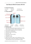
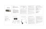
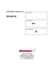
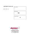
Mounting Instructions
for Navigation Lights
aqua signal 40 / 41 / 42 / 50
-1-
aqua signal 40 / 41 / 42 / 50
Mounting Instructions
for Navigation Lights
of type AQUA SIGNAL 40 / 41 / 42 / 50
These navigation lights comply with the national and
international regulations regarding minimum range of visibility,
luminous intensity of horizontal and vertical sectors, and colour
specifications for vessels of 20 metres and more in length
(Regulations for Preventing Collisions at Sea). Lights marked
¥ D in addition to the DHI resp. BSH marking may be utilized on
European inland waterways.
However, their correct function will only be guaranteed and in
conformance with the regulations if some important points are
considered regarding mounting and maintenance. It is therefore
essential to study the following pages attentively.
Important:
The upper lens compartment of double lens lights is always to
be used within the main lighting system whilst the lower one
belongs to the stand-by system.
Regulations
For all ships the rules set forth in Annex 1 to the International
Regulations for Preventing Collisions at Sea - Positioning and
Technical Details of Lights and Signalling Shapes - must be
adhered to. The technical data regarding horizontal and vertical
positioning and spacing of the navigation and signalling lights
laid down in these mounting instructions do apply to all ships
irrespective of their flag.
A = horizontal plane
CWL = construction waterline
Keel line
Lantern screen
Arrow-marking
Mounting of navigation lights in general*
The lights must be positioned in and above keel line resp.
parallel with it. Their horizontal plane (A) must be parallel with
the construction water line (CWL).
Their light must not be obstructed by parts of the vessel or
objects or persons aboard within a vertical sector of ± 10° and a
horizontal sector corresponding to the one of the lights. Their
relative positions to the vessel are not to be changed while in
operation.
The vertical distance (C) must be minimum 4,5 metres
respectively sufficient to allow recognizing the after masthead
light over and separate from the forward light under all
conditions of trim at a distance of 1000 metres.
These lights are to be operated exclusively with special
approved bulbs. These special bulbs from AQUA SIGNAL are
labeled as follows:
10W ZP D 1301/1303 resp. 25W ZP D1302/1304
* Deviating from the anti collision regulations the forward
masthead light needs be fitted only 5 metres above the hull
and the after masthead light just 3 metres higher if the
vessel is designed and registered for operation on
European inland waterways until the border of high seas
navigation.
-2-
aqua signal 40 / 41 / 42 / 50
Mounting Instructions
MOUNTING INSTRUCTIONS IN GENERAL
.
The lights must be positioned in or parallel to the keel line. Their
horizontal plane (A) must be parallel with the construction water
line (CWL). Their light must not be obstructed by any parts of
the vessel or objects or persons. Their relative positions to the
vessel are not to be changed while in operation.
An upside down mounting is not permissible.
Important note for port and starboard lights
In case screens are used for the sidelights the front screen has to
be removed since it is not necessary and is obstructing the light
output in right ahead direction.
DESCRIPTIONS
SIDELIGHTS SSb + SBb 40/41/42/50
¥ Sidelights -STRONG- red/green SSb + SBb 50
angle 112,5°
visibility 2 nm
BICOLOR SIDELIGHTS TD 40/41/50
¥ Bicolor sidelights -STRONG- red/green TD 50
angle 112,5° red and 112,5° green
visibility 2 nm
TRICOLOR LIGHTS FOR SAILING BOATS
TDH 40, TDH 40 “quicfits”
angle 112,5° red, 112,5° green, 135° white
visibility 2 nm min. for all sectors
COMB. TRICOLOR/ANCHOR LIGHT
TDH / SW 40, TDH / SW “quicfits” FOR SAILING VESSELS
angles:
tricolor 112,5° red, 112,5° green, 135° white
anchor 360° white
visibility 2 nm min.
Regulations for navigation lights Types TDH and TDH/SW40
with and without “quicfits”
The regulations are permitting to use these lights only on sailing
boats <20m.
While under engine these lights are not permitted.
MASTHEAD LIGHT T40/41/50
angle 225°
visibility 3 nm
+
COMB. MASTHEAD/ANCHOR LIGHT T/SW 40
angles:
masthead 225°, visibility 3 nm
signalling 360°, visibility 2 nm
STERN LIGHT H40/41/42/50 +
HGe 40 (stern yellow, towing)
angle 135°
visibility 2 nm
SIGNALLING LIGHTS SW, SR, SG, SGE 40/50
angle 360°, visibility min. 2 nm
These lights are available for pedestal mount and for hoisting
-3-
aqua signal 40 / 41 / 42 / 50
The following lights are exclusively for navigation on
European inland waterways ¥ D
Blind plug
Masthead Light -white/STRONG- TW 50
Signalling light blue-ORDINARY SB 40
Signalling light FLASHING -white-STRONG- SW40
The signalling flashing light has to be equipped with an
approved electronic flasher. The light and the electronic flasher
have to be mounted separately. (Please refer to instructions of
electronic flasher.)
Clamp
washer
Bottom
Cable entry
“YELLOW HORN SIGNAL” with Signalling signal light
YELLOW-STRONG SGe40
Pin connections:
3 Tricolour light
1 Strobe light
2 Anchor light
Combined WHITE/YELLOW (flash/horn) SIGNAL LIGHT
Yellow-STRONG / flash-white-STRONG SGe/SW40
The signalling flashing light has to be equipped with an
approved electronic flasher. The light and the electronic flasher
have to be mounted separately. (Please refer to instructions of
electronic flasher.)
Right ahead
direction
Electronic flasher BG 50 G
The flasher is designed to operate with a supply voltage of 830V DC. Only the control lamp has to be selected according to
the main supply voltage on board.
Technical details:
Charge: max. 35W
Voltage: 8-30V, Frequency: 60 fl./min.
Fuse: 2A delay action fuse, Bright-phase: 50%
Electrical connection by use of terminal
Pin connections are identical with all types. Non-available lantern
functions remain unused
-4-
aqua signal 40 / 41 / 42 / 50
MOUNTING
Locking screw
Silicon
Sidelights Series 40 + 50
The enclosed bracket has to be fitted with 2 screws. Please pay
attention to the right ahead direction. The light is hooked on the
bracket. To obtain a vibration safe holding turn the locking device
at the rear of the light to one side.
Sidelights Series 41
Use backplate to mark hole alignment for drilling. Fix backplate
with 2 screws dia. max. 4 mm horizontally or vertically. Place
housing on the backplate and fasten it by tightening the screw at
the bottom.
Sidelights Series 42
Use the attached template to mark mounting hole. A specialist
should cut the mounting hole. After having fitted the supply cable
to the backwall insert the unit in the mounting hole. Use some
silicon or equivalent to make it tight (remove redundant silicon in
order to attach the housing properly) .
When mounting the unit, pay attention that the air-circulation
openings at the backwall are not covered. Under extreme
operation conditions the center spot of the backwall could reach
137°C. . Fix the backwall with four screws dia. 4 mm. Fit the bulb
. Insert the lens into the backwall. Pull the long screw of the
housing back. Hook the housing in the hooks on the top side of the
backwall, close the lantern and then push the long screw back in
and fix it. The long screw has always to be pulled back when the
housing should be removed or put back into position.
Wall
Rear
Rear
Attention
Hot Spot max.
169°F / 137°C
Keep away inflammable
Materials
Traction relief
Signalling lights, tricolor lights for sailing boats, comb.
tricolor/anchor lights, comb. masthead/anchor lights and
special navigation lights for inland waterways
Series 40
Loosen locking ring. (Only valid for comb. lights) Turn the optic
anti-clockwise. Arrange electrical connection as described in the
chapter ‘electrical installation’. To simplify mounting use base to
mark positions of drilling holes. Pay attention to right ahead
direction when mounting.
To insert bulb
Bulb holder
Tricolor “quicfits”, comb. tricolor/anchor “quicfits”
Series 40
Remove light from “quicfits” base: New model after loosening the
lower locking ring. Old model by compressing the two snap pins.
Arrange electrical connection as described in the chapter ‚electrical
installation‘. To simplify mounting use base to mark positions of
drilling holes. Pay attention to right ahead direction when
mounting. Fix the “quicfits” base with 3 screws dia. 5mm. The
“quicfits” system allows quick removal of the light i.e. to prevent
theft or damage when mast is down. The base remaining on the
mast can be covered with the supplied cap.
Bulb socket
Signalling lights for hoisting
Series 40/50
Unscrew cap nut and remove electrical insert with bulb. A correct
installation of the socket and a watertight closure of the cable
gland are only given when the cable is isolated and connected as
per illustration . For installation remove the socket from the insert
by unscrewing the two screws and when fastening the socket
again pay attention to the leading at the socket, which ensures the
correct position of the bulb.
Push and turn
Signalling lights for pedestal mount
Series 50
To simplify mounting use base to mark position of drilling holes. Fix
the base with 3 screws dia. 5mm. Insert the cable through the hole
in the base and arrange electrical connection according to the
instruction. Place light housing on the base and fasten the cap nut.
-5-
aqua signal 40 / 41 / 42 / 50
ELECTRICAL INSTALLATION
MAINTENANCE
Series 40 + 50 sidelights and Signalling light for hoisting
Loosen cap nut and take electrical insert out.
Important: A correct installation of the socket and a watertight
closure of the cable gland is only given when the cable is isolated and
connected as per illustration . Use round cable of about 7-9mm dia.
with adequate cross-section. For installation remove the socket from
the insert by unscrewing the two screws and when fastening the
socket again pay attention to the leading at the socket, which ensure
the correct position of the bulb.
Navigation lights are not watertight (IP55 and IP56) due to the fact
that air pressure variation caused by the operation temperature
changes of the bulb have to be compensated. For this
compensation the lights are equipped with a ventilation system
through which humidity can escape as well. The ventilation system
must not be plugged by grease, dirt or other materials.
The light should be cleaned if necessary with clear water or
eventually with a cleanser suitable for acrylic glass not containing
any abrasives or solvents.
The bulb should be taken out of the socket on a yearly basis.
Socket and bulb contacts should be cleaned and a drop of contact
oil should be applied prior to inserting the bulb again.
Series 41 sidelights
Open the light by loosening the locking screw at the bottom.
Dismantle cable and insert it through the backplate. Attach 6,3mm
spade connectors to the two wires, push them on the contacts and
fasten the cable clamp.
ATTENTION:
Series 42 sidelights
For installation use 2-core cable with adequate cross-section. Protect
dismantled wires with supplied silicon tubes. Attach 6,3mm spade
connectors and push them on the contacts in the rear of the light.
Secure cable by use of the cable clamp.
Solvents can destroy the optic of a navigation light. We
recommend to remove the light prior to executing paint jobs. The
housing of the light should never be painted for photometric
reasons. The lenses in particular but also other plastic components
may not be touched with paint.
Series 40 Signalling lights, tricolor lights, comb. tricolor/anchor
For installation only use cables of 7-9mm with adequate crosssection. Pull the cable through the bottom of the base. Dismantle
about 60mm of the cable according to ill. Feed cable through cable
entrée and cable clamp parts. Arrange electrical connection and
fasten cable clamp with two screws. The installation should be done
according to this instruction in order to ensure a watertight closure of
the cable gland. Pay attention to ill. for installation of TDH/SW40.
Electrical connection from the side: If cable cannot be pulled in from
underneath remove blind-plug at the side and insert cable gland PGset (order no.: 83514002). With type SGe/SW40 you need 2 PG-sets.
Plug the unused hole in the bottom.
Series 40 tricolor “quicfits”, comb. tricolor/anchor “quicfits”
The electrical connection of these lights is only made in the “quicfits”
base. Use round cable of about 8-10mm dia. with adequate crosssection. Loosen the cable clamp. Dismantle about 35mm of the cable
according to ill. Feed cable through cable entry and cable clamp
parts. Arrange electrical connection according to ill. and fasten
cable clamp with two screws. The installation should be done
according to this instruction in order to ensure a watertight closure of
the cable gland. Electrical connection of light and “quicfits” base is
obtained by pushing the light onto the base.
-6-
Spare Parts / *Extras
-7-
Spare Parts / *Extras
-8-
aqua signal reserves the right to modify
their products without prior notice to not
impede progress in technology or design.
40_02_GB
ATTENTION
Bulbs for Navigation Lights
The bulbs used in Navigation Lights are part of the
approval/certification.
Bulbs which are non-approved null-invoid your insurance
cover as your lights will not be in line with the
regulations/certification.
We recommend to use approved material only since
this is in the interest of your safety.
aqua signal Aktiengesellschaft
P.O.Box 45 01 61
D-28295 Bremen, Germany
Phone:+49 421 48 93 - 0
Fax: +49 421 48 93 210/- 310
e-mail: [email protected]
Internet: http://www.aquasignal.de
-9-