1
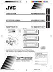
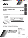
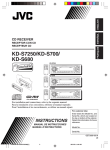
CD RECEIVER
KD-S620/S570
ENGLISH
RECEPTOR CON CD
KD-S620/S570
ESPAÑOL
RECEPTEUR CD
KD-S620/S570
FRANÇAIS
KD-S620
KD-S620
31
KD-S570
KD-S570
COMPACT
For installation and connections, refer to the separate manual.
Para la instalación y las conexiones, refiérase al manual separado.
Pour l’installation et les raccordements, se référer au manuel séparé.
DIGITAL AUDIO
For customer Use:
INSTRUCTIONS
MANUAL DE INSTRUCCIONES
MANUEL D’INSTRUCTIONS
Enter below the Model No. and
Serial No. which are located on
the top or bottom of the cabinet.
Retain this information for future
reference.
Model No.
Serial No.
GET0003-001A
[J]
EN00.KD-S620/S570[J]f
3
11/1/00, 5:28 PM
ENGLISH
INFORMATION (For USA)
This equipment has been tested and found to comply with the limits for a Class B digital
device, pursuant to Part 15 of the FCC Rules. These limits are designed to provide
reasonable protection against harmful interference in a residential installation. This
equipment generates, uses, and can radiate radio frequency energy and, if not installed
and used in accordance with the instructions, may cause harmful interference to radio
communications. However, there is no guarantee that interference will not occur in a
particular installation. If this equipment does cause harmful interference to radio or television
reception, which can be determined by turning the equipment off and on, the user is
encouraged to try to correct the interference by one or more of the following measures:
– Reorient or relocate the receiving antenna.
– Increase the separation between the equipment and receiver.
– Connect the equipment into an outlet on a circuit different from that to which the receiver
is connected.
– Consult the dealer or an experienced radio/TV technician for help.
IMPORTANT FOR LASER PRODUCTS
Precautions:
1. CLASS 1 LASER PRODUCT
2. DANGER: Invisible laser radiation when open and interlock failed or defeated. Avoid direct
exposure to beam.
3. CAUTION: Do not open the top cover. There are no user-serviceable parts inside. Leave
all servicing to qualified service personnel.
4. CAUTION: This CD player uses invisible laser radiation, however, is equipped with safety
switches to prevent radiation emission when unloading CDs. It is dangerous to defeat the
safety switches.
5. CAUTION: Use of controls, adjustments or performance of procedures other than those
specified herein may result in hazardous radiation exposure.
How to reset your unit
Press and hold both the SEL (Select) and
(Standby/On/ATT) buttons at the same time for
several seconds.
This will reset the built-in microcomputer.
NOTES: Your preset adjustments — such as preset
channels or sound adjustments — will also be
erased.
If a CD is in the unit, it will eject when you reset
the unit. Pay attention not to drop the CD.
BEFORE USE
* For safety....
• Do not raise the volume level too much, as this
will block outside sounds, making driving
dangerous.
• Stop the car before performing any complicated
operations.
(Standby/On/ATT)
SEL (Select)
*Temperature inside the car....
If you have parked the car for a long time in hot
or cold weather, wait until the temperature in the
car becomes normal before operating the unit.
2
EN02-04.KD-S620/S570[J]f
2
11/1/00, 5:35 PM
Thank you for purchasing a JVC product. Please read all instructions carefully before operation, to
ensure your complete understanding and to obtain the best possible performance from the unit.
ENGLISH
CONTENTS
How to reset your unit .......................................................................... 2
BASIC OPERATIONS .................................................... 4
RADIO OPERATIONS ................................................... 5
Listening to the radio ..................................................................... 5
Storing stations in memory ............................................................ 6
FM station automatic preset: SSM ............................................... 6
Manual preset .............................................................................. 7
Tuning into a preset station ........................................................... 8
Other convenient tuner functions ................................................. 9
Scanning broadcast stations ........................................................ 9
Selecting FM reception sound ...................................................... 9
CD OPERATIONS ....................................................... 10
Playing a CD ................................................................................. 10
Locating a track or a particular portion on a CD ..................... 11
Selecting CD playback modes ...................................................... 12
Other convenient CD functions ................................................... 12
Prohibiting CD ejection .............................................................. 12
SOUND ADJUSTMENTS ............................................. 13
Adjusting the sound ...................................................................... 13
Turning on/off the loudness function ............................................... 14
Using the Sound Control Memory .............................................. 15
Selecting and storing the sound modes ..................................... 15
Recalling the sound modes ........................................................ 16
Canceling Advanced SCM ........................................................... 17
Storing your own sound adjustments ......................................... 18
OTHER MAIN FUNCTIONS ......................................... 19
Setting the clock ............................................................................ 19
Selecting the level display ............................................................ 20
Detaching the control panel ......................................................... 21
REMOTE OPERATIONS (ONLY FOR KD-S620) ............. 22
Installing the battery .................................................................... 22
Using the remote controller ......................................................... 23
MAINTENANCE ......................................................... 24
Handling CDs ................................................................................ 24
TROUBLESHOOTING ................................................. 25
SPECIFICATIONS ....................................................... 26
3
EN02-04.KD-S620/S570[J]f
3
11/1/00, 5:35 PM
ENGLISH
BASIC OPERATIONS
1
2
3
1
Note:
When you use this unit for the
first time, set the built-in
clock correctly, see page 19.
Turn on the power.
/I/ATT
Note on One-Touch Operation:
When you select a source in step 2 below, the power automatically comes on.
You do not have to press this button to turn on the power.
2
CD
Select the source.
FM
To operate the tuner, see pages 5 – 9.
To operate the CD player, see pages 10 – 12.
AM
3
Adjust the volume.
Volume level appears
Volume level indicator
4
Adjust the sound as you want (see pages 13 – 18).
To drop the volume in a moment
Press
briefly while listening to any source. “ATT” starts flashing on the display, and
the volume level will drop in a moment.
To resume the previous volume level, press the button briefly again.
To turn off the power
Press
for more than 1 second.
4
EN02-04.KD-S620/S570[J]f
4
11/1/00, 5:36 PM
RADIO OPERATIONS
ENGLISH
Listening to the radio
1
2
1
Select the band (FM1, FM2, FM3 or AM).
You can select any one of FM1, FM2 and FM3 to listen to an
FM station.
FM
selected band appears
AM
AM
FM1
FM2
FM3
Volume level indicator
2
To search stations
Start searching a station.
of higher
When a station is received, searching stops.
frequencies.
To search stations
of lower
frequencies.
To stop searching before a station is received, press the same button you have pressed
for searching.
To tune in a particular frequency without searching:
1 Press FM or AM to select the band.
2 Press and hold
¢ or 4
until “M” starts flashing on the display.
Now you can manually change the frequency while “M” is flashing.
3 Press
¢ or 4
repeatedly until the frequency you want is reached.
• If you hold down the button, the frequency keeps changing until you release the button.
5
EN05-09.KD-S620/570[J]f
5
3/25/05, 2:57 AM
ENGLISH
Storing stations in memory
You can use one of the following two methods to store broadcasting stations in memory.
• Automatic preset of FM stations: SSM (Strong-station Sequential Memory)
• Manual preset of both FM and AM stations
FM station automatic preset: SSM
You can preset 6 local FM stations in each FM band (FM1, FM2, and FM3).
1
2
1
FM1
FM2
FM3
FM
Select the FM band number (FM1, FM2 or
FM3) you want to store FM stations into.
2
Press and hold the both buttons for more than
2 seconds.
“SSM” appears, then disappears when
automatic preset is over.
Local FM stations with the strongest signals are searched and stored automatically in the
band number you have selected (FM1, FM2 or FM3). These stations are preset in the number
buttons — No. 1 (lowest frequency) to No. 6 (highest frequency).
When automatic preset is over, the station stored in number button 1 will be automatically
tuned in.
6
EN05-09.KD-S620/570[J]f
6
3/25/05, 2:57 AM
ENGLISH
Manual preset
You can preset up to 6 stations in each band (FM1, FM2, FM3 and AM) manually.
EXAMPLE: Storing an FM station of 88.3 MHz into the preset number 1 of the FM1 band
1
2
3
1
Select the FM1 band.
FM
2
Tune into a station of 88.3 MHz.
See page 5 to tune into a station.
3
Press and hold the button for more than 2
seconds.
“P1” flashes for a few seconds.
4
Repeat the above procedure to store other stations into other
preset numbers.
Notes:
• A previously preset station is erased when a new station is stored in the same preset number.
• Preset stations are erased when the power supply to the memory circuit is interrupted (for example,
during battery replacement). If this occurs, preset the stations again.
7
EN05-09.KD-S620/570[J]f
7
3/25/05, 2:57 AM
ENGLISH
Tuning into a preset station
You can easily tune into a preset station.
Remember that you must store stations first. If you have not stored them yet, see pages 6
and 7.
1
2
1
Select the band (FM1, FM2, FM3 or AM) you
want.
FM
AM
AM
FM1
FM2
FM3
2
Select the number (1 – 6) for the preset station
you want.
8
EN05-09.KD-S620/570[J]f
8
3/25/05, 2:57 AM
ENGLISH
Other convenient tuner functions
MO/RND
RPT/SCAN
Scanning broadcast stations
When you press RPT/SCAN while listening to the radio, station scanning starts. Each time a
broadcast is tuned in, scanning stops for about 5 seconds (tuned frequency number flashes
on the display), and you can check what program is now being broadcasted.
If you want to listen to that program, press the same button again to stop scanning.
Selecting FM reception sound
When an FM stereo broadcast is hard to receive:
Press MO/RND (Mono/Random) while listening to an FM stereo broadcast. The sound you
hear becomes monaural but reception will be improved.
A
Lights up when receiving an FM broadcast in stereo.
To restore the stereo effect, press the same button again.
9
EN05-09.KD-S620/570[J]f
9
3/25/05, 2:58 AM
ENGLISH
CD OPERATIONS
Playing a CD
0
1
1
Insert a disc into the loading slot.
The unit turns on, draws a CD and starts playback
automatically.
• When a CD is inserted upside down, “EJECT” appears on
the display and the CD automatically ejects.
A
A
Total playing time of
the inserted disc
Total track number
of the inserted disc
Elapsed playing
time
Current track
Note on One-Touch Operation:
When a CD is already in the loading slot, pressing CD turns on the unit and starts playback
automatically.
CAUTION on Volume Setting
CDs produces very little noise compared with other sources. If the volume level is adjusted
for the tuner, for example, the speakers may be damaged by the sudden increase in the
output level. Therefore, lower the volume before playing a CD and adjust it as required
during playback.
To stop play and eject the CD
Press 0.
CD play stops and the CD automatically ejects from the loading slot. The source changes to
the tuner (you will hear the last received station).
If you change the source to AM/FM, the CD play also stops (without ejecting the CD this
time).
• If the ejected disc is not removed for about 15 seconds, the disc is automatically inserted again into
the loading slot to protect it from dust. (CD play will not start this time.)
• You can eject the CD even when the unit is turned off.
10
EN10-12.KD-S620/S570[J]f
10
11/1/00, 5:41 PM
¢
4
ENGLISH
Locating a track or a particular portion on a CD
Number buttons
To fast forward or reverse the track
Press and hold
¢, while playing a CD, to fast forward the track.
Press and hold 4
, while playing a CD, to reverse the track.
To go to the next track or the previous track
Press
¢ briefly, while playing a CD, to go ahead to the beginning
of the next track. Each time you press the button consecutively, the
beginning of the next tracks is located and played back.
briefly, while playing a CD, to go back to the beginning of
Press 4
the current track. Each time you press the button consecutively, the
beginning of the previous tracks is located and played back.
To go to a particular track directly
7
8
9
10
11
12
Press the number button corresponding to the track number to start its
playback.
• To select a track number from 1 – 6:
Press 1 (7) – 6 (12) briefly.
• To select a track number from 7 – 12:
Press and hold 1 (7) – 6 (12) for more than 1 second.
11
EN10-12.KD-S620/S570[J]f
11
11/1/00, 5:41 PM
ENGLISH
Selecting CD playback modes
MO/RND
RPT/SCAN
To play back tracks at random (Random Play)
You can play back all tracks on the CD at random.
MO/RND
Each time you press MO/RND (Mono/Random) while playing a CD, CD
random play mode turns on and off alternatively.
When the random mode is turned on, the RND indicator lights up on the
display and a track randomly selected starts playing.
To play back tracks repeatedly (Repeat Play)
You can play back the current track repeatedly.
RPT
SCAN
Each time you press RPT/SCAN (Repeat/Scan) while playing a CD, CD
repeat play mode turns on and off alternatively.
When the repeat mode is turned on, the RPT indicator lights up on the
display.
Track number of the currently playing track
Other convenient CD functions
Prohibiting CD ejection
You can prohibit the CD ejection and can “lock” a CD in the loading slot.
Press and hold CD and 0 for more than 2 seconds. “EJECT” flashes on the display for about
5 seconds, and the CD is “locked.”
To cancel the prohibition and “unlock” the CD, press and hold CD and 0 for more than 2
seconds again. “EJECT” appears on the display, and the CD ejects from the loading slot.
12
EN10-12.KD-S620/S570[J]f
12
11/1/00, 5:42 PM
SOUND ADJUSTMENTS
ENGLISH
Adjusting the sound
You can adjust the treble/bass sound and the speaker balance.
2
1
Equalization pattern indicator
1
Select the item you want to adjust.
Indication
To do:
Range
BAS
(Bass)
Adjust the bass
–06 (min.) — +06 (max.)
TRE
(Treble)
Adjust the treble
–06 (min.) — +06 (max.)
FAD
(Fader)*
Adjust the front and rear speaker
balance
R06 (rear only) — F06 (front only)
BAL
(Balance)
Adjust the left and right speaker
balance
L06 (left only) — R06 (right only)
VOL
(Volume)
Adjust the volume
00 (min.) — 50 (max.)
Note:
* If you are using a two-speaker system, set the fader level to “00.”
2
Adjust the level.
Equalization pattern changes as
you adjust the bass or treble.
Note:
Normally the + and – buttons works as the volume control.
So you do not have to select “VOL” to adjust the volume level.
13
EN13-18.KD-S620/570[J]f
13
11/1/00, 5:55 PM
ENGLISH
Turning on/off the loudness function
The human ear is less sensitive to low and high frequencies at low volumes.
The loudness function can boost these frequencies to produce well-balanced sound at low
volume level.
Each time you press LOUD, the loudness function turns on and off alternatively.
LOUD
@
A
14
EN13-18.KD-S620/570[J]f
14
11/1/00, 5:55 PM
ENGLISH
Using the Sound Control Memory
You can select and store a preset sound adjustment suitable to each playback source.
(Advanced SCM)
Selecting and storing the sound modes
Once you select a sound mode, it is stored in memory, and will be recalled every time you
select the same source. A sound mode can be stored each of the following sources — FM1,
FM2, FM3, AM and CD.
• If you do not want to store the sound mode separately for each playback source, but want to
use the same sound mode for all the sources, see “Canceling Advanced SCM” on page 17.
“SCM” indicator
and sound mode
indicators
1
Equalization pattern indicator
1
SCM
Select the sound mode you want.
Each time you press the button, the sound mode changes as follows.
• When “SCM LINK” is set to “LINK ON”, the selected sound mode can
be stored in memory for the current source and the effect applies only
to the current source. Each time you change the playback source, the
SCM indicator flashes on the display.
• When “SCM LINK” is set to “LINK OFF”, the selected sound mode
effect applies to any source.
Indication
For:
Preset values
Bass
Treble
Loudness
SCM OFF
(Flat sound)
00
00
On
BEAT
Rock or disco music
+02
00
On
SOFT
Quiet background music
+01
–03
Off
POP
Light music
+04
+01
Off
15
EN13-18.KD-S620/570[J]f
15
11/1/00, 5:55 PM
ENGLISH
Recalling the sound modes
1
1
Select the source while the “SCM” indicator
is lit on the display.
CD
FM
The “SCM” indicator starts flashing, and the sound mode
stored in memory for the selected source is recalled.
AM
Sound mode
indicator
Notes:
• You can adjust each sound mode to your preference, and store it in memory.
If you want to adjust and store your original sound mode, see “Storing your own sound adjustments”
on page 18.
• To adjust the bass and treble reinforcement levels or to turn on/off the loudness function temporarily,
see pages 13 and 14. (Your adjustments will be cancelled if another source is selected.)
16
EN13-18.KD-S620/570[J]f
16
11/1/00, 5:56 PM
ENGLISH
Canceling Advanced SCM
You can cancel the Advanced SCM (Sound Control Memory), and unlink the sound modes
and the playback sources.
When shipped from the factory, a different sound mode can be stored in memory for each
source so that you can change the sound modes simply by changing the sources.
LINK ON: Advanced SCM (different SCMs for different sources)
LINK OFF: Conventional SCM (one SCM for all sources)
3
1,4 2
1
Press and hold SEL for more than 2 seconds.
“CLOCK H”, “CLOCK M”, “SCM LINK” or “LEVEL” appears
on the display.
2
Select “SCM LINK” if not shown on the display.
3
Select the desired mode — “LINK ON” or
“LINK OFF”.
4
Finish the setting.
17
EN13-18.KD-S620/570[J]f
17
11/1/00, 5:56 PM
ENGLISH
Storing your own sound adjustments
You can adjust the sound modes (BEAT, SOFT, POP: see page 15) to your preference and
store your own adjustments in memory.
3
1
2
2
1,4
SCM
Call up the sound mode you want to adjust.
See page 13 for details.
Within
5 seconds
2
To adjust the bass or treble sound level
Select “BAS” or “TRE.”
To turn on or off the loudness function
LOUD
Each time you press LOUD, the loudness function turns on and off
alternatively. (= go to step 4)
Within
5 seconds
3
Adjust the bass or treble level.
See page 13 for details.
4
Within
5 seconds
Press and hold SCM until the sound mode
you have selected in step 1 flashes on the
display.
SCM
Your setting is stored in memory.
5
Repeat the same procedure to store other settings.
To reset to the factory settings
Repeat the same procedure and reassign the preset values listed in the table on page 15.
18
EN13-18.KD-S620/570[J]f
18
11/1/00, 5:56 PM
OTHER MAIN FUNCTIONS
ENGLISH
Setting the clock
2,3 1,4 2,3
1
DISP
Press and hold the button for more than
2 seconds.
“CLOCK H”, “CLOCK M”, “SCM LINK” or “LEVEL”
appears on the display.
2
1.
Set the hour.
1. Select “CLOCK H” if not shown on the
display.
2.
2. Adjust the hour.
3
1.
Set the minute.
1. Select “CLOCK M.”
2.
2. Adjust the minute.
4
Start the clock.
To check the current clock time (changing the display mode)
Press DISP repeatedly. Each time you press the button, the display mode changes as follows.
During tuner operation:
Frequency
During CD operation:
Clock
Elapsed
playing time
Clock
• If the unit is not in use when you press DISP, the power turns on, the clock time is shown for
5 seconds, then the power turns off.
EN19-21.KD-S620/570[J]f
19
11/1/00, 5:58 PM
19
ENGLISH
Selecting the level display
You can select the level display according to your preference.
When shipped from the factory, “VOL 2” is selected.
VOL 1: Shows the volume level indicator and the equalization pattern indicator.
VOL 2: Alternates “VOL 1” setting and illumination display.
OFF: Erase the volume level indicator and the equalization pattern indicator.
3 1,4 2
1
Volume level indicator
Equalization pattern indicator
Press and hold SEL for more than 2 seconds.
“CLOCK H”, “CLOCK M”, “SCM LINK” or “LEVEL” appears
on the display.
2
Select “LEVEL” if not shown on the display.
3
Select the desired mode — “VOL 1”, “VOL 2”
or “OFF”.
4
Finish the setting.
20
EN19-21.KD-S620/570[J]f
20
11/1/00, 5:58 PM
ENGLISH
Detaching the control panel
You can detach the control panel when leaving the car.
When detaching or attaching the control panel, be careful not to damage the connectors on
the back of the control panel and on the panel holder.
How to detach the control
panel
Before detaching the control panel, be sure
to turn off the power.
1
2
3
How to attach the control
panel
1
Unlock the control panel.
2
Lift and pull the control panel
out of the unit.
Put the detached control
panel into the case provided.
Insert the left side of the
control panel into the groove
on the panel holder.
Press the right side of the
control panel to fix it to the
panel holder.
Note on cleaning the connectors:
If you frequently detach the control panel, the
connectors will deteriorate.
To minimize this possibility, periodically wipe
the connectors with a cotton swab or cloth
moistened with alcohol, being careful not to
damage the connectors.
Connectors
21
EN19-21.KD-S620/570[J]f
21
11/1/00, 5:58 PM
REMOTE OPERATIONS
Remote sensor
ENGLISH
This section is ONLY FOR KD-S620.
Before using the remote controller:
• Aim the remote controller directly at the remote sensor on
the main unit. Make sure there is no obstacle in between.
• Do not expose the remote sensor to strong light (direct
sunlight or artificial lighting).
Installing the battery
When the controllable range or effectiveness of the remote controller decreases, replace
the battery.
(back side)
1)
2)
Lithium coin battery
(product number:
CR2025)
1. Remove the battery holder.
1) Push out in the direction indicated by the arrow
using a ball point pen or a similar tool.
2) Remove the battery holder.
2. Place the battery.
Slide the battery into the holder with the + side facing
upwards so that the battery is fixed in the holder.
3. Return the battery holder.
Insert again the battery holder pushing it until you hear
a clicking sound.
(back side)
WARNING:
• Store the batteries in a place which children cannot reach.
If a child accidentally swallows the battery, immediately consult a doctor.
• Do not recharge, short, disassemble or heat the batteries or dispose of in a fire.
Doing any of these things may cause the batteries to give off heat, crack or start a fire.
• Do not leave the batteries with other metallic materials.
Doing this may cause the batteries to give off heat, crack or start a fire.
• When throwing away or saving the batteries, wrap in tape and insulate; otherwise, , it may cause
the batteries to give off heat, crack or start a fire.
• Do not poke the batteries with tweezers or similar tools.
Doing this may cause the batteries to give off heat, crack or start a fire.
22
EN22-23.KD-S620/570[J]f
22
11/1/00, 6:06 PM
5
6
1
2
7
3
4
RM-RK31
For KD-S620
1 Functions the same as the
button on the main unit.
2 • Functions as the BAND button while listening to the radio.
Each time you press the button, the band changes.
• Does not function as the PROG button.
3 • Functions as the PRESET button while listening to the radio.
Each time you press the button, the preset station number
increases, and the selected station is tuned in.
4 Functions the same as the + and – buttons on the main unit.
Note: These buttons cannot be used for the clock (CLOCK H,
CLOCK M), SCM LINK and LEVEL (see pages 19, 17 and
20).
5 Selects the sound mode.
Each time you press SCM (Sound Control Memory), the mode
changes.
6 Selects the source.
Each time you press FUNC (function), the source changes.
7 • Searches stations while listening to the radio.
• Fast forwards or reverses the track if pressed and held while
listening to a CD.
• Skips to the beginning of the next tracks or goes back to the
beginning of the current (or previous tracks) if pressed briefly
while listening to a CD.
23
EN22-23.KD-S620/570[J]f
23
11/1/00, 6:06 PM
ENGLISH
Using the remote controller
ENGLISH
MAINTENANCE
Handling CDs
COMPACT
This unit has been designed only to reproduce the CDs bearing the
Other discs cannot be played back.
mark.
DIGITAL AUDIO
How to handle CDs
When removing a CD from its case, press down the center holder of the case
and lift the CD out, holding it by the edges.
• Always hold the CD by the edges. Do not touch its recording surface.
When storing a CD into its case, gently insert the CD around the center
holder (with the printed surface facing up).
• Make sure to store CDs into the cases after use.
Center holder
To keep CDs clean
A dirty CD may not play correctly. If a CD does becomes dirty, wipe it with a soft
cloth in a straight line from center to edge.
To play new CDs
New CDs may have some rough spots around the inner and outer edges. If such
a CD is used, this unit may reject the CD.
To remove these rough spots, rub the edges with a pencil or ball-point pen, etc.
Moisture condensation
Moisture may condense on the lens inside the CD player in the following cases:
• After starting the heater in the car.
• If it becomes very humid inside the car.
Should this occur, the CD player may malfunction. In this case, eject the CD and leave the unit turned on
for a few hours until the moisture evaporates.
CAUTIONS:
• Do not insert 8cm (3 3/16") CDs (single CDs) into the loading slot. (Such CDs cannot be ejected.)
• Do not insert any CD of unusual shape – like a heart or flower; otherwise, it will cause a malfunction.
• Do not expose CDs to direct sunlight or any heat source or place them in a place subject to high temperature
and humidity. Do not leave them in a car.
• Do not use any solvent (for example, conventional record cleaner, spray, thinner, benzine, etc.) to clean
CDs.
When playing a CD-R (Recordable)
You can play back your original CD-Rs on this recevier.
• Before playing back CD-Rs, read their instructions or cautions carefully.
• Some CD-Rs recorded on CD recorders may not be played back on this receiver because of their disc
characteristics, and of the following reasons:
– Discs are dirty or scratched.
– Moisture condensation occurs on the lens inside the unit.
– The pickup lens inside the CD player is dirty.
• Use only “finalized” CD-Rs.
• CD-RWs (Rewritable) cannot be played back on this recevier.
About mistracking:
Mistracking may result from driving on extremely rough roads. This does not damage the unit and
the CD, but will be annoying.
We recommend that you stop CD play while driving on such rough roads.
24
EN24-26.KD-S620/570[J]f
24
11/1/00, 6:06 PM
TROUBLESHOOTING
Causes
Symptoms
Remedies
• CD cannot be played back.
CD is inserted upside down.
Insert the CD correctly.
• CD sound is sometimes
interrupted.
You are driving on rough
roads.
Stop CD play while driving
rough roads.
CD is scratched.
Change the CD.
Connections are incorrect.
Check the cords and
connections.
No CD is in the loading slot.
Insert a CD into the loading
slot.
CD is inserted incorrectly.
Insert it correctly.
The volume control is turned
to the minimum level.
Adjust it to the optimum level.
Connections are incorrect.
Check the cords and
connections.
• SSM (Strong-station
Sequential Memory)
automatic preset does not
work.
Signals are too weak.
Store stations manually.
• Static noise while listening
to the radio.
The antenna is not connected
firmly.
Connect the antenna firmly.
• CD can be neither played
back nor ejected.
The CD player may function
incorrectly.
Press
and 0 at the
same time for more than 2
seconds. Be careful not to
drop CD when it is ejected.
• The unit does not work at
all.
The built-in microcomputer
and SEL at
Press
may function incorrectly due to the same time for more than 2
noise, etc.
seconds to reset the unit. (The
clock setting and preset
stations stored in memory are
erased.) (See page 2.)
• “NO DISC” appears on the
display.
• Sound cannot be heard from
the speakers.
ENGLISH
What appears to be trouble is not always serious. Check the following points before calling a
service center.
25
EN24-26.KD-S620/570[J]f
25
11/1/00, 6:07 PM
ENGLISH
SPECIFICATIONS
AUDIO AMPLIFIER SECTION
CD PLAYER SECTION
Maximum Power Output:
Front: 40 watts per channel
Rear: 40 watts per channel
Continuous Power Output (RMS):
Front: 16 watts per channel into 4 Ω,
40 Hz to 20 000 Hz at no more
than 0.8% total harmonic
distortion.
Rear: 16 watts per channel into 4 Ω,
40 Hz to 20 000 Hz at no more
than 0.8% total harmonic
distortion.
Load Impedance: 4 Ω (4 Ω to 8 Ω allowance)
Tone Control Range
Bass: ±10 dB at 100 Hz
Treble:±10 dB at 10 kHz
Frequency Response: 40 Hz to 20 000 Hz
Signal-to-Noise Ratio: 70 dB
Line-Out Level/Impedance: 2.0 V/20 kΩ load
(full scale)
Output Impedance: 1 kΩ
Type: Compact disc player
Signal Detection System: Non-contact optical
pickup (semiconductor laser)
Number of channels: 2 channels (stereo)
Frequency Response: 5 Hz to 20 000 Hz
Dynamic Range: 96 dB
Signal-to-Noise Ratio: 98 dB
Wow and Flutter: Less than measurable limit
GENERAL
TUNER SECTION
Power Requirement
Operating Voltage: DC 14.4 volts (11 volts to
16 volts allowance)
Allowable Working Temperature:
0°C to +40°C (32°F to 104°F)
Grounding System: Negative ground
Dimensions (W x H x D)
Installation Size:
182 mm x 52 mm x 150 mm
(7-3/16" x 2-1/16" x 5-15/16")
Panel Size: 188 mm x 58 mm x 14 mm
(7-7/16" x 2-5/16" x 5/8")
Mass: 1.3 kg (2.9 lbs) (excluding accessories)
Frequency Range
FM: 87.5 MHz to 107.9 MHz
AM: 530 kHz to 1 710 kHz
Design and specifications subject to change
without notice.
[FM Tuner]
Usable Sensitivity: 11.3 dBf (1.0 µV/75 Ω)
50 dB Quieting Sensitivity:
16.3 dBf (1.8 µV/75 Ω)
Alternate Channel Selectivity (400 kHz):
65 dB
Frequency Response: 40 Hz to 15 000 Hz
Stereo Separation: 35 dB
Capture Ratio: 1.5 dB
If a kit is necessary for your car, consult
your telephone directory for the nearest
car audio speciality shop.
[AM Tuner]
Sensitivity: 20 µV
Selectivity: 35 dB
26
EN24-26.KD-S620/570[J]f
26
11/1/00, 6:07 PM
http://www.jvcmobile.com
Visit us on-line for
Technical Support & Customer Satisfaction Survey.
US RESIDENTS ONLY
Having TROUBLE with operation?
Please reset your unit
Refer to page of How to Reset
Still having trouble??
USA ONLY
Call 1-800-252-5722
http://www.jvcservice.com
We can help you!
VICTOR COMPANY OF JAPAN, LIMITED
EN, SP, FR
V
J
EN00.KD-S620/S570[J]f
2
C
0800HISFLEJES
11/1/00, 5:28 PM
KD-S620
KD-S570
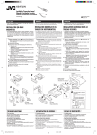
Installation/Connection Manual
Manual de instalación/conexión
Manuel d’installation/raccordement
V
J
GET0003-002A
[J]
ENGLISH
ESPAÑOL
C
0800HISFLEJES
EN, SP, FR
FRANÇAIS
• This unit is designed to operate on 12 volts DC, NEGATIVE
ground electrical systems.
• Esta unidad está diseñada para funcionar con 12 voltios de
CC, con sistemas eléctricos de masa NEGATIVA.
• Cet appareil est conçu pour fonctionner sur des sources de
courant continu de 12 volts à masse NEGATIVE.
INSTALLATION (IN-DASH
MOUNTING)
INSTALACION (MONTAJE EN EL
TABLERO DE INSTRUMENTOS)
INSTALLATION (MONTAGE DANS LE
TABLEAU DE BORD)
• The following illustration shows a typical installation. However,
you should make adjustments corresponding to your specific
car. If you have any questions or require information regarding
installation kits, consult your JVC car audio dealer or a company
supplying kits.
• La siguiente ilustración muestra una instalación típica. Sin
embargo usted deberá efectuar los ajustes correspondientes
a su automóvil. Si tiene alguna pregunta o necesita información
acerca de las herramientas para instalación, consulte con su
concesionario de JVC de equipos de audio para automóviles o
a una compañía que suministra tales herramientas.
• L’illustration suivante est un exemple d’installation typique.
Cependant, vous devez faire les ajustements correspondant à
votre voiture particulière. Si vous avez des questions ou avez
besoin d’information sur des kits d’installation, consulter votre
revendeur d’autoradios JVC ou une compagnie
d’approvisionnement.
1
2
3
4
5
6
7
8
9
1
Before mounting: Press
(Control Panel Release) to
detach the control panel if already attached.
* When shipped from the factory, the control panel is packed
in the hard case
Remove the trim plate.
Remove the sleeve after disengaging the sleeve locks.
1 Stand the unit.
Note: When you stand the unit, be careful not to damage
the fuse on the rear.
2 Insert the 2 handles between the unit and the sleeve, as
illustrated, to disengage the sleeve locks.
3 Remove the sleeve.
Note: Be sure to keep the handles for future use after
installing the unit.
Install the sleeve into the dashboard.
* After the sleeve is correctly installed in the dashboard,
bend the appropriate tabs to hold the sleeve firmly in place,
as illustrated.
Fix the mounting bolt to the rear of the unit’s body and place
the rubber cushion over the end of the bolt.
Do the required electrical connections explained on the back
of this instructions.
Slide the unit into the sleeve until it is locked.
Attach the trim plate so that the projection on the trim plate
is fixed to the left side of the unit.
Attach the control panel.
2
3
4
5
6
7
8
9
1
Antes de instalar: Pulse
(soltar panel de control) para
separar el panel de control si ya está unido.
* Cuando se envía de la fábrica, el panel de control está
embalado en el estuche duro.
Retire la placa de guarnición.
Retire la cubierta después de desenganchar los retenes
de la cubierta.
1 Ponga la unidad vertical.
Nota: Al poner la unidad vertical, tenga cuidado de no
dañar el fusible provisto en la parte posterior.
2 Inserte las dos asas entre la unidad y la cubierta tal
como en la ilustración y desenganche los retenes de la
cubierta.
3 Retire la cubierta.
Nota: Después de instalar la unidad, asegúrese de
guardar las asas para uso futuro.
Instale la cubierta en el tablero de instrumentos.
* Después de que la cubierta esté correctamente instalada
en el tablero de instrumentos, doble las lengüetas
correspondientes para sostener la cubierta firmemente
en su lugar, tal como se muestra.
Fixe el perno de montaje ou la parte trasera del cuerpo de la
unidad y coloque el cojín de goma sobre el extremo del perno.
Realice las conexiones eléctricas requeridas en base a
las explicaciones que figuran en la parte de atrás de estas
instrucciones.
Deslice la unidad dentro de la cubierta hasta que quede
trabada.
Coloque la placa de guarnición de manera que el saliente de
la misma quede colocado en el lateral izquierdo de la unidad.
Coloque el panel de control.
1
2
3
4
5
6
7
8
9
Avant le montage: Appuyez sur
(déblocage du
panneau de commande) pour éventuellement détacher le
panneau de commande.
* Lorsque ce panneau de commande sort d’usine, il est
rangé dans un étui de transport.
Retirer la plaque d’assemblage.
Libérer les verrous du manchon et retirer le manchon.
1 Poser l’appareil à la verticale.
Remarque: Lorsque vous mettez l’appareil à la verticale,
faire attention de ne pas endommager le fusible situé
sur le fond.
2 Insérer les 2 poignées entre l’appareil et le manchon
comme indiqué pour désengagé les verrous de manchon.
3 Retirer le manchon.
Remarque: S'assurer de garder les poignées pour une
utilisation ultérieur, après l'installation de l'appareil.
Installer le manchon dans le tableau de bord.
* Après installation correcte du manchon dans le tableau
de bord, plier les bonnes pattes pour maintenir fermement
le manchon en place, comme montré.
Monter le boulon de montage sur l’arrière du corps de
l’appareil puis passer l’amortisseur en caoutchouc sur
l’extrémité du boulon.
Réalisez les connexions électriques expliquées au dos de
cette page.
Faire glisser l’appareil dans le manchon jusqu’à ce qu’il soit
verrouillé.
Attachez la plaque d’ajustage de façon que la projection de
la plaque soit fixée sur le cote gauche de l’appareil.
Remonter le panneau de commande.
2
Dashboard
Tablero de instrumentos
Tableau de bord
Rubber cushion
Cojín de goma
Amortisseur en caoutchouc
4
Sleeve
Cubierta
Manchon
7
3
Sleeve
Cubierta
Manchon
Fuse
Fusible
Fusible
Slot
Ranura
Fente
1
53
5
mm
6
See the back page for electrical
connections.
Con respecto a las conexiones
eléctricas, consulte la página de
atrás.
Voir le dos de cette page pour les
connexions électriques.
2
Trim plate
Placa de guarnición
Plaque d’assemblage
3
1
1
2
3
4
Lock Plate
Placa de bloqueo
Plaque de verrouillage
The fuse blows.
Are the red and black leads connected correctly?
Power cannot be turned on.
Is the yellow lead connected?
No sound from the speakers.
Is the speaker output lead short-circuited?
Sound is distorted.
Is the speaker output lead grounded?
Are the “–” terminals of L and R speakers grounded in common?
Unit becomes hot.
Is the speaker output lead grounded?
Are the “–” terminals of L and R speakers grounded in common?
EN.SP.FR.KD-S620/570[J]f
m
10
TROUBLESHOOTING
•
*
•
*
•
*
•
*
*
•
*
*
4*
9
10
4m
Mounting bolt
Perno de montaje
Boulon de montage
8
Handle
Manija
Poignée
18
5
LOCALIZACION DE AVERIAS
EN CAS DE DIFFICULTÉS
•
*
•
*
•
*
•
*
*
El fusible se quema.
¿Están los conductores rojo y negro correctamente conectados?
No es posible conectar la alimentación.
¿Está el cable amarillo conectado?
No sale sonido de los altavoces.
¿Está el cable de salida del altavoz cortocircuitado?
El sonido presenta distorsión.
¿Está el cable de salida del altavoz conectado a masa?
¿Están los terminales “–” de los altavoces L y R conectados a
una masa común?
• La unidad se calienta.
* ¿Está el cable de salida del altavoz conectado a masa?
* ¿Están los terminales “–” de los altavoces L y R conectados a
una masa común?
11/1/00, 7:45 PM
•
*
•
*
•
*
•
*
*
Le fusible saute.
Les fils rouge et noir sont-ils racordés correctement?
L’appareil ne peut pas être mise sous tension.
Le fil jaune est-elle raccordée?
Pas de son des haut-parleurs.
Le fil de sortie de haut-parleur est-il court-circuité?
Le son est déformé.
Le fil de sortie de haut-parleur est-il à la masse?
Les bornes “–” des haut-parleurs gauche et droit sont-elles mises
ensemble à la masse?
• L’appareil devient chaud.
* Le fil de sortie de haut-parleur est-il à la masse?
* Les bornes “–” des haut-parleurs gauche et droit sont-elles mises
ensemble à la masse?
• When installing the unit without using the sleeve
• Instalación de la unidad sin utilizar la cubierta
• Lors de l'installation de l’appareil sans utiliser de manchon
• When using the optional stay
• Cuando emplea un soporte opcional
• Lors de l'utilisation du hauban en option
In a Toyota for example, first remove the car radio and install the unit in its place.
En un Toyota por ejemplo, primero extraiga la radio del automóvil y luego instale la unidad en su
lugar.
Par exemple dans une Toyota, retirer d’abord l’autoradio et installer l’appareil à la place.
Fire wall
Tabique a prueba de incendios
Cloison
Dashboard
Tablero de instrumentos
Tableau de bord
Flat type screws (M5 x 6 mm)*
Tornillos tipo plano (M5 x 6 mm)*
Vis à tête plate (M5 x 6 mm)*
* Not included with this unit.
* No suministrado con esta unidad.
* Non fourni avec cet appareil.
Stay (option)
Soporte (opción)
Hauban (en option)
Washer
Arandela
Rondelle
Lock nut
Tuerca de seguridad
Ecrou d’arrêt
Screw (option)
Tornillo (opción)
Vis (en option)
Mounting bolt
Perno de montaje
Boulon de montage
Sleeve
Cubierta
Manchon
Bracket*
Ménsula*
Support*
Pocket
Compartimiento
Poche
Bracket*
Ménsula*
Support*
Flat type screws (M5 x 6 mm)*
Tornillos tipo plano (M5 x 6 mm)*
Vis à tête plate (M5 x 6 mm)*
Note: When installing the unit on the mounting bracket, make sure to use the 6 mm-long screws. If
longer screws are used, they could damage the unit.
Nota: Cuando instala la unidad en la ménsula de montaje, asegúrese de utilizar los tornillos de 6
mm de longitud. Si se utilizan tornillos más largos, éstos pueden dañar la unidad.
Remarque: Lors de l'installation de l’appareil sur le support de montage, s’assurer d’utiliser des vis
d’une longueur de 6 mm. Si des vis plus longues sont utilisées, elles peuvent endommager l’appareil.
Removing the unit
Extracción de la unidad
Retrait de l’appareil
• Before removing the unit, release the rear section.
• Antes de extraer la unidad, libere la sección trasera.
• Avant de retirer l’appareil, libérer la section arrière.
1
Remove the control panel.
1
Extraiga el panel de control.
1
Retirer le panneau de commande.
2
Remove the trim plate.
2
Retire la placa de guarnición.
2
Retirer la plaque d’assemblage.
3
Insert the 2 handles into the slots, as shown. Then, while gently
pulling the handles away from each other, slide out the unit.
(Be sure to keep the handles after installing it.)
3
Inserte las 2 manijas entre las ranuras, como se muestra.
Luego, separe gentilmente las manijas y extraiga la unidad.
(Asegúrese de conservar las manijas después de
instalarlo.)
3
Introduire les deux poignées dans les fentes, comme montré.
Puis, tout en tirant doucement les poignées écartées, faire
glisser l’appareil pour le sortir. (S'assurer de conserver les
poignées après l’installation de l’appareil.)
1
3
2
Handle
Manija
Poignée
Parts list for installation and connection
Lista de piezas para instalación y conexión
The following parts are provided with this unit.
After checking them, please set them correctly.
Con esta unidad se suministran las siguientes piezas.
Después de inspeccionarlas, colóquelas correctamente.
Hard case/Control Panel
Estuche duro/Panel de
control
Etui de transport /Panneau
de command
Sleeve
Cubierta
Manchon
Handles
Manijas
Poignées
Washer (ø5)
Arandela (ø5)
Rondelle (ø5)
Lock nut (M5)
Tuerca de seguridad (M5)
Ecrou d’arrêt (M5)
Mounting bolt (M5 x 20 mm)
Perno de montaje (M5 x 20 mm)
Boulon de montage (M5 x 20 mm)
Les pièces suivantes sont fournies avec cet appareil.
Après vérification, veuillez les placer correctement.
FOR KD-S620
PARA KD-S620
POUR LES KD-S620
Remote controller
Mando a distancia
Télécommande
Trim plate
Placa de guarnición
Plaque d’assemblage
Power cord
Cordón de alimentación
Cordon d’alimentation
Liste des pièces pour l’installation et
raccordement
Rubber cushion
Cojín de goma
Amortisseur en caoutchouc
Battery
Pila
Pile
CR2025
EN.SP.FR.KD-S620/570[J]f
2
11/1/00, 7:45 PM
ENGLISH
ESPAÑOL
FRANÇAIS
ELECTRICAL CONNECTIONS
CONEXIONES ELECTRICAS
RACCORDEMENTS ELECTRIQUES
To prevent short circuits, we recommend that you disconnect the
battery’s negative terminal and make all electrical connections
before installing the unit. If you are not sure how to install this unit
correctly, have it installed by a qualified technician.
Para evitar cortocircuitos, recomendamos que desconecte el
terminal negativo de la batería y que efectúe todas las conexiones
eléctricas antes de instalar la unidad. Si usted no está seguro de
cómo instalar correctamente la unidad, hágala instalar por un
técnico cualificado.
Pour éviter tout court-circuit, nous vous recommandons de
débrancher la borne négative de la batterie et d’effectuer tous les
raccordements électriques avant d’installer l’appareil. Si l'on n’est
pas sûr de pouvoir installer correctement cet appareil, le faire
installer par un technicien qualifié.
Nota:
Esta unidad está diseñada para funcionar con 12 voltios de CC,
con sistemas eléctricos de masa NEGATIVA solamente. Si su
vehículo no posee este sistema, será necesario un inversor de
tensión, que puede ser adquirido en los concesionarios de JVC
de equipos de audio para automóviles.
• Reemplace el fusible por uno con la corriente especificada. Si
el fusible se quemase frecuentemente consulte con su
concesionario de JVC de equipos de audio para automóviles.
• Si el ruido fuese un problema...
Esta unidad tiene un filtro de ruido en el circuito de alimentación.
Sin embargo, en algunos vehículos, pueden producirse
chasquidos u otros ruidos indeseados. En tal caso conecte el
terminal de tierra posterior (Ver diagrama de conexión abajo.)
del receptor al chasis del automóvil, utilizando cordones más
gruesos y cortos tales como alambre de cobre trenzado o de
grueso calibre. Si el ruido persiste, consulte a su concesionario
de JVC de equipos de audio para automóvil.
• La entrada máxima de los altavoces traseros debe ser mayor
de 40 vatios y la de los delanteros de 40 vatios, con una
impedancia de 4 a 8 ohmios.
• Asegúrese de conectar esta unidad a tierra en el chasis del
automóvil.
• El sumidero térmico estará muy caliente después del uso.
Asegúrese de no tocarlo al desmontar esta unidad.
Remarque:
Cet appareil est conçu pour fonctionner sur des sources de courant
continu de 12 volts à masse NEGATIVE seulement. Si votre
véhicule n’offre pas ce type d’alimentation, il vous faut un
convertisseur de tension, que vous pouvez acheter chez un
revendeur d’autoradios JVC.
• Remplacer le fusible par un de la valeur précisée. Si le fusible
saute souvent, consulter votre revendeur d’autoradios JVC.
• Si le bruit est un problème...
Cet appareil incorpore un filtre de bruit dans le circuit
d’alimentation. Cependant, avec certains véhicules, quelques
claquements ou autres bruits non désirés risquent de se produire.
Si cela arrive, raccorder la borne de masse arrière de l’appareil
au châssis de la voiture (voir le schéma de raccordement cidessous) en utilisant des cordons les plus gros et les plus courts
possibles telle qu'une barre de cuivre ou une tresse. Si le bruit
persiste, consulter votre revendeur d’autoradios JVC.
• La puissance admissible des haut-parleurs doit être supérieure
à 40 watts à l’arrière et à 40 watts l’avant, avec une impédance
de 4 à 8 ohms.
• S'assurer de raccorder la mise à la masse de cet appareil
au châssis de la voiture.
• Le radiateur devient très chaud après usage. Faire attention de
ne pas le toucher en retirant cet appareil.
Note:
This unit is designed to operate only on 12 volts DC, NEGATIVE
ground electrical systems. If your vehicle does not have this
system, a voltage inverter is required, which can be purchased at
JVC car audio dealers.
• Replace the fuse with one of the specified rating. If the fuse
blows frequently, consult your JVC car audio dealer.
• If noise is a problem...
This unit incorporates a noise filter in the power circuit. However,
with some vehicles, clicking or other unwanted noise may occur.
If this happens, connect the unit’s rear ground terminal (See
connection diagram below.) to the car’s chassis using shorter
and thicker cords, such as copper braiding or gauge wire. If noise
still persists, consult your JVC car audio dealer.
• Maximum input of the speakers should be more than 40 watts at
the rear and 40 watts at the front, with an impedance of 4 to 8
ohms.
• Be sure to ground this unit to the car’s chassis.
• The heat sink becomes very hot after use. Be careful not to
touch it when removing this unit.
Heat sink
Sumidero térmico
Dissipateur de chaleur
A Typical Connections / Conexiones típicas / Raccordements typiques
Before connecting: Check the wiring in the vehicle carefully not
to fail in connecting this unit. Incorrect connection may cause a
serious damage to this unit.
1
2
3
Connect the colored leads of the power cord to the car battery,
speakers and automatic antenna (if any) in the following
sequence.
1 Black: ground
2 Yellow: to car battery (constant 12V)
3 Red: to an accessory terminal
4 Blue with white stripe: to automatic antenna (200mA
max.)
5 Others: to speakers
Connect the antenna cord.
Finally connect the wiring harness to the unit.
Line out
(see diagram B )
Salida de línea
(véase diagrama B )
Sortie de ligne
(voir le diagramme B )
Antes de la conexión: Verifique atentamente el conexionado
del vehículo para no cometer errores al conectar esta unidad.
Una conexión incorrecta podría producir daños graves en la
unidad.
Avant de commencer la connexion: vérifiez attentivement le
câblage du véhicule pour ne pas connecter incorrectement cet
appareil. Une connexion incorrecte peut endommager
sérieusement l’appareil.
1
Conecte los conductores de color del cable de alimentación
a la batería del automóvil, altavoces y antena automática (si
la hubiere) en la secuencia siguiente.
1 Negro: a tierra.
2 Amarillo: a la batería del automóvil (12V constantes)
3 Rojo: a un terminal de accesorio
4 Azul con rayas blancas: a la antena automática (200mA
máx.)
5 Otros: a los altavoces
1
Connectez les fils de couleur du cordon d’alimentation à la
batterie de la voiture, aux enceintes et à l’antenne automatique
(s’il y en a une) dans l’ordre suivant.
1 Noir: a la masse
2 Jaune: a la batterie de la voiture (12V constant)
3 Rouge: à la prise accessoire
4 Bleu à bandes blanches: à l’antenne automatique (200mA
max.)
5 Autres: aux enceintes
2
3
Conecte el cable de antena.
2
3
Connectez le cordon d’antenne.
Por último, conecte a la unidad el cableado preformado.
Finalement, connectez le faisceau de fils à l’appareil.
10
Antenna terminal
Terminal de la antena
Borne de l’antenne
supplied with this unit.
* Not
No suministrado con esta unidad.
Rear ground terminal
Terminal de tierra posterior
Borne arrière de masse
10A fuse
Fusible de 10A
Fusible 10A
Non fourni avec cet appareil.
2
Black
Negro
Noire
3
1
To antenna
A la antena
A l'antenne
Yellow*1
Amarillo*1
Jaune*1
*1: Before checking the operation of this unit prior to installation,
this lead must be connected, otherwise power cannot be turned
on.
*1: Antes de comprobar el funcionamiento de esta unidad previa
a de la instalación, es necesario conectar este cable, de lo
contrario no se podrá conectar la alimentación.
*1: Pour vérifier le fonctionnement de cet appareil avant
installation, ce fil doit être raccordé, sinon l’appareil ne peut
pas être mis sous tension.
Ignition switch
Interruptor de encendido
Interrupteur d'allumage
*
1
2
Red
Rojo
Rouge
To metallic body or chassis of the car
A un cuerpo metálico o chasis del
automóvil
Vers corps métallique ou châssis du
véhicule
*
To a live terminal in the fuse block connecting to the car battery
(bypassing the ignition swich).
A A un terminal activo del bloque de fusibles conectado a la
batería del automóvil (desviando el interruptor de encendido)
A une borne sous tension du porte-fusible connectée à la batterie
de la voiture (en dérivant l’interrupteur d’allumage)
3
Blue with white stripe
Azul con rayas blancas
Bleu avec bande blanche
Fuse block
bloque de fusibles
porte-fusible
To an accessory terminal in the fuse block
A un terminal accesorio del bloque de fusibles
Vers borne accessoire du porte-fusible
4
To automatic antenna if any
A la antena automática si la hubiere
Vers borne d’antenne automatique s'il y en a une
5
White with black stripe
Blanco con rayas negras
Blanc avec bande noire
White
Blanco
Blanc
Gray with black stripe
Gris con rayas negras
Gris avec bande noire
Left speaker (front)
Altavoz izquierdo (frontal)
Haut-parleur gauche (avant)
EN.SP.FR.KD-S620/570[J]f
3
Gray
Gris
Gris
Green with black stripe
Verde con rayas negras
Vert avec bande noire
Right speaker (front)
Altavoz derecho (frontal)
Haut-parleur droit (avant)
Green
Verde
Vert
Purple with black stripe
Púrpura con rayas negras
Violet avec bande noire
Left speaker (rear)
Altavoz izquierdo (trasero)
Haut-parleur gauche (arrière)
11/1/00, 7:46 PM
Purple
Púrpura
Violet
Right speaker (rear)
Altavoz derecho (trasero)
Haut-parleur droit (arrière)
PRECAUTIONS on power supply and speaker
connections:
• DO NOT connect the speaker leads of the power cord to
the car battery; otherwise, the unit will be seriously
damaged.
• Connect the black lead (ground), yellow lead (to car battery,
constant 12V), and red lead (to an accessory terminal) correctly.
• BEFORE connecting the speaker leads of the power cord to
the speakers, check the speaker wiring in your car.
– If the speaker wiring in your car is as illustrated in Fig. 1
and Fig. 2 below, DO NOT connect the unit using that original
speaker wiring. If you do, the unit will be seriously damaged.
Redo the speaker wiring so that you can connect the unit to
the speakers as illustrated in Fig. 3.
– If the speaker wiring in your car is as illustrated in Fig. 3,
you can connect the unit using the original speaker wiring in
your car.
– If you are not sure of the speaker wiring of your car, consult
your car dealer.
+
L -
PRECAUCIONES sobre las conexiones de la
fuente de alimentación y de los altavoces:
PRECAUTIONS sur l’alimentation et la
connexion des enceintes:
• NO conecte los conductores de altavoz del cable de
alimentación a la batería de automóvil, pues podrían
producirse graves daños en la unidad.
• Conecte correctamente el conductor negro (a tierra), el
conductor amarillo (a la batería del automóvil, 12V constantes),
y el conductor rojo (a un terminal de accesorio).
• ANTES de conectar a los altavoces los conductores de altavoz
del cable de alimentación, verifique el conexionado de altavoz
de su automóvil.
– Si el conexionado de altavoz de su automóvil es como
se indica en las Figs. 1 y 2 de abajo, NO conecte la unidad
utilizando ese conexionado de altavoz original. Si lo hace,
se producirán daños graves en la unidad.
Vuelva a efectuar el conexionado de altavoz de manera que
pueda conectar la unidad a los altavoces de la manera
indicada en la Fig.3.
– Si el conexionado de altavoz de su automóvil es como
se indica en la Fig.3, podrá conectar la unidad utilizando el
conexionado de altavoz original de su automóvil.
– Si tiene dudas sobre el conexionado de altavoz de su
automóvil, consulte con su concesionario.
• NE CONNECTEZ PAS les fils d’enceintes du cordon
d’alimentation à la batterie; sinon, l’appareil serait
sérieusement endommagé.
• Connectez correctement le fil noir (a la masse), le fil jaune (a la
batterie de la voiture,12V constant) et le fil rouge (à la prise
accessoire).
• AVANT de connecter les fils d’enceintes du cordon
d’alimentation aux enceintes, vérifiez le câblage des enceintes
de votre voiture.
– Si le câblage des enceintes de votre voiture est réalisé
comme montré sur la Fig. 1 ou Fig. 2 ci-dessous, NE
CONNECTEZ PAS l’appareil en utilisant ce câblage original
d’enceintes. Si vous le faites, l’appareil sera sérieusement
endommagé.
Recommencez le câblage des enceintes de façon que vous
puissiez connecter l’appareil aux enceintes comme montré
sur la Fig. 3.
– Si le câblage des enceintes de votre voiture est comme
montré sur la Fig. 3, vous pouvez connecter l’appareil en
utilisant ce câblage original d’enceintes pour votre voiture.
– Si vous n’êtes pas sûrs du câblage d’enceintes de votre
voiture, consulter le concessionnaire de votre voiture.
+
+
L -
-
+
R -
+
+
-
+
R -
-
Fig. 1
+
L -
+
-
+
-
+
R -
+
-
Fig. 3
Fig. 2
Connecting the leads / Conexión de los conductores / Raccordement des fils
Solder the core wires to
connect them securely.
Suelde los alambres de alma
para conectarlos con firmeza.
Souder les âmes desfils pour
les raccorder entre eux de
façon sûre.
Twist the core wires when connecting.
Retuerza los alambres de alma para
conectarlos.
Torsader les âmes des fils en les raccordant.
CAUTION / PRECAUCION / PRECAUTION:
• To prevent short-circuit, cover the terminals of the UNUSED leads with insulating
tape.
• Para evitar cortocircuitos, cubra los cables NO UTILIZADOS con cinta aislante.
• Pour éviter les court-circuits, couvrir les bornes des fils qui ne sont PAS utilisés
avec de la bande isolante
B Connections Adding Other Equipment / Conexiones para añadir otros equipos / Raccordement pour ajouter d’autres appareils
You can connect an amplifier and other equipment to upgrade
your car stereo system.
• Connect the remote lead (blue with white stripe) to the remote
lead of the other equipment so that it can be controlled through
this unit.
• For amplifier only:
– Connect this unit’s line-out terminals to the amplifier’s line-in
terminals.
– Disconnect the speakers from this unit, connect them
to the amplifier. Leave the speaker leads of this unit
unused. (Cover the terminals of the these unused leads
with insulating tape, as illustrated above.)
Usted podrá conectar un amplificador y ostros equipos para
mejorar el sistema estéreo de su automóvil.
• Conecte el cable remoto (azul con rayas blancas) al cable
remoto del otro equipo para que pueda ser controlado a través
de esta unidad.
• Sólo para el amplificador:
– Conecte los terminales de salida de línea de esta unidad con
los terminales de entrada de línea del amplificador.
– Desconecte los altavoces de esta unidad y conéctelos al
amplificador. Los cables de los altavoces de esta unidad
quedan sin usar. (Cubra los terminales de estos cables
sin usar con cinta aislante, tal comose indica en la figura
de arriba).
Vous pouvez connecter un amplificateur ou autre appareil pour
améliorer votre systéme autoradio.
• Connecter le fil d'alimentation à distance (bleu avec des bandes
blanches) au fil d'alimentation à distance de l'autre appareil
de façon qu'il puisse être controlé par cet appareil.
• Pour l'amplificateur seulement:
– Raccorder les bornes de sortie ligne de cet appareil aux bornes
d’entrée ligne de l’amplificateur.
– Déconnectez les enceintes de cet appareil et connectezles à l’amplificateur. Laissez les fils d’enceintes de cet
appareil inutilisés. (Recouvrir les extrémités de ces fils
inutilisés avec de la bande isolante comme montré cidessus.)
Amplifier / Amplificador / Amplificateur
Rear speakers
Altavoces posteriores
Haut-parleur arrière
L
INPUT
L
R
R
Blue with white stripe
Azul con rayas blancas
Bleu avec bande blanche
JVC amplifier
Amplificador de JVC
Amplificateur JVC
Y-connector (not supplied with this unit)
Conector en Y (no suministrado con esta unidad)
Connecteur Y (non fourni avec cet appareil)
Remote lead
Cable remoto
Fil d'alimentation à distance
To automatic antenna if any
A la antena automática, si la hubiere
Vers l’antenne automatique, s’il y en a une
Signal cord (not supplied with this unit)
Cable de señal (no suministrado con esta unidad)
Cordon de signal (non fourni avec cet appareil)
LINE OUT
L
L
R
R
REAR
Front speakers
Altavoces delanteros
Haut-parleur avant
EN.SP.FR.KD-S620/570[J]f
4
KD-S620/S570
CAUTION / PRECAUCION / PRECAUTION:
• To prevent internal heat builtup inside this unit, place this unit UNDER the other equipment.
• Para evitar el aumento del calor interior de esta unidad, póngala DEBAJO del otro equipo.
• Pour éviter un échauffement interne de cet appareil, placez-le SOUS l'autre appareil.
11/1/00, 7:46 PM