1
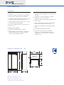
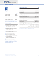
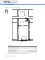
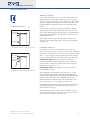
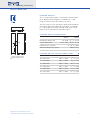
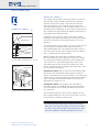
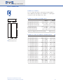
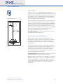
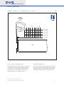
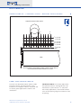
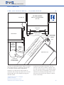
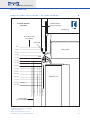
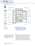
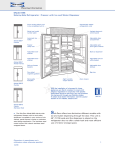
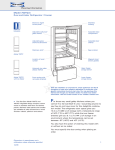
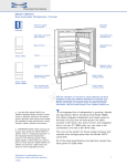
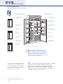
Planning Information
Built-In Model 642
Side-by-Side Refrigerator / Freezer
Front venting allows unit
to be completely built in
Hermetically sealed
refrigeration units
Serial and model
number plate
Lighted electronic
control panel
Adjustable dairy
compartment
Model 642/F
Framed
Model 642/O
Overlay
Adjustable wire
shelves
Adjustable roll-out
utility basket
Automatic ice
maker
Adjustable spillproof glass shelves
Ice storage
drawer
Egg tray
Roll-out freezer
baskets
Adjustable door
shelves
Four-sided
magnetic gaskets
High humidity
crisper drawer
Removable
kickplate
Door closers
(Stainless steel design shown)
Model 642/S (P/B)
Stainless Steel
The Sub-Zero Model 642 side-by-side
refrigerator / freezer is available in your
choice of the framed, overlay or stainless
steel design application. Three stainless
steel finishes are offered—classic (/S),
platinum (/P) and carbon (/B).
Dimensions in parentheses are in
millimeters unless otherwise specified.
11/06
With the installation of a harness kit, these
appliances are Star-K compliant to meet strict
religious regulations in conjunction with specific
instructions found on star-k.org. You may purchase
this harness kit through your Sub-Zero dealer.
To obtain local dealer information, visit the Locator
section of our website, subzero.com.
J
ust six inches bigger than the Model 661, the Model
642 satisfies the need for additional storage. This
midsize unit is one of the more popular Sub-Zero
models of the side-by-side configuration. Storage in the
doors and spacious interior seem to be everything a
customer could need in their home.
1
Planning Information
Built-In Model 642
F E AT U R E S
42" (1067) wide side-by-side refrigerator /
freezer
Framed, overlay and stainless steel applications provide complete design flexibility
Sub-Zero's dual refrigeration system ensures
the freshest food and energy efficiency
Shallow-depth design means access is easy
to any area of the refrigerator
Electronic digital controls are up front and
easy to use
Bright interior lighting
Adjustable, spill-proof glass shelves
High-humidity crisper drawer is large with
smooth sides for easy cleaning – there's
even an added storage drawer
Door alarm will let you know with an audible
beeping if your refrigerator or freezer door is
left ajar
Automatic ice maker provides an ample
supply of crescent-shaped ice
Solid core doors with magnetic gaskets and
door closers
Front venting allows unit to be completely
built in and serviced from the front
Meets strict Department of Energy requirements
UL approved for US and Canada
Two, five and twelve year residential
warranty – exclusions apply; warranty
information can be found on our website,
subzero.com
OVERALL DIMENSIONS
411/4"
(1048)
237/8"
3/8" (10)
FRAME EXTENSION
(606)
BEHIND
FRAME
84"
(2134)
259/16"
(649)
42"
(1067)
42"
24"
(1067)
(610)
Stainless steel design shown.
Dimensions may vary by ± 1/8" (3).
Dimensions in parentheses are in
millimeters unless otherwise specified.
2
Planning Information
Built-In Model 642
S P E C I F I C AT I O N S
Model 642
Side-by-Side Refrigerator / Freezer
Overall Width
42" (1067)
Overall Height
84" (2134)
Overall Depth
24" (610)
MODEL OPTIONS
Framed Design
642/F
Overlay Design
642/O
Classic Stainless Steel
642/S
Platinum Stainless Steel
642/P
Carbon Stainless Steel
642/B
You must allow 90 days from order to
delivery for platinum and carbon finishes.
ACCESSORIES
Refrigerator Capacity
16.2 cu ft (459 L)
Freezer Capacity
8.2 cu ft (232 L)
Minimum Height (levelers in)
25 9/16" (649)
Door Swing Clearance
Electrical Requirements
83" (2108)
115 V AC, 60 Hz, 15 amp circuit
1/ 4"
Plumbing Requirements
Water Supply
copper line
20–100 psi
Annual Energy Usage
(based on 9.06 cents per kilowatt hour)
650 kWh / $ 59
Louvered, panel or stainless steel
grilles in 1" (25) increments from
10" (254) to 15" (381) high
Shipping Weight
Framed – 541 lbs (245 kg)
Overlay – 541 lbs (245 kg)
Stainless Steel – 582 lbs (264 kg)
Front and grille panels for framed
design in white, almond and
classic stainless steel
Specifications are subject to change without notice.
Side panels in white, almond and
classic stainless steel
Extended framed handles
Stainless steel and polished
chrome handles for overlay design
Gallon door shelf
Dozen egg container with lid
90˚ and 105˚ door stop kits
Accessories are available through your
Sub-Zero dealer. To obtain local dealer
information, visit the Locator section of
our website, subzero.com.
Dimensions in parentheses are in
millimeters unless otherwise specified.
3
Planning Information
Built-In Model 642
I N S TA L L AT I O N S P E C I F I C AT I O N S
24" EXTEND WATER LINE
(610)
APPROX. 36" (914)
ROUGH FROM BACK WALL
OPENING
DEPTH
SHUT-OFF
VALVE
TOP VIEW
7"
E
(178)
6"
(152)
LOCATE ELECTRICAL
WITHIN SHADED AREA
411/2"
(1054)
ROUGH OPENING WIDTH
833/4"
751/2"
(2127)
ROUGH
OPENING
HEIGHT
WITH
STANDARD
11" (279)
GRILLE
(1918)
LOCATE WATER SUPPLY
WITHIN SHADED AREA
3"
(76)
18"
6"
(457)
(152)
W
FRONT VIEW
DIMENSIONS
Finished Rough Opening Width
41 1/2" (1054)
Finished Rough Opening Height
83 3/4" (2127)
Finished Rough Opening Depth
24" (610)
Location of Electrical
Within upper shaded area
Location of Water Supply
Within lower shaded area
See Installation Instructions shipped with unit for detailed specifications.
Refer to the Sub-Zero Design Guide pdf file for additional specifications.
Dimensions in parentheses are in
millimeters unless otherwise specified.
4
Planning Information
Built-In Model 642
I N S TA L L AT I O N N OT E S
Refer to the illustrations and specifications
for overall dimensions, finished rough opening
dimensions and installation specifics.
Allow the doors to open a minimum of 90˚ or
you'll have problems removing drawers. With
the doors opening at 90˚, you may have to
move drawers slightly to clear the door interior.
Refer to the minimum door swing clearances in
the specifications chart.
For corner installations, allow for a minimum
3" (76) filler so that the door can open to 90˚.
If you're using raised panels, consider using a
wider filler. A 90˚ door stop is available as an
accessory.
Be sure to add the filler strip width to your
finished rough opening dimension. In any sideby-side installation without a filler strip, add an
additional 1/2" (13) to your combined numbers.
This will allow for the proper width.
Refer to the full-scale illustrations at the end
of this section for specifics on door openings
and filler size alternatives.
If your client has chosen the stainless steel
design, the unit will be shipped complete with
wrapped stainless steel doors and handle
hardware. You will not have to install front
panels.
If your client has chosen the framed or
overlay design, you will be adding front panels
to give the unit the custom Sub-Zero look. The
overlay design also allows you to add your own
handles, or you may choose accessory handles
available through your Sub-Zero dealer. Refer to
pages 6–10 for detailed information on adding
panels.
For Built-In models with an automatic ice
maker, rough in the water supply line. Connect
a 1/4" OD copper line to the house supply, being
sure to use an easily accessible shut off valve
between the supply and the unit.
Do not use self-piercing valves. A saddle
valve kit (4200880) is available from your
Sub-Zero dealer. To obtain local dealer information, visit the Locator section of our website,
subzero.com.
Dimensions in parentheses are in
millimeters unless otherwise specified.
A line filter is required when water conditions have a high sediment content. The ice
maker operates on water pressure of 20 psi
(1.4 bar) to 100 psi (6.9 bar). In some cases a
reverse osmosis water filter system may not be
able to maintain the minimum water pressure
consistently.
The water line should be routed up through
the floor within 1/2" (13) from the back wall and
no higher than 3" (76) off the floor. If you have
to come through the wall, make sure the water
line is no more than 3" (76) from the floor.
Locate water supply within the shaded area
shown in the installation illustration.
Regardless of the routing, allow 3' (.9 m) of
excess copper tubing to remain outside the wall
or floor for easy connection to the unit.
A 115 volt, 60 Hz, 15 amp electrical supply
is required. The supply circuit for this appliance
must be protected by a 15 amp fuse or circuit
breaker. It is recommended that a separate
circuit, serving only this appliance, be provided.
All Built-In models are equipped with a 6'
(1.8 m) power supply cord with a 3-prong
grounding plug which must be plugged into a
mating 3-prong grounding type wall receptacle.
Locate electrical within the shaded area shown
in the installation illustration.
You must follow all National Electrical Code
regulations. In addition, be aware of local codes
and ordinances when installing your service.
To prevent the unit from tipping forward and
provide a stable installation, the unit must be
secured in place with an anti-tip blocking kit. If
there is a solid soffit above the unit with clearance between the unit and the soffit of 1" (25)
or less, you won't need to block the unit.
For installations with clearances of more
than 1" (25), you must block the unit with the
anti-tip blocking kit (wood block and hardware)
provided with each Built-In unit.
Refer to the Built-In Installation Instructions
packed with the appliance, which provides
step-by-step procedures for making sure the
unit is installed properly.
5
Planning Information
Built-In Model 642
A D D I N G PA N E L S
F R A M E D PA N E L S
PANELS 1/4" (6) THICK OR LESS
Trim reveal
1/4" (6) min
1/4" (6)
Panel
In your plan for panels, be sure you are working with the
Sub-Zero panel design family called for in your design. If
you have chosen the stainless steel design, the unit will be
shipped complete with wrapped stainless steel doors and
handle hardware. You will not have to install front door
panels.
If you and your client have ordered a framed or overlay
design model, you will be adding panels to give the unit
the custom Sub-Zero look. Specifications on the following
pages provide installation considerations for framed and
overlay door panels.
Side panels can be used with the framed, overlay and
stainless steel design applications. Refer to specifications
on page 10.
Framed door panel 1/4" (6) thick or less
F R A M E D PA N E L S
PANELS THICKER THAN 1/4" (6)
If the thickness of the custom panels is less than 1/4"
(6), they must be backed up with a sheet of shim material
to build the total thickness to 1/4" (6). If the panel is thicker
than 1/4" (6), an edge must be routed around the panel to
ensure a proper fit. Refer to the illustrations on this page.
Trim reveal
1/4" (6) min
Rout to 1/4" (6)
thickness
Framed door panel thicker than 1/4" (6)
IMPORTANT NOTE: Routing, recessing or optional
extended handles may be required on raised panels for
finger clearance under the handle. Refer to the full-scale
illustrations on pages 11–14.
IMPORTANT NOTE: The weight of each panel cannot
exceed 50 lbs (23 kg).
The traditional framed models come with an 11" (279)
louvered grille and elegant full-length handle. Optional
extended full-length handles that provide additional finger
clearance for raised panels are available through your
Sub-Zero dealer. To obtain local dealer information, visit
the Locator section of our website, subzero.com.
For framed door panel dimensions and dimensions for the
optional panel grille for the framed application, refer to
specifications on page 7.
To install framed panels, refer to the installation instructions shipped with each unit. These instructions can also
be found on our website, subzero.com.
Dimensions in parentheses are in
millimeters unless otherwise specified.
6
Planning Information
Built-In Model 642
F R A M E D PA N E L S
An 11" (279) louvered grille is standard on framed applications. Optional louvered grilles are available in 1" (25)
height increments from 10" (254) to 15" (381).
You may choose to use Sub-Zero's optional panel grille for
the framed application. Optional panel grilles are available
in 1" (25) height increments from 10" (254) to 15" (381).
Refer to the chart below for panel dimensions.
H
W
F R A M E D PA N E L D I M E N S I O N S
H
14" (356)
Refrigerator Door Panel
Freezer Door Panel
Handle Recess Location
WIDTH
HEIGHT
24" (610)
6711/16" (1719)
15 5/8" (397)
6711/16" (1719)
A – 38 5/32" (969)
A
Maximum Weight (per panel)
W
W
Framed Door Panels
Framed Grille Panel
Dimensions in parentheses are in
millimeters unless otherwise specified.
50 lbs (23 kg)
F R A M E D G R I L L E PA N E L D I M E N S I O N S
WIDTH
HEIGHT
10" (254) Grille
40 3/16" (1021)
8 15/16" (227)
11" (279) Grille
40 3/16" (1021)
9 15/16" (252)
12" (305) Grille
40 3/16" (1021)
10 15/16" (278)
13" (330) Grille
40 3/16" (1021)
1115/16" (303)
14" (356) Grille
40 3/16" (1021)
12 15/16" (329)
15" (381) Grille
40 3/16" (1021)
13 15/16" (354)
7
Planning Information
Built-In Model 642
O V E R L AY PA N E L S
O V E R L AY PA N E L S
The overlay design allows decorative panels to cover the
door trim for a more seamless appearance that blends
with the design of the room. To achieve this look, the
most common way is to work with three panels—the
decorative overlay panel, a .10" (3) spacer panel and a 1/4"
(6) backer panel. Depending on your cabinet manufacturer,
this could be one panel routed for different dimensions or
more likely, three different panels.
Spacer Panel
.10"
Overlay Panel
(3)
1/4" (6) Backer
5/16" (8) min
5/32" (4)
1/16" (2)
Panel
Door/Drawer/
Grille Trim
Three panel assembly—cross section
Overlay Panel
Spacer Panel
Regardless of the physical construction of the panels
(routing or three panel assembly), you will need to follow
the exact dimensions and panel placement to ensure a
proper fit.
The top illustration on this page is a cross section view of
the three panel assembly showing placement of the
door / drawer / grille trim. The bottom illustration shows a
rear view of the three panel assembly and critical dimensions, standard for all overlay models.
Overlay models will come with no handle hardware,
because the beauty of this design is that you can match
the surrounding cabinetry hardware. These models will
come with an 11" (279) panel grille which will accept
decorative panel inserts to match the look of the door
panels. For overlay door and grille panel dimensions, refer
to specifications on page 9.
IMPORTANT NOTE: Keep in mind that the Sub-Zero door
panels have the potential for hitting adjacent cabinets
and/or countertops when they are opened. You need to be
aware of your surrounding cabinetry and space limitations
when using the overlay models. Refer to the full-scale
illustrations on pages 13–14.
Backer
Panel
~3/4"
(19)
.10" (3)
1/4" (6)
IMPORTANT NOTE: The weight of each door panel
assembly cannot exceed 50 lbs (23 kg). The total thickness of all panels for an overlay model must be at least
5/8" (16) thick.
Three panel assembly—rear view
To install overlay panels, refer to the installation instructions shipped with each unit. These instructions can also
be found on our website, subzero.com.
Do not exceed the dimensions listed for the overlay
grille panel. The decorative panel cannot be any larger
or it may restrict the air flow to the compressor area
and cause problems with the operation of the unit.
Dimensions in parentheses are in
millimeters unless otherwise specified.
8
Planning Information
Built-In Model 642
O V E R L AY PA N E L S
An 11" (279) panel grille is standard on overlay applications. Optional panel grilles are available in 1" (25) height
increments from 10" (254) to 15" (381).
O V E R L AY PA N E L D I M E N S I O N S
H
WIDTH
W
Refrigerator Door Panel
Refrigerator Door Spacer
Refrigerator Door Backer
H
Freezer Door Panel
Freezer Door Spacer
Freezer Door Backer
24 5/16"
HEIGHT
23 3/8" (594)
24" (610)
68" (1727)
67 1/16" (1703)
6711/16" (1719)
1515/16" (405)
15" (381)
15 5/8" (397)
68" (1727)
67 1/16" (1703)
6711/16" (1719)
(618)
Maximum Weight (per panel assembly)
50 lbs (23 kg)
O V E R L AY G R I L L E PA N E L D I M E N S I O N S
WIDTH
W
W
Overlay Door Panels
Overlay Grille Panel
Dimensions in parentheses are in
millimeters unless otherwise specified.
HEIGHT
10" (254) Grille Panel
10" (254) Grille Spacer
10" (254) Grille Backer
40 7/16"
39 1/2" (1003)
40 1/8" (1019)
8 5/16" (211)
8 15/16" (227)
11" (279) Grille Panel
11" (279) Grille Spacer
11" (279) Grille Backer
40 7/16" (1027)
39 1/2" (1003)
40 1/8" (1019)
10 1/4" (260)
9 5/16" (237)
9 15/16" (252)
12" (305) Grille Panel
12" (305) Grille Spacer
12" (305) Grille Backer
40 7/16" (1027)
39 1/2" (1003)
40 1/8" (1019)
11 1/4" (286)
10 5/16" (262)
10 15/16" (278)
13" (330) Grille Panel
13" (330) Grille Spacer
13" (330) Grille Backer
40 7/16" (1027)
39 1/2" (1003)
40 1/8" (1019)
12 1/4" (311)
11 5/16" (287)
11 15/16" (303)
14" (356) Grille Panel
14" (356) Grille Spacer
14" (356) Grille Backer
40 7/16" (1027)
39 1/2" (1003)
40 1/8" (1019)
13 1/4" (337)
12 5/16" (313)
12 15/16" (329)
15" (381) Grille Panel
15" (381) Grille Spacer
15" (381) Grille Backer
40 7/16" (1027)
39 1/2" (1003)
40 1/8" (1019)
14 1/4" (362)
13 5/16" (338)
13 15/16" (354)
(1027)
9 1/ 4"
(235)
9
Planning Information
Built-In Model 642
S I D E PA N E L S
Side panels can be used with the framed, overlay and
stainless steel design applications. When planning for side
panels with the installation of the Built-In model, you need
to be aware of space configuration to achieve a pleasing
fit. Depending on the exact panel you are using with your
unit, the height of the panel will vary.
S I D E PA N E L S
13 1/4" (337)
1
1/4" (6)
23 7/8" (606)
BEHIND FRAME
Cut-outs around the toe kick and grille area are required if
a 1/4" (6) thick panel will be inserted into the main frame
channel. The panel will need to be 24" (610) deep. Refer to
the illustration on this page for placement of toe kick and
grille area cut-outs. If a 3/8" (10) thick panel is used, the
panel will abut the main frame and should be 23 7/8" (606)
deep. The toe kick area may or may not be cut out
depending on the look you want to achieve.
IMPORTANT NOTE: The use of side panels may change
the width of your rough opening.
H A R DWA R E C O N S I D E R AT I O N S
1/4" (6)
3" (76)
4" (102)
3" (76)
Cut-outs for grille and toe kick area
Overlay models come without handle hardware. The
beauty of this design is that you can match the surrounding cabinet hardware. You or the cabinet manufacturer
must provide handle hardware to match the overall decorating scheme.
The handle hardware must be installed before installing
the panel assembly. Use larger D-style handles. If screws
with thick heads are used, the screws will need to be
countersunk into the door before the panel is put into
place. Refer to the full-scale illustrations on pages 11–12
for handle hardware considerations.
IMPORTANT NOTE: Sub-Zero does not recommend using
single pull knobs on any of its Built-In models.
Optional stainless steel handles are available in a variety of
diameters and lengths in the classic, platinum and carbon
stainless steel finishes and polished chrome. Contact
your Sub-Zero dealer for specifics. To obtain local dealer
information, visit the Locator section of our website,
subzero.com.
Dimensions in parentheses are in
millimeters unless otherwise specified.
10
Planning Information
Built-In Model 642
H A N D L E P R O F I L E – F R A M E D A P P L I C AT I O N
OPTIONAL
EXTENDED
FULL-LENGTH
HANDLE
1"
2"
3"
(25)
(51)
(76)
11/4"(32) PANEL
STANDARD
FULL-LENGTH
HANDLE
1"(25) PANEL
3/4"(19) PANEL
1/2"(13) PANEL
1/4"(6) PANEL
1/4"(6) FRAMED PANEL
DOOR
F U L L - S C A L E T E M P L AT E S
HANDLE PROFILE
The following full-scale illustrations enable you
to understand some of the unique situations
you may face as you design the Built-In units
into homes. These templates can be easily
photocopied or used in your tracings.
The full-scale illustration above shows handle
placement for the framed application standard
full-length handle and the optional extended
full-length handle shown in the dashed line.
Dimensions in parentheses are in
millimeters unless otherwise specified.
11
Planning Information
Built-In Model 642
H A N D L E P R O F I L E – S T A I N L E S S S T E E L / O V E R L AY A P P L I C A T I O N S
STANDARD STAINLESS STEEL HANDLE
1"
2"
3"
(51)
(76)
11/4" (32) PANEL
1" (25) PANEL
3/4" (19) PANEL
5/8" (16) PANEL
1/2" (13) PANEL
1/4" (6) PANEL
1/4" (6) APPROXIMATE THICKNESS OF WRAPPED STAINLESS STEEL DOOR
DOOR
NOTE: FOR OVERLAY APPLICATIONS, OPTIONAL STAINLESS STEEL HANDLE
MUST BE MOUNTED ON PANEL MINIMUM 5/8" (16) THICK.
PA N E L A N D H A N D L E P R O F I L E
The full-scale illustration above shows handle
placement for the standard stainless steel
handle on the wrapped stainless steel door and
on overlay panel applications shown in the
dashed line.
Dimensions in parentheses are in
millimeters unless otherwise specified.
IMPORTANT NOTE: For overlay applications,
the optional stainless steel handle must be
mounted on a panel at least 5/8" (16) thick.
For overlay applications, mount door handles
close to the opening edge of the door for ease
of opening.
12
Planning Information
Built-In Model 642
PA N E L A N D H A N D L E P R O F I L E – 1 3 0 ˚ D O O R O P E N I N G
130˚ DOOR OPENING
WITH 2" (51) FILLER STRIP
SUB-ZERO UNIT
SUB-ZERO UNIT
(TOP VIEW)
FILLER STRIP
2" (51)
ALLOW FOR FILLER LAP
BEHIND FLANGE
DOOR CLOSED
OVERLAY PANEL
3/4" (19) THICK
(NOMINAL)
MAIN FRAME
HINGE
)P
AN
3)
*1
/4"
1
(6
/2"
(1
3
DOOR OPEN @ 130˚
EL
9)
(1
/4"
PA
NE
L
(2
PA
N
EL
PA
N
5)
(3
1"
11
/4"
EL
PA
N
EL
STANDARD
FRAMED
FULL-LENGTH
HANDLE
2)
APPROX
PROFILE OF
STAINLESS
STEEL DOOR
AND HANDLE
OPTIONAL
FRAMED EXTENDED
FULL-LENGTH HANDLE
The full-scale illustration above shows the panel
and handle profile of a 130˚ door opening with
2" (51) filler strip for framed applications.
Interference of door panels with handles at
maximum door swing may require the use of an
optional 90˚ door stop available through your
Sub-Zero dealer.
To obtain local dealer information, visit the
Locator section of our website, subzero.com.
The full-scale illustration on the following page
lets you see what considerations you need to
make for any overlay panel applications, and
how they may interact with adjacent cabinets
and/or countertops.
*Approximate thickness of wrapped
stainless steel door.
Dimensions in parentheses are in
millimeters unless otherwise specified.
13
Planning Information
Built-In Model 642
O V E R L AY PA N E L A P P L I C A T I O N – 9 0 ˚ D O O R O P E N I N G
90˚ DOOR OPENING
(TOP VIEW)
NOMINAL OVERALL
WIDTH OF SUB-ZERO
SUB-ZERO UNIT
237/8" (606) TO REAR
OF SUB-ZERO
MAIN FRAME
0" (0)
1/4" (6)
DOOR CLOSED
1/2" (25)
3/4" (19)
HINGE
1" (25)
11/4" (32)
11/2" (38)
13/4" (44)
2" (51)
21/4" (57)
21/2" (63)
DOOR OPEN @ 90˚
23/4" (70)
3" (76)
31/4" (83)
*1/4" (6) PANEL
1/2" (13) PANEL
3/4" (19) PANEL
1" (25) PANEL
11/4" (32) PANEL
31/2" (89)
OVERLAY PANEL
3/4" (19) THICK (NOMINAL)
*Approximate thickness of wrapped
stainless steel door.
Dimensions in parentheses are in
millimeters unless otherwise specified.
14