1
SENSAIRE® SERIES – MODEL
MHS120L MOTION/HUMIDITY
SENSING FAN/LIGHT/NIGHT
LIGHT
READ AND SAVE
THESE INSTRUCTIONS
SERIE SENSAIRE® – MODELO
MHS120L VENTILADOR/LUZ/LUZ
NOCTURNA CON SENSORES DE
MOVIMIENTO Y HUMEDAD
®
LEA Y CONSERVE
ESTAS INSTRUCCIONES
WARNING
ADVERTENCIA
TO REDUCE THE RISK OF FIRE, ELECTRIC SHOCK,
OR INJURY TO PERSONS, OBSERVE THE FOLLOWING:
PARA REDUCIR EL RIESGO DE INCENDIO, DESCARGA
ELECTRICA, O LESIONES PERSONALES, CUMPLA CON
LOS SIGUIENTES PUNTOS:
1. Use this unit only in the manner intended by the
manufacturer. If you have questions, contact the
manufacturer at the address or telephone number
listed in the warranty.
2. Before servicing or cleaning unit, switch power off
at service panel and lock the service disconnecting
means to prevent power from being switched on
accidentally. When the service disconnecting means
cannot be locked, securely fasten a prominent warning device, such as a tag, to the service panel.
3. Installation work and electrical wiring must be done
by a qualified person(s) in accordance with all applicable codes and standards, including fire-rated
construction codes and standards.
4. Sufficient air is needed for proper combustion and exhausting of gases through the flue (chimney) of fuel
burning equipment to prevent backdrafting. Follow the
heating equipment manufacturer’s guideline and
safety standards such as those published by the National Fire Protection Association (NFPA), and the
American Society for Heating, Refrigeration and Air
Conditioning Engineers (ASHRAE), and the local code
authorities.
5. When cutting or drilling into wall or ceiling, do not
damage electrical wiring and other hidden utilities.
6. Ducted fans must always be vented to outdoors.
7. This unit may be used over a tub or shower enclosure when installed in a GFCI protected branch circuit (ceiling installation only).
8. If this unit is to be installed over a tub or shower, it
must be marked as appropriate for the application.
9. Never place a switch where it can be reached from
a tub or shower.
10. Do not use this unit with any solid-state speed control device.
11. This unit must be grounded.
1. Solamente use esta unidad de la manera propuesta
por el fabricante. Si tiene alguna pregunta, póngase
en contacto con el fabricante en la dirección o
teléfono anotados en la garantía.
2. Antes de limpiar o de poner en servicio la unidad,
apague el interruptor en el panel de servicio, y
asegure el panel de servicio para evitar que se
encienda accidentalmente. Cuando el dispositivo
para desconectar el servicio eléctrico no puede
ser cerrado con algún tipo de traba, sujete
fuertemente al panel de servicio, una etiqueta de
advertencia prominente.
3. El trabajo de instalación y el cableado eléctrico
deben de llevarse a cabo por personal calificado
de acuerdo con todos los códigos y las normas
aplicables, incluyendo los códigos y normas de
construcción contra incendios.
4. Se requiere una cantidad de aire suficiente para la
combustión de gases por la chimenea del equipo
que quema combustible para evitar retrogresión de
la llama. Siga las especificaciones y estándares de
seguridad para equipos de calefacción del
fabricante, tales como los publicados por la
Asociación Nacional de Protección Contra
Incendios (NFPA por sus siglas en inglés), y la
Sociedad Americana de Ingenieros de Calefacción,
Refrigeración y Aire Acondicionado (ASHRAE), y
los códigos de las autoridades locales.
5. Cuando corte o taladre en una pared o cielo raso,
no dañe los cables eléctricos u otras instalaciones
no visibles.
6. Los ventiladores con conductos deben siempre
extraer hacia el exterior.
7. Esta unidad puede ser usada sobre una bañera o
ducha cuando esté instalada con un circuito
protector desviador a tierra en caso de corto circuito
(GFCI) (solamente instalación del cielo raso).
8. Si esta unidad va a ser instalada sobre una bañera
o ducha, debe ser marcada como apropiada para
esta aplicación.
9. Nunca coloque un interruptor donde pueda ser
alcanzado desde una bañera o ducha.
10. No use esta unidad con aparatos de estado sólido
de control de velocidad.
11. Esta unidad debe ser conectada a tierra.
CAUTION
1. For general ventilating use only. Do not use to exhaust hazardous or explosive materials and vapors.
2. This product is designed for installation in flat ceilings only. DO NOT MOUNT THIS PRODUCT IN A
WALL.
3. To avoid motor bearing damage and noisy and/or
unbalanced impellers, keep drywall spray, construction dust, etc. off power unit.
4. Please read specification label on product for further information and requirements.
PRECAUCION
1. Solamente para uso de ventilación general. No se
use para extraer materiales o vapores peligrosos o
explosivos.
2. Este producto está diseñado solamente para
instalarse en los techos planos. NO MONTE ESTE
PRODUCTO EN LA PARED.
3. Para evitar daños al cojinete del motor y/o
impuldores ruidosos o desequilibrados, mantenga
la fuente de potencia lejos de rocíos de pared de
yeso, de polvo de construcción, etc.
4. Lea la etiqueta de especificaciones del producto
para más información y requisitos.
INSTALLER: Leave This Manual With The Homeowner. HOMEOWNER: Use and Care Information on Pages 5 & 6.
INSTALADOR: Deje este manual con el dueño de casa. DUEÑO DE CASA: Información del uso y mantenimientoen la páginas 5 y 6.
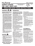
PLAN THE
INSTALLATION
1. Choose the installation location.
The location of your SENSAIRE® fan is very important.
Follow these guidelines for best operation.
Humidity sensing guidelines
a. The SENSAIRE® fan uses a humidity sensor that responds to both increases in humidity and to high humidity. The humidity sensor may turn the fan ON when
environmental conditions change. If the fan continuously responds to changing environmental conditions,
"SENSITIVITY" adjustment may be required.
b. Locate unit above (GFCI protected circuit required)
or within 5 feet of shower head.
c. Locate unit away from heating or cooling sources
which can affect humidity levels.
d. Locate unit only on flat ceilings up to 12 feet high for
proper sensing.
e. Unit must be installed in ceiling to properly sense
moisture.
f. Do not locate near window. Unit may respond to the
outdoor humidity level.
Motion sensing guidelines
a. Unit will respond to movement by people and animals.
After the unit stops sensing movement, it will stay ON
for an additional 20 minutes (approx.). The length of
ON time can be adjusted from approx. 5 to 60 minutes.
b. The sensor’s viewing area is cone-shaped with a diameter of approximately 11 ft. at floor level in an 8 ft.
high room. The viewing area can be reduced to accommodate your installation.
c. Refer to “USE AND CARE” section on pages 5 & 6 for
details about adjusting the time and the viewing area.
d. Locate unit away from hallways and other high traffic
areas to prevent unwanted start-ups.
e. Locate unit only on flat ceilings up to 12 feet high for
proper sensing.
f. Locate unit in normal traffic flow. Unit will not sense
motion in remote areas of room.
Ducting guidelines
The fan will operate most efficiently when located where
the shortest possible duct run and minimum number of
elbows will be needed.
2. Plan the wiring.
Plan to supply the unit with proper line voltage and appropriate power cable. Power cable should be routed to
the switch box first and then to the unit (See Figs. 9 &
10).
Do not control this unit with a speed control. Damage to
the sensor unit will result.
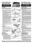
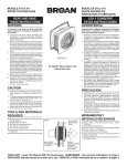
Follow these basic steps when installing this unit:
• Nail housing to joists.
• Attach ductwork.
• Connect power cable.
• Install fan assembly.
• Fasten grille to housing.
FIG. 1
POWER
CABLE
CEILING
CABLE DE
JOIST
POTENCIA
VIGA DEL
TECHO
MOUNTING
BRACKET
HOUSING SOPORTE DE
CAJA
MONTAJE
DRYWALL
PARED DE
YESO
GRILLE
REJILLA
2
PLANIFICACION DE
LA INSTALACION
1. Elija la posición de instalación
La posición de su ventilador SENSAIRE ® es muy
importante. Siga estas instrucciones para un mejor
funcionamiento:
Instrucciones para el sensor de humedad
a. El ventilador SENSAIRE® usa un sensor de humedad
que reacciona a aumentos de humedad y a humedad
alta. El sensor de humedad puede activar el
ventilador (ON) en ocasiones cuando hay combios
medioambientales. Si el ventilador responde
continuamente a condiciones medio-ambientales
combiantes, se puede necesitar ajustar la
sensibilidad (SENSITIVITY).
b. Coloque la unidad (se necesita un circuito protector
desviador a tierra en caso de corto circuito (GFCI)) a
1,52 m o más (5 pies o más) de la ducha.
c. Coloque la unidad alejada de fuentes de calor o frio
que puedan afectar los niveles de humedad.
d. Coloque la unidad solamente en cielos rasos planos
de hasta 3,66 m (12 pies) de alto para una detección
apropiada.
e. La unidad debe ser instalada en el cielo raso para
detectar humedad de manera apropiada.
f. No coloque la unidad cerca de una ventana. La
unidad puede responder al nivel de humedad exterior.
Instrucciones para el sensor de movimiento
a. La unidad responderá al movimiento de personas y
animales. Después que la unidad deja de detectar
movimiento, continuará ENCENDIDA durante unos
20 minutos aproximadamente. La duración del tiempo
en que la unidad permanece encendida se puede
regular de 5 hasta 60 minutos (aproximadamente).
b. El área de detección del sensor tiene forma de cono
con un diámetro de aproximadamente 3,35 m (11
pies) al nivel del suelo en una habitación de 2,44 m
(8 pies). El área de detección se puede reducir para
que calce en su instalación.
c. Haga referencia a la sección de “USO Y
MANTENIMIENTO” de la páginas 5 y 6 para detalles
sobre cómo ajustar el tiempo y el área de detección.
d. Sitúe la unidad alejada de pasillos y otras áreas de
alto tráfico para evitar arranques indeseados.
e. Coloque la unidad solamente en cielo rasos planos
de hasta 3,66 m (12 pies) de alto para una detección
apropiada.
f. Sitúe la unidad en flujo normal de tráfico. La unidad
no detectará movimiento en un área remota de la
habitación.
Instrucciones para el tendido de conductos
El ventilador funcionará de la forma más eficiente
cuando se sitúe donde se necesite el mínimo número
de conductos y el menor número posible de codos.
2. Planificación del cableado eléctrico
Planifique suministrar a la unidad el voltaje de línea y el
cable de potencia apropiados. El cable de potencia debe
llevarse primero a la caja de interruptores y luego a la
unidad (Vea Figs. 9 y 10).
No controle esta unidad con un control de velocidad.
Esto resultará en daños a la unidad del sensor.
Siga los siguientes pasos básicos cuando instale esta
unidad:
• Clave la caja a las vigas o soportes.
• Fije los conductos
• Conecte el cable de potencia
• Instale el conjunto del ventilador
• Fije la rejilla a la caja
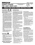
PREPARE THE FAN
FIG. 2
CAPTIVE SCREW
TORNILLO CAUTIVO
1. Disengage the captive screw holding the fan assembly in place. Lift assembly from housing. (FIG. 2)
2. Choose either the top or side of housing for electrical connection. Remove the knockout by bending it
back and forth to break tabs. (FIG. 3)
3. Slide adjustable mounting brackets into bracket
channels on housing. NOTE: Housing may be
mounted directly to joist using holes and slots provided. Use brackets for additional support. (FIG. 4)
1. Desune el tornillo cautivo que sujeta el conjunto
del ventilador en su sitio. Saque el conjunto de su
caja. (FIG. 2)
2. Elija la parte lateral o la parte superior de la caja
para hacer las conexiones eléctricas. Saque el
disco removible doblando éste para adelante y para
atrás y así romper las lengüetas. (FIG. 3)
3. Deslice los soportes ajustables de montaje en los
canales para soporte de la caja. NOTA: La caja se
puede montar directamente a la viga usando los
agujeros y las ranuras que se incluyen. Use los
soportes para apoyo adicional. (FIG. 4)
INSTALL THE FAN
1. Choose the location for your fan. For best possible
performance, use the shortest possible duct run and
a minimum number of elbows.
2. Position unit between joists and extend mounting
brackets. Position brackets such that bottom edge
of housing will be flush with finished ceiling. Mark
the top of keyhole slot on all four mounting brackets. (FIG. 5)
3. Remove unit temporarily, and pound nails partially
into joists at all four marked locations. (FIG. 6)
4. Hang unit from nails. Use measuring guides on corners of housing to check if unit will be flush with finished ceiling. Pound nails tight. For wide joist centers: A #8 x 3/8 self-tapping screw can be used to
join extended brackets together and create a rigid
mount. To ensure a noise-free mount, crimp the
bracket channels tightly around mounting brackets.
(FIG. 7)
5. Snap the damper/duct connector onto housing.
Make sure that tabs on the connector lock in housing slots and that gravity closes damper. (FIG. 8)
6. Install 4” round duct and extend duct to outside
through a roof or wall cap. Check damper to make
sure that it opens freely. Tape all duct connections
to make them secure and air tight.
PREPARACION DEL
VENTILADOR
FIG. 3
INSTALACION DEL
VENTILADOR
1. Elija la posición del ventilador. Para asegurar el
mayor rendimiento, use el mínimo número posible
de conductos y el mínimo de codos.
2. Coloque la unidad entre las vigas y extienda los
soportes de montaje. Sitúe los soportes de manera
que el extremo inferior de la caja esté a nivel con el
cielo raso acabado. Marque la parte superior de la
ranura en los cuatro soportes de montaje. (FIG. 5)
3. Saque la unidad por unos momentos, y clave los
clavos parcialmente en las vigas en las cuatro
posiciones marcadas. (FIG. 6)
4. Cuelgue la unidad en los clavos. Use las guías de
medida en las esquinas de la caja para comprobar
si la unidad está a nivel con el cielo raso acabado.
Clave los clavos completamente. Si existen centros
de viga anchos: se puede usar un tornillo
autoenroscable #8 x 3/8 para unir los soportes
extendidos y crear una superficie de montaje rígida.
Para asegurar un montaje sin ruidos, doble los
canales de los soportes fuertemente alrededor de
los soportes de montaje. (FIG. 7)
5. Conecte el conector del amortiguador/conducto a
la caja. Compruebe que las lengüetas en el
conector cierran en las ranuras de la caja y que el
amortiguador cierra por gravedad. (FIG. 8)
6. Instale conducto redondo de 4 pulg. y extienda el
conducto hacia el exterior a través de la cubierta
del cielo raso o la pared. compruebe que el
amortiguador abre con libertad. Cubra con cinta
adhesiva todas las conexiones de conductos para
hacerlas seguras y herméticas.
FIG. 4
FIG. 5
FIG. 6
FIG. 7
FIG. 8
3
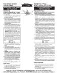
1. The two most common methods
of wiring this fan are shown in Figures 9 & 10. Follow the one you
chose when you planned the installation.
NOTE: An extra deep singleganged and/or double-ganged
box is usually required. Check
code requirements.
2. Remove wiring cover. Run electrical cable as directly as possible
to unit. Do not allow cable to
touch sides or top of unit after installation is complete. Push all
wiring into corner of unit. Replace
wiring cover.
3. Replace fan assembly and secure with captive screw.
4. Plug wiring connectors into their
receptacles.
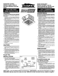
WIRING OPTION #1
FIG. 9
Allows fan to operate in automatic mode or manual on with timed off mode
(for odor control) by cycling ON/OFF switch. Allows fan circuit to be turned
OFF when desired.
OPCIÓN DE CONEXIÓN #1
Permite que el ventilador funcione automática o manualmente con el
temporizador apagado (para controlar los olores) reciclando el interruptor
(ON/OFF). Permite apagar (OFF) el circuito del ventilador si se desea.
MODEL / MODELO 66V/66W, P66V/P66W
3-FUNCTION CONTROL (PURCHASE SEPARATELY)
CONTROL DE 3 FUNCIONES (COMPRESE POR SEPARADO)
LIGHT (AUTO/OFF)
LUZ
(AUTOMATICO/
APAGAGO)
BLK
NEG
COM
NIGHT LIGHT
(ON/OFF)
LUZ NOCTURNA
(ENCENDIDO/
APAGADO)
BLU
AZL MOTION SENSOR
SENSOR DE
MOVIMIENTO
WHT*
BLC*
ORG / NRJ
BLK
NEG
FAN (AUTO/OFF)
VENTILADOR
(AUTOMATICO/
APAGADO
120VAC BLK / NEG
LINE IN
LINEA DE WHT / BLC
ENTRADA
120 VCA GRD / TRA
LIGHT / LUZ
NIGHT LIGHT
LUZ NOCTURNA
RED / ROJ
FAN
VENTILADOR
BLK / NEG
WIRE THE FAN
WHT
BLC
HUMIDITY SENSOR
SENSOR DE
HUMIDIDAD
WHT / BLC
WHT / BLC
GRD
TRA
SWITCH BOX / CAJA DE INTERRUPTORES
UNIT / UNIDAD
* CODE REQUIRES BOTH ENDS OF THIS WIRE'S INSULATION TO BE COLORED BLACK, SINCE IT IS SWITCHED.
USE A FELT-TIPPED MARKER.
* EL CODIGO REQUIERE QUE AMBOS EXTREMOS DEL AISLAMIENTO DE ESTE CABLE SEAN DE COLOR NEGRO YA
QUE ES CONMUTADO. USE UN LAPIZ COLORANTE.
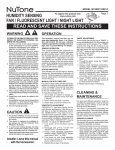
FIG. 10
WIRING OPTION #2
Fan can be turn ON, OFF, or set to operate automatically.
OPCIÓN DE CONEXIÓN #2
El ventilador se puede encender, apagar, o poner en función automáticamente.
MODEL / MODELO 77DV, 77DW, P77DV, P77DW
4-FUNCTION CONTROL (PURCHASE SEPARATELY)
CONTROL DE 4 FUNCIONES (COMPRESE POR SEPARADO)
FAN - ON/OFF/AUTO
VENTILADOR ENCENDIDO/
APAGADO/
AUTOMATICO
BLK / NEG
BLK / NEG
120VAC
LINE IN
WHT / BLC
LINEA DE
ENTRADA
120 VCA GRD / TRA
BLK
NEG
BLU
AZL
WHT*
BLC*
BLK HUMIDITY SENSOR
SENSOR DE
NEG
MOVIMIENTO
FAN
VENTILADOR
RED / ROJ
COM
NIGHT LIGHT - ON/OFF
LUZ NOCTURNA ENCENDIDO/APAGADO
LIGHT - AUTO/OFF
LUZ AUTOMATICO/APAGADO
RED
ROJ
BLK
NEG
ORG / NRJ
RED
ROJ
BLU
AZL MOTION SENSOR
SENSOR DE
HUMIDIDAD
COM
BLK
NEG
WHT
BLC
GRD
TRA
SWITCH BOX / CAJA DE INTERRUPTORES
NIGHT LIGHT
LUZ NOCTURNA
LIGHT / LUZ
WHT
BLC
WHT / BLC
UNIT / UNIDAD
* CODE REQUIRES BOTH ENDS OF THIS WIRE'S INSULATION TO BE COLORED BLACK, SINCE IT IS SWITCHED.
USE A FELT-TIPPED MARKER.
* EL CODIGO REQUIERE QUE AMBOS EXTREMOS DEL AISLAMIENTO DE ESTE CABLE SEAN DE COLOR NEGRO YA
QUE ES CONMUTADO. USE UN LAPIZ COLORANTE.
4
CABLEADO
ELECTRICO DEL
VENTILADOR
1. Los dos métodos más comunes
de conectar este ventilador se
muestran en las Figuras 9 y 10.
Siga el que haya elegido cuando
planeó la instalación.
NOTA:
Normalmente
se
necesita
una
caja
extra-profunda de acople
sencillo o doble. Compruebe
los requisitos de código.
2. Saque la cubierta de la caja de
cables y conecte la unidad
siguiendo el diagrama. Lleve el
cable eléctrico de la forma más
directa posible a la unidad. No
permita que el cable toque los
lados o la parte superior de la
unidad después que la instalación
se haya completado. Empuje
todos los cables hacia una
esquina de la unidad. Coloque de
nuevo la cubierta de la caja de
cables.
3. Coloque de nuevo el conjunto del
ventilador y a segure éste con el
tornillo cautivo.
4. Enchufe los conectores en sus
enchufes.
ATTACH GRILLE
SUJECCION DE LA
REJILLA
FIG. 11
1. Plug motion sensor wiring into motion control assembly.
2. Plug light/night light wiring into humidity control assembly.
3. Attach grille assembly with (2) phillips-head screws,
provided. DO NOT OVERTIGHTEN - Damage to
grille may result. (FIG. 11)
4. Remove lens by gently pulling on one edge. (FIG.
12)
5. Install bulbs. Primary - 100W Max. Night Light - 7
W, Type C7.
1. Enchufe el cableado de sensor de movimiento en
conjunto de control de movimiento.
2. Enchufe el cableado de la luz/luz nocturna en
conjunto de control de humidad.
3. Fije el conjunto de la rejilla con dos tornillos de rosca
phillips que se incluyen. NO LOS SOBREAPRIETE
- Esto puede resultar en daños a la rejilla. (FIG. 11)
4. Saque el lente empujando suavemente de un
extremo. (FIG. 12)
5. Instale las bombillas. Luz primaria: 100 vatios Max.
Luz nocturna 7 vatios, tipo C7.
FIG. 12
USE AND CARE
USO Y MANTENIMIENTO
WARNING
ADVERTENCIA
ANTES DE LIMPIAR, AJUSTAR O SERVIR LA UNIDAD, CORTE LA
CORRIENTE ELÉCTRICA EN EL PANEL DE SERVICIO. BLOQUEE EL PANEL
DE SERVICIO PARA EVITAR QUE LA FUERZA ELÉCTRICA SE RECONECTE
ACCIDENTALMENTE.
BEFORE CLEANING, SERVICING OR ADJUSTING THE UNIT, SWITCH
POWER OFF AT SERVICE PANEL. LOCK SERVICE PANEL TO PREVENT
POWER FROM BEING SWITCHED ON ACCIDENTALLY.
THERMOSTAT & SENSOR OPERATION
OPERACIÓN del TERMOSTATO y SENSOR
Un termostato es parte integrante del conjunto SENSAIRE® de ventilador con
luces diurna y nocturna para asegurar el funcionamiento correcto del sensor. El
ventilador puede prenderse (ON) (si estuvo apagado) (OFF) si la luz queda
prendida (ON) por largo tiempo.
La unidad lleva un sensor de humedad de gran refinamiento técnico que responde a: (a) de rápidos a moderados aumentos de la humedad (regulables por
el usuario) o (b) humedad que excede el punto fijado por el usuario (50% - 100%
Humedad Relativa). El sensor de humedad puede en ocasiones activar el
ventilador (ON) cuando ocurren cambios medioambientales. Si el ventilador responde continuamente a condiciones medioambientales cambiantes puede ser
necesario ajustar la sensibilidad (SENSITIVITY).
A thermostat is built into the SENSAIRE® fan/light/night light to assure proper sensor operation. The fan may turn ON (if it was OFF) if the light is ON for an extended period of time.
The unit uses a sophisticated humidity sensor that responds to: (a) rapid to moderate (user-adjustable) increases in humidity or (b) humidity above a user-adjustable set-point (50%-100% Relative Humidity). The humidity sensor may occasionally turn the fan ON when environmental conditions change. If the fan continuously responds to changing environmental conditions, "SENSITIVITY" adjustment may be required.
MANUAL ON WITH TIMED OFF (Fan)
The SENSAIRE® fan/light/night light has an additional operation feature. For odor
or vapor control, the fan can be energized by cycling the power switch. Once the
fan has been energized in this manner, it will remain on for the user-adjustable
"TIMER" period (approx. 5 to 60 minutes). This period is factory-set for approximately 20 minutes.
To manually energize the fan:
1. If fan power switch is already ON, proceed to Step 2; otherwise, turn power
switch ON for more than 1 second.
2. Turn fan power switch OFF for less than 1 second.
3. Turn fan power switch back ON and fan will turn ON.
ENCENDIDO MANUAL (ON) CON TEMPORIZADOR APAGADO (OFF)
(VENTILADOR)
El ventilador con luces diurna y nocturna SENSAIRE® tiene una característica de
funcionamiento adicional. Para controlar el olor y el vapor el ventilador puede
activarse apagando y encendiendo el interruptor. Una vez ue el ventilador esté
energizado de esta manera permanecerá prendido (ON) por el tiempo que el
usuario haya marcado en el temporizador (TIMER) (aproximadamente de 5 a 60
minutos). El reglaje de fábrica es aproximadamente 20 minutos.
Para energizar el ventilador manualmente:
1. Si el interruptor de potencia ya está encendido (ON), proceda al paso 2; de
otra manera conecte el interruptor (ON) por más de 1 segundo.
2. Desconecte el interruptor de potencia del ventilador (OFF) por menos de 1
segundo.
3. Vuelva a conectar el interruptor (ON) para que se prenda el ventilador.
SENSITIVITY ADJUSTMENT (Humidity Sensor)
The "SENSITIVITY" has been factory set for most shower applications. However,
if the fan is in a tub area or is being used for dampness control, the "SENSITIVITY" may need to be increased toward maximum ("MAX."). If the control is responding too often to changing environmental conditions, movement toward less
("MIN.") "SENSITIVITY" may be required.
To adjust the "SENSITIVITY":
1. Disconnect power at service entrance and remove light lens.
2. Through the grille, locate the screwdriver slot marked "SENSITIVITY".
3. Using a small, flat-blade screwdriver, carefully rotate the "SENSITIVITY" adjustment toward "MAX." or "MIN."
4. Turn on power and check operation by turning on the shower or other humidity source until the fan turns on.
5. Repeat above steps if necessary.
REGULACIÓN DE LA SENSIBILIDAD (SENSOR DE HUMEDAD)
La sensibilidad (SENSITIVITY) viene ajustada de fábrica para la mayor parte de las
aplicaciones de ducha. Sin embargo, si el ventilador está ubicado sobre una bañera o
se está usando para control de humedad, la sensibilidad tal vez se deba aumentar
hacia el máximo (MAX). Si el control está respondiendo con mucha frecuencia a
condiciones medioambientales cambiantes, se puede requerir un ajuste hacia menos
(MIN) sensibilidad (SENSITIVITY).
Para graduar la sensibilidad (SENSITIVITY):
1. Desconecte la corriente eléctrica en el servicio de entrada y quite las lentes de
las luces.
2. Por la rejilla ubique la ranura para destornillador marcada "SENSITIVITY".
3. Con un destornillador pequeño de hoja plana haga girar con cuidado el reglaje
"SENSITIVITY" hacia "MAX" (Máximo) o "MIN" (Mínimo).
4. Reconecte la corriente y verifique el funcionamiento abriendo la ducha u otro
aparato que produzca humedad hasta que el ventilador se prenda.
5. Repita los pasos anteriores si es necesario.
5
USE AND CARE (Continued)
USO Y MANTENIMIENTO (Continuo)
TIMER ADJUSTMENT (Humidity Sensor)
COMO GRADUAR EL TEMPORIZADOR (SENSOR DE HUMEDAD)
The SENSAIRE ® fan/light/night light has a "TIMER" that controls the length of
time that the fan remains ON (a) after the sensor has stopped sensing a rise in
humidity and the humidity level is below the user-adjustable set-point or (b) after
being energized by cycling the power switch. It can be adjusted from 5 to 60
minutes (factory-set at approx. 20 minutes).
To adjust the "TIMER":
1. Disconnect power at service entrance and remove light lens.
2. Through the grille, locate the screwdriver slot marked "TIMER".
3. Using a small, flat-blade screwdriver, carefully rotate the "TIMER" adjustment
to desired setting (from 5 to 60 minutes).
4. Check operation by cycling the power switch as instructed under "MANUAL
ON WITH TIMED OFF (Fan)" or by turning on a humidity source until the fan
turns on.
5. Turn humidity source off and time the unit.
6. Repeat above steps if necessary.
El ventilador con luces diurna y nocturna SENSAIRE® lleva un temporizador (TIMER)
que controla el tiempo que el ventilador queda prendido (ON) (a) después que el
sensor ha dejado de detectar un aumento de la humedad y el nivel de humedad es
menor que el punto fijado por el usuario o (b) después de reciclar el interruptor de
potencia. Se puede ajustarlo de 5 a 60 minutos (el reglaje de fábrica es
aproximadamente 20 minutos).
Para graduar el temporizador (TIMER):
1. Desconecte la fuerza en el servicio de entrada y quite los cristales de las luces.
2. A través de la rejilla, ubique la ranura para destornillador marcada "TIMER".
3. Con un destornillador pequeño de hoja plana haga girar con cuidado el reglaje
del temporizador (TIMER) hasta el punto deseado (de 5 a 60 minutos).
TIMER ADJUSTMENT (Motion Sensor)
COMO GRADUAR EL TEMPORIZADOR (SENSOR DE MOVIMIENTO)
The SENSAIRE ® fan/light/night light has a "TIMER" that controls the length of
time that the light remains ON after motion has stopped. It can be adjusted from 5
to 60 minutes (factory-set at approx. 20 minutes).
To adjust the "TIMER":
1. Disconnect power at service entrance.
2. Remove grille.
3. Locate the hole marked "TIMER" on the side of the motion control assembly.
4. Using a small, flat-blade screwdriver, carefully rotate the "TIMER" adjustment
to desired setting (from 5 to 60 minutes).
5. Replace grille.
6. Turn on power and wait approximately 1 minute before activating unit. After
unit turns ON, stay outside of its viewing area and time the unit.
7. Repeat above steps if necessary.
El Ventilador con luces diurna y nocturna SENSAIRE® tiene un temporizador
(TIMER) que controla el tiempo que la luz permanece prendida (ON) después de
haber cesado el movimiento. Puede ajustarse de 5 a 60 minutos (el reglaje de
fábrica es aproximadamente 20 minutos).
Como Graduar el Temporizador (TIMER)
1. Desconecte la corriente en el servicio de entrada.
2. Quite la rejilla.
3. Ubique el orificio marcado "TIMER" en el costado del conjunto controlador
de movimiento.
4. Con un destornillador pequeño de hoja plana haga girar con cuidado el reglaje
del temporizador al punto deseado (de 5 a 60 minutos).
5. Reponga la rejilla.
6. Conecte la fuerza eléctrica y espere aproximadamente un minuto antes de
activar la unidad. Luego que la unidad se ha prendido (ON) permanezca
fuera del alcance de la visión de la unidad y gradue el tiempo.
7. Repita los pasos anteriores si es necesario.
4. Verifique el funcionamiento reciclando el interruptor de potencia como se
indico en "ENCENDIDO MANUAL (ON) CON TEMPORIZADOR APAGADO
(OFF) (VENTILADOR)" o prendiendo un aparato que produzca humedad
hasta que se prenda el ventilador.
5. Apague el aparato y gradue el tiempo en la unidad.
6. Repita los pasos anteriores si es necesario.
VIEWING AREA ADJUSTMENT (MOTION SENSOR)
The viewing area below the unit is cone-shaped with a diameter of approximately
11 ft. at floor level in an 8 ft. high room. The viewing area can be reduced by
applying a mask to the sensor lens.
Two washer-shaped masks are provided: The larger diameter mask will reduce
the viewing area to approximately 7 ft; the smaller diameter mask (used with the
larger one) will reduce the viewing area to a diameter of approximately 3 ft.
To prevent the unit from sensing from a certain direction, (adjacent hallway, for
example), cut and use a portion of the mask.
To mask the lens:
1. Remove the mask from its backing and apply it to the lens with light pressure.
2. Turn unit ON and wait approximately 1 minute before checking operation.
3. If necessary, cut out a portion of the mask with a pair of scissors and re-apply
to lens.
AJUSTE DEL ÁREA DE VISIÓN (SENSOR DE MOVIMIENTO)
El área de visión por debajo de la unidad es en forma de cono con un diámetro
aproximado de 3,4 m al nivel del piso en un cuarto con una altura de 2,4 m. El
área de visión puede reducirse poniendo mascarilla o recuadro en las lentes del
sensor.
Se sumimistran dos mascarillas en forma de arandelas: la de mayor diámetro
reducirá la visión a aproximadamente 2 m; la de menor diámetro (en combinación
con la grande) reducirá la visión a un diámetro de aproximadamente 91 cm.
Para impedir que la unidad detecte imágenes que vienen de cierta dirección
(entrada o vestíbulo contiguo, por ejemplo), corte y use una sección de la
mascarilla.
Para cubrir las lentes:
1. Quite el respaldo de la mascarilla y aplíquela a las lentes con ligera presión.
2. Prenda la unidad (ON) y espere aproximadamente un minuto antes de
verificar la operación.
3. Si fuera necesario, corte una sección de la mascarilla con tijeras y vuelva a
aplicarla a la lente.
HUMIDITY SENSOR CLEANING
The humidity sensor is behind the grille. The sensor will operate most reliably
when cleaned occasionally as follows:
1. Disconnect power at service entrance.
2. Remove the grille. Use a dry dustcloth of lightly vacuum to clean sensor and
grille. DO NOT USE ABRASIVE CLOTH, STEEL WOOL PADS, OR SCOURING POWDERS.
3. DO NOT USE cleaning sprays, solvents, or water on or near the sensor!
COMO LIMPIAR EL SENSOR DE LA HUMEDAD
El sensor de la humedad se halla detrás de la rejilla. El sensor funcionará más
eficientemente cuando se lo limpie de cuando en cuando así:
1. Desconecte la corriente eléctrica en el servicio de entrada.
2. Quite la rejilla. Emplee un trapo seco para despolvar o la aspiradora para
limpiear las sensor y rejilla. NO EMPLEE TELAS ABRASIVAS,
ALMOHADILLAS de VIRUTAS de ACERO o POLVOS para RESTREGAR.
3. ¡NO EMPLEE rociadoras, solventes, o agua en o cerca del sensor!
MOTION SENSOR CLEANING
The motion sensor is permanently mounted in the grille and cannot be disassembled for cleaning. The sensor will operate most reliably when the lens is cleaned
occasionally as follows:
1. Disconnect power at service entrance.
2. Use a dry dustcloth or lightly vacuum to clean lens and grille. DO NOT USE
ABRASIVE CLOTH, STEEL WOOL PADS, OR SCOURING POWDERS.
3. DO NOT USE cleaning sprays, solvents, or water on or near the sensor!
COMO LIMPIAR EL SENSOR DE MOVIMIENTO
El sensor de movimiento está permanentemente instalado en la rejilla y no puede
desarmarse para limpiarlo. Funcionará más eficientemente si se limpia la lente
de cuando en cuando así:
1. Desconecte la corriente eléctrica en el servicio de entrada.
2. Emplee un trapo seco para despolvar o la aspiradora para limpiar las lentes
y rejilla. NO EMPLEE TELAS ABRASIVAS, ALMOHADILLAS de VIRUTAS
de ACERO o POLVOS para RESTREGAR.
3. ¡NO EMPLEE rociadoras, solventes o agua en o cerca del sensor!
FAN ASSEMBLY CLEANING
1. Disconnect power at service entrance.
2. Remove grille and unplug the light/night light, sensors and fan. Disengage captive screw and lower fan assembly from housing. Gently vacuum fan, motor,
and interior of housing. METAL AND ELECTRICAL PARTS SHOULD NEVER
BE IMMERSED IN WATER.
3. Motor is permanently lubricated. No additional lubrication is necessary.
COMO LIMPIAR EL CONJUNTO VENTILADOR
1. Desconecte la corriente eléctrica en el servicio de entrada.
2. Quite la rejilla y desconecte las luces, los sensores y el ventilador. Desune el
tornillo cautivo y baje el conjunto ventilador de la caja. Con la aspiradora
limpie con cuidado el ventilador, el motor y el interior de la caja. LAS PARTES
METÁLICAS y ELÉCTRICAS NUNCA DEBEN SUMERGIRSE en AGUA.
3. El motor lleva lubricación permanente y no se necesita lubricación adicional.
6
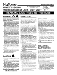
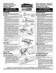
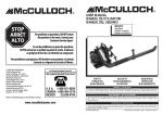
SERVICE PARTS
PIEZAS DE SERVICIO
MODEL MHS120L
MODELO MHS120L
24
SERVICE PARTS
KEY PART NUMBER
NO.
NO. PIEZ
NO.
CÓDIGO
Housing
Venturi Plate (Includes Key No. 9)
Blower
Motor
Motor Cup
Motor Mounting Rubber (2 Req.)
1
2
3
4
5
6
97009275
97014513
97011270
97012137
95000963
99100412
1
2
3
4
5
6
Blower Wheel
Screw, #8-18 x .375 Black
(9 Req.)*
Screw, #8-18 x .625 Zinc
Wire Cover/Harness Assembly
(Includes Key No. 24)
Ground Clip
Wire Clip (2 Req.)
Sheet Metal Nut, #8-18 (4 Req.)
7
8
99110735
99150491
7
8
9
10
99150571
97011912
9
10
11
12
13
99390015
99420643
93260454
11
12
13
14
15
16
17
18
19
20
21
97014185
98003036
99420631
99110736
99150542
97012135
99230342
97011909
14
15
16
17
18
19
20
21
22
23
24
**
97011835
97011164
99150570
99078495
22
23
24
**
Damper/Duct Connector
Mounting Bracket (4 Req.)
Grille Nut (2 Req.)
Light Lens
Screw, #6-20 x 2.875 (2 Req.)
Lamp Socket Assembly
Rivet, .125 Dia. x .212 *
Grille Assembly (Includes Key
Nos. 19 & 20)
Humidity Control Assembly
Motion Control Assembly
Screw, #8-18 x .375 Zinc
Lens Mask
* Standard Hardware. May be purchased locally.
** Not shown.
Order service parts by "PART NO." - NOT by "KEY NO."
PIEZAS DE SERVICIO
Caja
Placa Venturi (incluye código 9)
Soplador
Motor
Cubierta del motor
Goma de montaje del motor (se
necesitan 2)
Disco del soplador
Tornillo negro #8-18 x 0,375
(se necesitan 9)*
Tornillo de zinc #8-18 x 0,625
Cubierta de cable/Conjunto de cables
preconfigurados (incluye código 24)
Clip de tierra
Clip de cable (se necesitan 2)
Tuerca de hoja de metal #8-18
(se necesitan 4)
Conector amortiguador/conducto
Soporte de montaje (se necesitan 4)
Tuerca de la rejilla (se necesitan 2)
Lente de la luz
Tornillo, #6-20 x 2,875 (se necesitan 2)
Conjunto del cubo de la bombilla
Remache, 0,125 de diámetro x 0,212*
Conjunto de la rejilla
(incluye códigos 19 y 20)
Conjunto de control de humedad
Conjunto de control de movimiento
Tornillo, #8-18 x 0,375 zinc
Máscara del lente
* Material estándar. Puede ser adquirido localmente
** No se muestra
Encargue piezas de servicio por "NO. PIEZ" - NO por "NO. CODIGO".
7
BROAN -NUTONE ONE YEAR LIMITED
WARRANTY
Broan-NuTone warrants to the original consumer purchaser of its products that such
products will be free from defects in materials
or workmanship for a period of one year from
the date of original purchase. THERE ARE
NO OTHER WARRANTIES, EXPRESS OR
IMPLIED, INCLUDING, BUT NOT LIMITED
TO, IMPLIED WARRANTIES OF MERCHANTABILITY OR FITNESS FOR A PARTICULAR PURPOSE.
During this one-year period, Broan-NuTone
will, at its option, repair or replace, without
charge, any product or part which is found to
be defective under normal use and service.
THIS WARRANTY DOES NOT EXTEND TO
FLUORESCENT LAMP STARTERS AND
TUBES. This warranty does not cover (a) normal maintenance and service or (b) any products or parts which have been subject to misuse, negligence, accident, improper maintenance or repair (other than by Broan-NuTone),
faulty installation or installation contrary to recommended installation instructions.
The duration of an implied warranty is limited
to the one-year period as specified for the express warranty. Some states do not allow limitation on how long an implied warranty lasts,
so the above limitation may not apply to you.
BROAN-NUTONE’S OBLIGATION TO REPAIR OR REPLACE, AT BROAN-NUTONE'S
OPTION, SHALL BE THE PURCHASER’S
SOLE AND EXCLUSIVE REMEDY UNDER
THIS WARRANTY. BROAN-NUTONE SHALL
NOT BE LIABLE FOR INCIDENTAL, CONSEQUENTIAL OR SPECIAL DAMAGES
ARISING OUT OF OR IN CONNECTION
WITH PRODUCT USE OR PERFORMANCE.
Some states do not allow the exclusion or
limitation of incidental or consequential damages, so the above limitation may not apply to
you.
This warranty gives you specific legal rights,
and you may also have other rights, which vary
from state to state. This warranty supersedes
all prior warranties.
To qualify for warranty service, you must (a)
notify Broan-Nutone at the address stated below or telephone: 1-800-637-1453, (b) give
the model number and part identification and
(c) describe the nature of any defect in the
product or part. At the time of requesting warranty service, you must present evidence of
the original purchase date.
Broan-NuTone LLC
926 West State Street
Hartford, WI 53027
1-800-637-1453
Broan-NuTone LLC, 926 West State Street, Hartford, WI 53027 (1-800-637-1453)
GARANTIA BROAN-NUTONE
LIMITADA POR UN AÑO
Broan-NuTone garantiza al comprador
consumidor original de sus productos que tales
productos estarán libres de defectos en
materiales o en mano de obra por un período
de un año a partir de la fecha original de compra.
NO EXISTEN OTRAS GARANTIAS,
EXPLICITAS O IMPLICITAS, INCLUYENDO,
PERO NO LIMITADAS A, GARANTIAS
IMPLICITAS DE COMERCIALIZACION O
APTITUD PARA UN PROPOSITO PARTICULAR.
Durante el período de un año, y a su propio
criterio, Broan-NuTone
reparará o
reemplazará, sin costo alguno cualquier
producto o pieza que se encuentre defectuosa
bajo condiciones normales de servicio y uso.
ESTA GARANTIA NO SE APLICA A TUBOS Y
ARRANCADORES
DE
LAMPARAS
FLUORESCENTES. Esta garantía no cubre (a)
mantenimiento y servicio normales o (b)
cualquier producto o piezas que hayan sido
utilizadas de forma errónea, negligente, que
hayan tenido un accidente, o que hayan sido
reparadas o mantenidas inapropiadamente (por
otras compañías que no sean Broan-NuTone),
instalación defectuosa, o instalación contraria
a las instrucciones de instalación
recomendadas.
La duración de cualquier garantía implícita se
limita a un período de un año como se especifica
en la garantía expresa. Algunos estados no
permiten limitaciones en cuanto al tiempo de
expiración de una garantía implícita, por lo que
la limitación antes mencionada puede no
aplicarse a usted.
LA OBLIGACION DE BROAN-NUTONE DE
REPARAR O REEMPLAZAR, SIGUIENDO EL
CRITERIO DE BROAN-NUTONE, DEBERA
SER EL UNICO Y EXCLUSIVO RECURSO LEGAL DEL COMPRADOR BAJO ESTA
GARANTIA. BROAN-NUTONE NO SERA
RESPONSABLE
POR
DAÑOS
INCIDENTALES, CONSIGUIENTES, O POR
DAÑOS ESPECIALES QUE SURJAN A RAIZ
DEL USO O DESEMPEÑO DEL PRODUCTO.
Algunos estados no permiten la exclusión o
limitación de daños incidentales o consiguientes,
por lo que la limitación antes mencionada puede
no aplicarse a usted. Esta garantía le proporciona
derechos legales específicos, y usted puede
también tener otros derechos, los cuales varían
de estado a estado. Esta garantía reemplaza
todas las garantías anteriores.
Para calificar en la garantía de servicio, usted
debe (a) notificar a Broan-NuTone al domicilio
que
se
menciona
abajo
o
al
teléfono:1-800-637-1453, (b) dar el número del
modelo y la identificación de la pieza, y (c)
describir la naturaleza de cualquier defecto en
el producto o pieza. En el momento de solicitar
servicio cubierto por la garantía, usted debe de
presentar evidencia de la fecha original de
compra.
Broan-NuTone LLC
926 West State Street
Hartford, WI 53027
EE. UU.
1-800-637-1453
99042976F