1
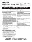
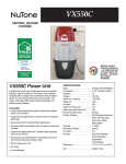
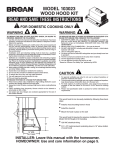
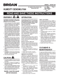
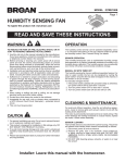
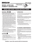
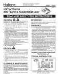
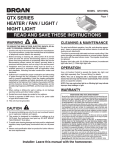
MODEL QTX110SL
Page 1
HUMIDITY SENSING
FAN / LIGHT / NIGHT LIGHT
READ AND SAVE THESE INSTRUCTIONS
To register this product visit:
www.broan.com
WARNING
OPERATION
TO REDUCE THE RISK OF FIRE, ELECTRIC
SHOCK, OR INJURY TO PERSONS, OBSERVE THE FOLLOWING:
1. Usethisunitonlyinthemannerintended
bythemanufacturer.Ifyouhavequestions,
contactthemanufacturerattheaddressor
telephonenumberlistedinthewarranty.
2. Before servicing or cleaning unit, switch
poweroffatservicepanelandlocktheservicedisconnectingmeanstopreventpower
frombeingswitchedonaccidentally.When
theservicedisconnectingmeanscannotbe
locked,securelyfastenaprominentwarning
device,suchasatag,totheservicepanel.
3. Installationworkandelectricalwiringmustbe
donebyaqualifiedperson(s)inaccordance
with all applicable codes and standards,
includingfire-ratedconstructioncodesand
standards.
4. Sufficientairisneededforpropercombustion and exhausting of gases through the
flue(chimney)offuelburningequipmentto
preventbackdrafting.Followtheheatingequipment manufacturer’s guideline and safety
standardssuchasthosepublishedbythe
NationalFireProtectionAssociation(NFPA),
andtheAmericanSocietyforHeating,Refrigeration andAir Conditioning Engineers
(ASHRAE),andthelocalcodeauthorities.
5. Whencuttingordrillingintowallorceiling,do
notdamageelectricalwiringandotherhidden
utilities.
6. Ductedfansmustalwaysbeventedtothe
outdoors.
7. Acceptableforuseoveratuborshowerwhen
connectedtoaGFCI(GroundFaultCircuit
Interrupter)-protectedbranchcircuit.
8. Thisunitmustbegrounded.
The humidity control and fan can be
oper-ated separately. Use a 1- or 2-function wall control. Do not use a dimmer
switch to operate the humidity control or
light. See “Connect Wiring” for details.
CAUTION
1. Forgeneralventilatinguseonly.Donotuse
toexhausthazardousorexplosivematerials
andvapors.
2. Thisproductisdesignedforinstallationinflat
ceilingsonly.DONOTMOUNTTHISPRODUCTINAWALL.
3. Toavoidmotorbearingdamageandnoisy
and/orunbalancedimpellers,keepdrywall
spray,constructiondust,etc.offpowerunit.
4. Pleasereadspecificationlabelonproductfor
furtherinformationandrequirements.
Installer: Leave this manual
with the homeowner.
SENSOR OPERATION
This humidity-sensing fan responds to:
(a) rapid to moderate humidity increases
and(b)humidityabovea50%-100%relativehumidityset-point.(a)and(b)areset
with“SENSITIVITY” adjustment. Fan may
occasionallyturnon whenenviron-mental
conditionschange.Ifthefancontin-uously
respondstochangingenviron-mentalconditions,“SENSITIVITY”adjust-mentmaybe
required(seesectionbelow).
STATUS INDICATOR
Thisindicatorcanonlybeseenbylooking
directlyatit.Normalmodeis5-secondson
andoff.Ifitblinksrapidlyfor5-secondsand
thenoff,checksensorconnectionsongrille
andfanhousing.
MANUAL ON WITH TIMED OFF
For odor or vapor control, the fan can be
energizedbycyclingitswall-mountedswitch
ifoneisinstalled.Oncethefanhasbeen
turnedoninthismanner,itwillremainon
fortheset“TIMER”period.
Tomanuallyenergizethefan:
1. Go to Step 2 if switch is already on;
otherwise,turnswitchonformorethan
1second.
2. Switchoffforlessthan1second.
3. Switchbackonandfanwillturnon.
SENSITIVITY ADJUSTMENT
“SENSITIVITY” has been factory set for
mostshowerapplications.Ifthefanisina
tubareaorisusedfordampnesscontrol,the
“SENSITIVITY”mayneedtobeincreased
towardmaximum(“MAX.”).Ifthecontrolis
respondingtoooftentochangingenvironmentalconditions,adjustmenttowardless
(“MIN.”) “SENSITIVITY” may be required.
Toadjustthe“SENSITIVITY”:
1. Turn power off at electrical service
panel.
2. T h ro u g h t h e g r i l l e , l o c a te t h e
“SENSITIVITY”screwdriverslot.
3. Using a small, flat-blade screwdriver,
carefully rotate“SENSITIVITY” adjustmenttoward“MAX.”or“MIN.”
4. Turnpoweronandcheckoperationby
turning on shower or other humidity
sourceuntilfanturnson.
5. Repeatabovestepsifnecessary.
TIMER ADJUSTMENT
Thishumidity-sensingfanhasa“TIMER”.It
isuser-adjustablefrom5to60minutesand
is factory-set at 20 minutes.The“TIMER”
controls how long the fan remains on (a)
afterriseinhumidityand(b)humiditylevel
arebothbelowtheuser-adjustable“SENSITIVITY”settingorafterbeingenergizedby
cyclingpowerswitch.
Toadjustthe“TIMER”:
1. Disconnectpoweratelectricalservice
panel.
2. Throughthegrille,locatethe“TIMER”
screwdriverslot.
3. Using a small, flat-blade screwdriver,
carefullyrotate“TIMER”adjustmentto
desiredsetting(5to60minutes).
4. Checkoperationbycyclingpowerswitch
asinstructedunder“MANUALONWITH
TIMEDOFF”orbyturningonahumidity
sourceuntilfanturnson.
5. Check “TIMER” setting with watch or
clockafterturninghumiditysourceoffif
itwasturnedonitStep4.
6.Repeatabovestepsifnecessary.
CLEANING &
MAINTENANCE
Forquietandefficientoperation,longlife,
andattractiveappearance-lowerorremove
grille and vacuum interior of unit with the
dustingbrushattachment.
The motor is permanently lubricated and
never needs oiling. If the motor bearings
are making excessive or unusual noises,
replace the motor with the exact service
motor.Theimpellershouldalsobereplaced.
SENSOR CLEANING
Thehumiditysensorismountedinthegrille.
Thesensorwilloperatemostreliablywhen
cleanedoccasionallyasfollows:
1. Disconnectpoweratserviceentrance.
2. Removethegrille.Useadrydustcloth,
clean toothbrush, or lightly vacuum to
cleansensorandgrille.DONOTUSE
ABRASIVE CLOTH, STEEL WOOL
PADS,ORSCOURINGPOWDERS.
3. DONOTUSEcleaningsprays,solvents,
orwateronornearthesensor!
MODEL QTX110SL
Page 2
TYPICAL INSTALLATIONS
Housing mounted to
I-joists.
Housing mounted
anywhere between
I-joists using hanger bars.
Housing mounted
anywhere between
joists using hanger bars.
Housing mounted to joists.
• Locateunitabove(GFCIprotectedcircuitrequired)or
within5feetofshowerhead.
• Locateunitawayfromheatingorcoolingsources
whichcanaffecthumiditylevels.
• Donotlocatenearwindow.Unitmayrespondtothe
outdoorhumiditylevel.
• Unitmustbeinstalledinceilingtoproperlysense
moisture.
• Locateunitonlyonflatceilingsupto12feethighfor
propersensing.
• Thefanwilloperatemostefficientlywhenlocated
wheretheshortestpossibleductrunandminimum
numberofelbowswillbeneeded.
2. Plan the wiring.
•
•
•
Plantosupplytheunitwithproperlinevoltageand appropriatepowercable.Powercableshouldbe
routedtotheswitchboxfirstandthentotheunit
(See“CONNECTWIRING”onpage3).
Donotoperatethisunitwithaspeedcontrol. Damagetothesensorunitwillresult.
Lightornight-lightmaybeinstalledwithawall- mountedmotioncontrol.
INSTALL HOUSING &
DUCT
1a. Mount
housing
to joist or
I-joist.
Housing mounted anywhere
between trusses using
hanger bars.
Housing mounted anywhere
between trusses using hanger
bars.
PLAN THE INSTALLATION
1. Choose the
installation
location.
Thelocationof
yourhumidity
sensingfanis
veryimportant.
Usethefollowingguidelines
forbestoperation:
ROOFCAP*
6-IN.ROUND
DUCT*
*Purchase
separately
6-IN.ROUND
ELBOW*
WALL
CAP*
Useapliersto
bendhousing
TABS
TABSout
to900.Hold
housingin
placesothat
thehousing
SPACER
tabscontact
(useformountingtoI-Joist)
thebottom
ofthejoist.
Thehousing
mountswith
four(4)screws
ornails.Screw
ornailhousing
tojoistthrough
lowestholesin
eachmounting
I-JOIST
flange,then
throughhighestholes.NOTE:MountingtoI-JOIST
(shown)requiresuseofSPACERS(included)
betweenthehighestholeofeachmountingflange
andtheI-joist.
OR
MODEL QTX110SL
Page 3
1b. Mount housing anywhere between
trusses, joists, or I-joists using hanger
bars.
Slidinghangerbarsareprovidedtoallowforaccuratepositioningofhousinganywherebetweenframing.Theycanbe
usedonalltypesofframing(I-joist,standardjoist,andtruss
construction)andspanupto24”.
2. Attach damper/
duct connector.
Snapdamper/ductconnectorontohousing.Make
sureconnectorisflush
withtopofhousingand
damperflapfallsclosed.
TAB
SCREWS(4)
3. Install
6-inch round ductwork.
MOUNTING
CHANNEL(2)
HANGER
BAR(4)
Connect6-inchround
ductworktodamper/duct
connector.Runductwork
toaroofcaporwallcap.
Tapeallductworkconnectionstomakethem
secureandairtight.
CONNECT WIRING
Attach the MOUNTING CHANNELS to the housing using
theSCREWSsupplied.MakesureTABSface“up”asshown.
Usethesetofchannelmountingholes(marked“STD”)to
mountthehousingflushwiththebottomofthedrywall.Use
the other set of holes (not marked) to mount the housing
flushwiththetopofthedrywall.
WIRING OPTION #1 - Allows fan to operate in automatic mode or manual
mode (for odor control) by cycling ON/OFF switch.
MODEL 66V/66W, P66V/P66W
3-FUNCTION CONTROL (PURCHASE SEPARATELY)
LIGHT
(ON/OFF)
BLK
BLU
RED
RED
LIGHT
COM
NIGHT LIGHT
(ON/OFF)
HOLEFOROPTIONAL
SCREWMOUNTING(4)
*SCREW(2)
NIGHT LIGHT
WHT
BLK
FAN
(AUTO/OFF)
ORG
HUMIDITY
CONTROL
BRN
BLK
120
VAC
LINE
IN
BLK
GRD
WHT
WHT
WHT
WHT
FAN
WHT
GRD
SWITCH BOX
UNIT
WIRING OPTION #2 - Fan can be turned ON, OFF, or set to operate automatically.
MODEL 77DV, 77DW, P77DV, P77DW
4-FUNCTION CONTROL (PURCHASE SEPARATELY)
BLK
NAIL(4)
BOTTOMEDGE
OFFRAMING
ExtendHANGERBARStothewidthoftheframing.
Hold ventilator in place with the hanger bar tabs wrapping
aroundtheBOTTOMEDGEOFTHEFRAMING.
NAILventilatortoframingorfastenwithscrews(notprovided)
throughHOLESnearnails.
*
Toensureanoise-freemount:Securehangerbarstogether
with SCREWS or use a pliers to crimp mounting channels
tightlyaroundhangerbars.
FAN
(ON/OFF/AUTO)
BLK
RED
RED
ORG
BLU
BLK
BRN
COM
NIGHT LIGHT
(ON/OFF)
LIGHT
(ON/OFF)
BLK
120
VAC WHT
LINE
IN
GRD
HUMIDITY
CONTROL
FAN
WHT
WHT
WHT
WHT
RED
RED
BLK
BLU
NIGHT LIGHT
COM
BLK
WHT
LIGHT
WHT
GRD
SWITCH BOX
4. Connect electrical wiring.
UNIT
Run120VAChousewiringtoinstallationlocation.Use
properULapprovedconnectortosecurehousewiringto
wiringplate.Connectwiresasshowninwiringdiagrams.
MODEL QTX110SL
INSTALL GRILLE
SERVICE PARTS
Page 4
6. Finish ceiling.
Installceilingmaterial.Cutoutaroundhousing.
7. Plug in wiring.
Plugwiringintotheproperreceptacles.
8. Attach grille to
housing.
9. Push grille against
ceiling.
Squeezegrillespringsand
insertthemintoslotson
eachsideofhousing.
Replacement parts can be
ordered on our website.
Please visit us at
www.broan.com
10. Remove light lens. 11. Install light bulbs.
Carefullyinsertasmallflatbladescrewdriverbetween
grilleandlens.Prylens
out.
WARRANTY
Purchaseanincandescent
bulb(100Wmax.)anda
4Wincandescentnightlightbulbandscrewthem
intotheirsockets.Replace
lens.
BROAN-NUTONE THREE YEAR LIMITED WARRANTY
Broan-NuTone warrants to the original consumer purchaser of its products that such products will be free
from defects in materials or workmanship for a period of three years from the date of original purchase.
THERE ARE NO OTHER WARRANTIES, EXPRESS OR IMPLIED, INCLUDING, BUT NOT LIMITED TO,
IMPLIED WARRANTIES OF MERCHANTABILITY OR FITNESS FOR A PARTICULAR PURPOSE.
During this three-year period, Broan-NuTone will, at its option, repair or replace, without charge, any
product or part which is found to be defective under normal use and service.
THIS WARRANTY DOES NOT EXTEND TO FLUORESCENT LAMP STARTERS, TUBES, HALOGEN AND
INCANDESCENT BULBS, FUSES, FILTERS, DUCTS, ROOF CAPS, WALL CAPS AND OTHER ACCESSORIES
FOR DUCTING. This warranty does not cover (a) normal maintenance and service or (b) any products or
parts which have been subject to misuse, negligence, accident, improper maintenance or repair (other than
by Broan-NuTone), faulty installation or installation contrary to recommended installation instructions.
The duration of any implied warranty is limited to the three-year period as specified for the express
warranty. Some states do not allow limitation on how long an implied warranty lasts, so the above
limitation may not apply to you.
BROAN-NUTONE’S OBLIGATION TO REPAIR OR REPLACE, AT BROAN-NUTONE’S OPTION, SHALL
BE THE PURCHASER’S SOLE AND EXCLUSIVE REMEDY UNDER THIS WARRANTY. BROAN-NUTONE
SHALL NOT BE LIABLE FOR INCIDENTAL, CONSEQUENTIAL OR SPECIAL DAMAGES ARISING OUT OF
OR IN CONNECTION WITH PRODUCT USE OR PERFORMANCE. Some states do not allow the exclusion
or limitation of incidental or consequential damages, so the above limitation or exclusion may not apply
to you.
This warranty gives you specific legal rights, and you may also have other rights, which vary from state to
state. This warranty supersedes all prior warranties.
To qualify for warranty service, you must (a) notify Broan-NuTone at the address or telephone number
below, (b) give the model number and part identification and (c) describe the nature of any defect in the
product or part. At the time of requesting warranty service, you must present evidence of the original
purchase date.
Broan-NuTone LLC, 926 W. State Street, Hartford, Wisconsin 53027 www.broan.com 800-558-1711
Key No.
Part No.
1
2
3
4
5
6
7
8
9
10
11
12
13
97016466
97016450
98010102
99170245
97017086
97017452
97016965
99140199
99111345
99271344
99111293
SQTHB1
99420665
SERVICE NOTE
To remove Blower Assembly: Unplug motor.
Remove thumbscrew (13) from motor plate
(6) flange. Find the single TAB on the motor
plate (located next to the receptacle). Push
up near motor plate tab while pushing out
on side of housing. Or insert a straight-blade
screwdriver into slot in housing (next to tab)
and twist screwdriver.
Description
Housing
DuctConnector-6”
WiringPlate
Screw,#8-18X.375
WirePanel/HarnessAssembly*
BlowerAssembly*
(includeskeynos.6&7)
GrilleAssembly*
(includeskeynos.9,10&14)
GrilleSpring(2req’d)
Lens
SensorWireHarness
Spacer(2supplied)
HangerBarKit
Thumbscrew,#8-18x.375
*PartsnotlistedareincludedwithAssembly.
Orderservicepartsby“PartNo.”-notby“KeyNo.”
99043586E