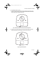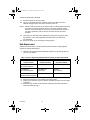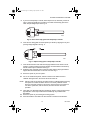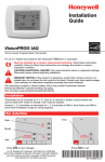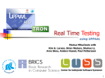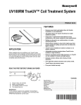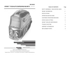
1
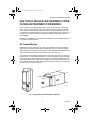
69-1573-2.fm Page 1 Tuesday, April 26, 2005 3:57 PM
UV100E Ultraviolet System
OWNER’S GUIDE
69-1573-2
69-1573-2.fm Page 2 Tuesday, April 26, 2005 3:57 PM
UV100E ULTRAVIOLET SYSTEM
American Lung Association® Health House® Program and
Honeywell Working Together For Better Air
Did you know that the average person breathes 3400 gallons(12,870 liters) of air each
day * and spends 90% of that day inside?**
Indoor air quality products from Honeywell are designed to help make your home more
comfortable—from zoning products that allow you to control the temperature in
individual areas of the home to humidifiers and comfort control centers that help
balance the moisture content of your indoor air.
Honeywell is proud to be a partner of the American Lung Association® Health House®
program that provides guidelines for constructing homes with improved air quality and
ventilation.
For more information on ways to improve the air inside your home, please visit the
Health House website at:
www.healthhouse.org
and the American Lung Association website at: ww.lungusa.org
The American Lung Association and its Health House program do not endorse
products.
For more information about Honeywell Indoor Air Quality products, visit:
www.honeywell.com/yourhome
or call:
1-800-345-6770 x531
*EPA.National Air Quality 1999 Status & Trends.
**Indoor Air Pollution, An Introduction for Health Professionals, EPA, US Government Printing Office #1994523-217/81322.
IMPORTANT
Please read these instructions and keep them in your records.
69-1573-2
2
69-1573-2.fm Page 3 Tuesday, April 26, 2005 3:57 PM
UV100E ULTRAVIOLET SYSTEM
HOW YOUR ULTRAVIOLET AIR TREATMENT SYSTEM
OR SURFACE TREATMENT SYSTEM WORKS
Your UV System uses patented SmartLamp™ control technology that monitors the
HVAC system to operate the lamp only when needed. This technology extends bulb
life up to five times and reduces power consumption, lowering operating costs. Your
UV System also includes protection from extreme conditions that may be found in your
heating and cooling system and local diagnostics with the SmartLamp™ LED and
reset capability.
Depending on installation, your UV System can operate as an Air Treatment System or
as a Surface Treatment System.
Air Treatment System
Installed in the return air duct of your system, your Ultraviolet Air Treatment System
kills a high percentage of airborne germs circulating through your forced air heating
and cooling system. Individual results depend on careful installation and maintenance
and on the actual amount of time your system fan operates. See Fig. 1.
Your Ultraviolet Air Treatment System uses the on-board air flow sensor or input from
the Enviracom™ communication terminals to monitor air flowing through your heating
and cooling system. The UV system turns on when air is flowing and leaves the lamp
on for 40 minutes after the airflow stops. If airflow resumes during the 40 minutes, the
timer resets to 40 minutes. When no airflow is detected for 40 minutes, the lamp turns
off until the next occurrence of airflow.
ENT
ISSEM
VERT
les
ING/A
nue et
! WARN
rendre
la peau
e.
pour et bien comp
enanc
Nocifs
la maint
ez lire
Veuill llation et
l’insta
!
WAR
NING
Noc
/AVE
RTIS
Veuiifs pour
l’instllez lire la peau SEMENT
allat
ion et bien nue et
et la com
les
main pren
tena dre
nce.
M22858
Fig. 1. Typical Air Treatment System installations.
3
69-1573-2
69-1573-2.fm Page 4 Tuesday, April 26, 2005 3:57 PM
UV100E ULTRAVIOLET SYSTEM
Surface Treatment System
When installed next to the cooling coil of your system, your Ultraviolet Surface
Treatment System prevents a high percentage of the growth of micro-organisms such
as mold that may grow on duct surfaces, coils, and drain pans. Individual results
depend on careful installation and maintenance. See Fig. 2.
Your Ultraviolet Surface Treatment System operates a steady three-hours-on/
three-hours-off cycle. With Enviracom™ communication terminals hooked up,
your UV System turns off for the Winter 30 days after the last call for cooling occurs.
And your UV System turns on and resumes the on/off cycle with the first call for cooling
in the Spring.
ENT
ISSEM
VERT
les
ING/A
nue etendre
! WARN
la peau
.
pour bien compr
nance
Nocifs z lire et la mainte
Veuillellation et
l’insta
ENT
SEM
RTIS
/AVE
et les
NING
nue rendre
! WAR
la peaucomp ce.
s pour et bien tenan
Nociflez lire et la main
Veuil llation
l’insta
M22860
Fig. 2. Typical Surface Treatment System installations.
You can capture and minimize micro-organisms passing through your forced air
system when you combine your UV System with a high-efficiency air filtration system
like an electronic air cleaner. Talk to your installer about adding an electronic air
cleaner to complement your UV System and provide added protection for you and your
family.
69-1573-2
4
69-1573-2.fm Page 5 Tuesday, April 26, 2005 3:57 PM
UV100E ULTRAVIOLET SYSTEM
Enviracom™ Communications Capabilities:
• Communicates with homeowner through three-wire communication bus using
24 Vac thermostat connections.
— Hooked up to Air Treatment System (single-bulb and dual-bulb) models: uses
thermostat load information instead of airflow sensor.
— Hooked up to Surface Treatment System model: uses thermostat load
information to operate during times evaporator coil may be exposed to
moisture to extend lamp life beyond two years.
• Sends messages to communicate reset and receives remote reset, when available.
— Bulb change indication cannot be reset by cycling power.
— When Enviracom is transmitting messages, shows flashing green Enviracom
LED on bottom of unit.
• Other messages include percent of bulb life remaining, internal faults, and lamp
energized.
— Control calculates percent of lamp run time/starts remaining and sends out this
information through an Enviracom message.
When Enviracom is transceiving messages, shows solid green Enviracom LED on
bottom of unit.
5
69-1573-2
69-1573-2.fm Page 6 Tuesday, April 26, 2005 3:57 PM
UV100E ULTRAVIOLET SYSTEM
BE SURE TO READ WARNINGS AND CAUTIONS
BEFORE USING YOUR UV SYSTEM
WARNING
UV Light Hazard.
Harmful to bare skin and eyes.
Can cause temporary or permanent loss of vision.
Never look at bulbs while illuminated.
View illumination only through light indicator located on lamp handle.
To prevent exposure to ultraviolet light, disconnect power to Ultraviolet System
before servicing any part of heating and air conditioning system.
Do not mount device in location that allows ultraviolet light to be seen after
installation.
Do not attempt to bypass duct mount switch.
Do not attempt to open housing; unit is sealed to prevent ultraviolet light
exposure.
CAUTION
Personal Injury Hazard.
Power supply can cause electrical shock.
Disconnect power supply before cleaning or replacing ultraviolet bulb(s).
Do not open base unit or lamp handle; there are no user-serviceable
components inside.
CAUTION
Breakable Glass Hazard.
Can cause personal injury.
Be careful when inserting bulb(s) into lamp base.
Wear protective gloves when handling bulb(s).
CAUTION
UV Lamp Burn Hazard.
Harmful to bare skin.
Can cause severe burns.
Disconnect power 15 minutes before removing ultraviolet bulb(s).
69-1573-2
6
69-1573-2.fm Page 7 Tuesday, April 26, 2005 3:57 PM
UV100E ULTRAVIOLET SYSTEM
MERCURY NOTICE
This device contains mercury in the sealed ultraviolet bulb(s). Do not place
your used bulb(s) in the trash. Dispose of properly.
Broken Bulb Cleanup.
Do not use a household vacuum.
Sweep debris (phosphor/glass) into a plastic bag and dispose of properly.
Contact your local waste management authority for instructions regarding
recycling and the proper disposal of old bulb(s).
7
69-1573-2
69-1573-2.fm Page 8 Tuesday, April 26, 2005 3:57 PM
UV100E ULTRAVIOLET SYSTEM
HOW YOU CAN CHECK YOUR ULTRAVIOLET SYSTEM
Your UV System is designed to prevent accidental contact with electrical voltage and
with ultraviolet rays in the sealed unit⎯the ultraviolet lamp does not illuminate unless
the base is mounted on your forced air system duct.
It is recommended that every month you verify that your ultraviolet lamp is operating.
View the bulb only through the lamp light indicator on the lamp handle. See Fig. 3.
Do not attempt to look into the duct at the illuminated bulb(s).
If the light is not on when you check your UV System, briefly push the reset button for
one second. This brings the lamp on for 40 minutes (Air Treatment System) or for 30
minutes (Surface Treatment System). Pressing the reset button for five seconds resets
all internal timers. Cycling power does not reset the internal timers.
LAMP LIGHT INDICATOR
LED CHANGE INDICATOR
RESET BUTTON
M22856
Fig. 3. Lamp light indicator, LED change indicator and reset button.
The LED indicator on the front of your UV System operates as follows:
LED Status
Indicates
Homeowner Action
Off
100 to 11% bulb lifea remaining Nothing
Flashing
10 to 1% bulb lifea remaining
Purchases bulb(s)
Solid
0% bulb lifea remaining
Replaces bulb(s)
aBulb life means emitting adequate amount of
UV-C energy to maintain an effective kill
rate. At 0% bulb life remaining, the bulbs continue to operate until catastrophic bulb
failure (bulb burns out) but the kill rate becomes rapidly negligible.
69-1573-2
8
69-1573-2.fm Page 9 Tuesday, April 26, 2005 3:57 PM
UV100E ULTRAVIOLET SYSTEM
HOW YOU CAN MAINTAIN YOUR UV SYSTEM
You should regularly clean your UV System to maintain peak effectiveness of your air
treatment or surface treatment system. Replace the ultraviolet bulb when LED status
light on the front of your UV System is on steadily.
Quarterly Bulb Cleaning
Bulb cleaning is recommended as routine maintenance four times a year or every
three months. Use the UV Bulb Cleaning Reminder Schedule, Fig. 4, to help establish
and track your regular cleaning schedule.
UV BULB CLEANING REMINDER SCHEDULE
, (year)
INSTALLATION DATE: (month)
YEAR
J
F
M
A
M
J
J
A
S
O
N
D
M13516A
Fig. 4. UV bulb cleaning reminder schedule.
To clean your bulbs:
1. Disconnect the power to your heating and cooling system.
2. Unplug or turn off power to your UV System and allow the bulb to cool for at
least 15 minutes.
9
69-1573-2
69-1573-2.fm Page 10 Tuesday, April 26, 2005 3:57 PM
UV100E ULTRAVIOLET SYSTEM
3.
Rotate your lamp handle counterclockwise and gently pull the lamp handle to
remove the bulb. See Fig. 5.
M22842
Fig. 5. Remove lamp bulb.
4.
Holding the lamp handle, wipe the lamp glass using a soft cloth dampened with
glass cleaner. If you touch the lamp glass with your hands, be sure to clean the
area of any oils left from bare hands. See Fig. 6.
M22844
Fig. 6. Clean glass with soft cloth.
5.
Also wipe away any dust that may have collected between the lamp light
indicator base and the black bulb base. See Fig. 7.
LAMP LIGHT INDICATOR BASE
M22846
Fig. 7. Wipe lamp light indicator base.
69-1573-2
10
69-1573-2.fm Page 11 Tuesday, April 26, 2005 3:57 PM
UV100E ULTRAVIOLET SYSTEM
6.
7.
Dry bulb with a clean, dry cloth.
Insert the bulb into the base with the lamp light indicator at the eleven o’clock
position. Continue pushing and gently rotating counterclockwise until the lamp
handle inserts fully into the base. See Fig. 8.
M22848
Fig. 8. Position bulb for insertion back into the lamp base.
8.
Rotate the lamp handle clockwise until it snaps into place with the lamp light
indicator aligned with the raised button on the unit cover. See Fig. 9.
M22850
Fig. 9. Snap bulb into place.
11
69-1573-2
69-1573-2.fm Page 12 Tuesday, April 26, 2005 3:57 PM
UV100E ULTRAVIOLET SYSTEM
9.
10.
Reconnect power to your UV System.
For UV Air Treatment Systems, wait ten minutes for the airflow sensor to
calibrate. During this time, the furnace fan must remain off.
NOTE: Failure to wait ten minutes for the airflow sensor to calibrate before powering
the system fan causes the airflow sensor to incorrectly calibrate and the
device to incorrectly function. If this occurs, remove power to the furnace or
turn off the system fan, wait ten minutes, and then resume normal fan
operation.
11.
12.
Verify that your ultraviolet bulb is operating by viewing only through the lamp
light indicator on the lamp handle. Never look directly at your bulb while
it is illuminated.
Reconnect power to your heating and cooling system.
Bulb Replacement
Replacement of the bulb in your ultraviolet lamp when the LED is solidly lighted is
required to maintain effectiveness.
1.
Obtain the correct replacement bulb/handle assembly or replacement bulb for
your unit. See Table 1.
Table 1. Select a Replacement Bulb/Handle Assembly or Replacement Bulb.
Unit Description
Replacement Bulb/
Handle Assembly
SnapLamp™
Replacement Bulb
UV100E1043
Air Treatment System
UC100E1006
UC18W
UV100E2009
Air Treatment System
UC100E1014
(twin pack)
UC36W
(two needed)
UV100E3007
Surface Treatment System
UC100E1030
UC36W
2.
3.
4.
Disconnect the power to your heating and cooling system.
Unplug or turn off power to your UV System and allow the bulb to cool for at least
15 minutes.
Rotate the lamp handle counterclockwise and gently pull the lamp handle to
remove the bulb. See Fig. 5.
69-1573-2
12
69-1573-2.fm Page 13 Tuesday, April 26, 2005 3:57 PM
UV100E ULTRAVIOLET SYSTEM
5.
If you have a SnapLamp™ handle, follow steps 5 and 6; otherwise, proceed to
step 7. Grasp the SnapLamp™ handle in one hand and the lamp glass in the
other and pull straight apart. See Fig. 10.
M22852
Fig. 10. Disconnect lamp glass from SnapLamp™ handle.
6.
Insert the new lamp glass into the SnapLamp™ handle by aligning the key and
pushing straight together. See Fig. 11.
M22854
Fig. 11. Replace lamp glass in SnapLamp™ handle.
7.
8.
9.
10.
Insert the bulb into the base with the lamp light indicator at the eleven o’clock
position. Continue pushing and gently rotating counterclockwise until the lamp
handle inserts fully into the base. See Fig 8.
Rotate the lamp clockwise until it snaps into place with the lamp light indicator
aligned with the raised button on the unit cover. See Fig. 9.
Reconnect power to your UV System.
For UV Air Treatment Systems, wait ten minutes for the airflow sensor to
calibrate. During this time, the furnace fan must remain off.
NOTE: Failure to wait ten minutes for the airflow sensor to calibrate before powering
the system fan causes the airflow sensor to incorrectly calibrate and the
device to incorrectly function. If this occurs, remove power to the furnace or
turn off the system fan, wait ten minutes, and then resume normal fan
operation.
11.
12.
13.
Verify that your ultraviolet bulbs are operating by viewing only through the lamp
light indicator on the lamp handle. Never look directly at your bulbs while
illuminated.
Reconnect power to your heating and cooling system.
Press and hold the reset button for five seconds to reset the internal timers.
13
69-1573-2
69-1573-2.fm Page 14 Tuesday, April 26, 2005 3:57 PM
UV100E ULTRAVIOLET SYSTEM
Five-Year Limited Warranty
Honeywell warrants this product, excluding bulbs, to be free from defects in the workmanship or
materials, under normal use and service, for a period of five (5) years from the date of purchase
by the consumer. If, at any time during the warranty period, the product is defective or
malfunctions, Honeywell shall repair or replace it (at Honeywell’s option) within a reasonable
period of time.
If the product is defective,
(i) return it, with a bill of sale or other dated proof of purchase, to the retailer from which you
purchased it, or
(ii) package it carefully, along with proof of purchase (including date of purchase) and a short
description of the malfunction, and mail it, postage prepaid, to the following address:
Honeywell Return Goods
Dock 4 MN10-3860
1885 Douglas Dr N
Golden Valley, MN 55422
This warranty does not cover removal or reinstallation costs. This warranty shall not apply if it is
shown by Honeywell that the defect or malfunction was caused by damage which occurred while
the product was in the possession of a consumer.
Honeywell’s sole responsibility shall be to repair or replace the product within the terms stated
above. HONEYWELL SHALL NOT BE LIABLE FOR ANY LOSS OR DAMAGE OF ANY KIND,
INCLUDING ANY INCIDENTAL OR CONSEQUENTIAL DAMAGES RESULTING, DIRECTLY OR
INDIRECTLY, FROM ANY BREACH OF ANY WARRANTY, EXPRESS OR IMPLIED, OR ANY
OTHER FAILURE OF THIS PRODUCT. Some states do not allow the exclusion or limitation of
incidental or consequential damages, so this limitation may not apply to you.
THIS WARRANTY IS THE ONLY EXPRESS WARRANTY HONEYWELL MAKES ON THIS
PRODUCT. THE DURATION OF ANY IMPLIED WARRANTIES, INCLUDING THE WARRANTIES
OF MERCHANTABILITY AND FITNESS FOR A PARTICULAR PURPOSE, IS HEREBY LIMITED
TO THE FIVE YEAR DURATION OF THIS WARRANTY. Some states do not allow limitations on
how long an implied warranty lasts, so the above limitation may not apply to you.
This warranty gives you specific legal rights, and you may have other rights which vary from state
to state.
If you have any questions concerning this warranty, please write Honeywell Customer Relations,
Honeywell, 1985 Douglas Dr N MN10-1461, Golden Valley, MN 55422. In Canada, write Retail
Products ON15-02H, Honeywell Limited/Honeywell Limitée, 35 Dynamic Drive, Scarborough,
Ontario, M1V4Z9.
69-1573-2
14
69-1573-2.fm Page 15 Tuesday, April 26, 2005 3:57 PM
UV100E ULTRAVIOLET SYSTEM
15
69-1573-2
69-1573-2.fm Page 16 Tuesday, April 26, 2005 3:57 PM
UV100E ULTRAVIOLET SYSTEM
Automation and Control Solutions
Honeywell International Inc. Honeywell Limited-Honeywell Limitée
1985 Douglas Drive North
35 Dynamic Drive
Golden Valley, MN 55422
Scarborough, Ontario M1V 4Z9
yourhome.honeywell.com
® U.S. Registered Trademark
© 2005 Honeywell International Inc.
69-1573-2 G.H. Rev. 04-05