1
(right border)
(left border)
9/32”
9/32”
HITACHI
Home Electronics Division
2003
Auto Digital
Convergence
Pocket Manual
Sears version 1.0.1
5/64”
(bottom of page #)
(right border)
(left border)
9/32”
9/32”
CONTENTS
Introduction
1
Equipment Requirements
4
Screen Overlay Jigs
5
Chassis/Model Cross Reference
7
Remote Control Configurations
10
Service Solutions
59
Magic Focus Operation
61
Touch-Up Alignment
62
Complete Alignment
73
DCU Error Code Table
95
2H Model Procedures
96
5/64”
(bottom of page #)
(right border)
(left border)
9/32”
9/32”
INTRODUCTION
INTRODUCTION
Getting Started with Digital Convergence
This handbook is designed to provide a simplified, step-bystep approach towards understanding the principles, troubleshooting, and adjusting of the Hitachi Digital Convergence
System. The handbook covers, in detail, the convergence procedures for all Hitachi Projection Televisions using the Digital
Convergence System, including the newer 2H models. Some
of these new models require the technician to perform the convergence adjustments in two completely separate modes, due
to the TV having two separate horizontal scanning frequencies.
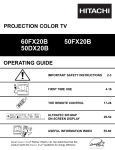
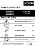
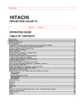
Digital Convergence Correction - History
Since 1991, Hitachi has manufactured Projection Television
products that use data stored in an EEPROM as convergence
correction data. The correction data is converted to analog
parabolic and sawtooth waveforms and sent to the respective
output devices. The first Hitachi model to use this system was
the 60SX1B/K.
D /A
C orrection
Am plifiers
EEPRO M
Adjustm ent
Point D ata
Service Technician
A/D
Interface
D igital
C onvergence
U nit
(D C U )
C ustom er
C onvergence
Yokes
The Digital Convergence adjustment process began by shorting two internal test points to set the unit to the Digital Convergence Adjustment Mode (DCAM). From the DCAM, or
service mode, the necessary adjustments were made to correct
the convergence errors.
1
5/64”
(bottom of page #)
(right border)
(left border)
9/32”
9/32”
The remote control was used to adjust the position of an internally generated crosshatch pattern for each CRT. While in
the DCAM/service mode, a number of buttons on the remote
control are allocated specifically for convergence adjustments, and no longer operate the functions indicated on their
button.
INTRODUCTION
INTRODUCTION
Adjustments of the crosshatch pattern must be matched to a
precision reference overlay attached to the front of the screen.
The reference overlay is considered to be a necessary service jig. The lines printed on the overlay are used as a reference for setting up the Green CRT convergence. Once the
Green CRT has been completed, the Red and Blue can then
be converged using Green as the reference.
When the convergence adjustments have been completed, the
Digital Convergence adjustment data is stored in the
EEPROM. The data is then converted to analog R(V), R(H),
G(V), G(H), B(V), B(H) correction waveforms and applied to
the output convergence drivers and amplifiers for each CRT’s
convergence yoke.
Digital Convergence Correction - Present
Since the 60SX1B/K, significant improvements have been
made to the Digital Convergence System. The customer can
now push a single button to automatically readjust the convergence in case of convergence drift caused by the position
of the set relative to the earth’s magnetic field.
The new Automatic Digital Convergence feature is called
“MAGIC FOCUS”, and provides both static and dynamic
convergence correction with superior results.
Magic Focus
Automatic Digital Convergence (Magic Focus), normally
uses eight light sensors located on the inner side of the screen
frame perimeter. During the Magic Focus procedure, light
patterns are internally generated and read by the sensors. The
results are transferred to the Digital Convergence Unit
(DCU), and are used to calculate the correction required to
return the product to the original ‘memorized’ convergence
parameters.
2
5/64”
(bottom of page #)
(right border)
(left border)
9/32”
9/32”
INTRODUCTION
INTRODUCTION
Set-up for the Automatic Digital Convergence System uses
the same service principles as the non-Automatic Digital
Convergence System:
1)
2)
3)
4)
5)
Initiate the service mode (DCAM)
Make convergence corrections with remote control
Store the updated correction data in the EEPROM
Initialize the Magic Focus sensor data positions
Exit the service mode
The primary difference between the Automatic (Magic Focus) and non-Automatic (non-Magic Focus) Digital Convergence procedures is that there is an additional step required to
ensure that the Magic Focus feature will operate correctly.
This step uses the sensors and pattern data together to calculate the convergence correction data for storage in the
EEPROM as permanent reference data for Magic Focus. If
this step is bypassed, the Magic Focus feature will not operate, although the convergence correction procedures will
have been properly set up.
Conclusion
Included in this handbook is all the information required to
perform the Automatic Digital Convergence correction adjustments in the customer’s home. The flowcharts, troubleshooting, and adjusting procedures are specifically designed
for in-home use.
3
5/64”
(bottom of page #)
(right border)
(left border)
9/32”
9/32”
The following equipment and jigs are extremely important for
completing the precise convergence adjustments required for
the Automatic Digital Convergence System. If the DCU
(Digital Convergence Unit) is replaced, a complete alignment is necessary. This includes the usage of the screen
overlay or jig.
WARNING
If the screen overlay is not used during the setup procedure
of the green crosshatch, noticeable linearity problems will
occur, as well as probable error code generation during the
Magic Focus sensor data initialization process.
EQUIPMENT
REQUIREMENTS
EQUIPMENT REQUIREMENTS
NTSC GENERATOR
The external NTSC generator must be capable of providing a
single cross NTSC pattern. This is used to establish the magnetic centering for each CRT.
Single Cross Signal
4
5/64”
(bottom of page #)
(right border)
(left border)
9/32”
9/32”
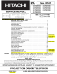
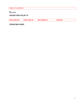
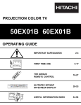
SCREEN OVERLAY
SCREEN OVERLAY (JIG)
Required for convergence alignments. See page 6 for installation procedure.
SCREEN
OVERLAY
Red
Horizontal
Offset
Horizontal Size m arks
R
Vertical
Size
m arks
Blue
Horizontal
Offset
B
Shown above is an example of the screen overlay (jig).
5
5/64”
(bottom of page #)
(right border)
(left border)
9/32”
9/32”
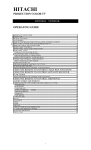
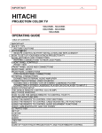
SCREEN OVERLAY
SCREEN
OVERLAY
SCREEN OVERLAY INSTALLATION
Must be used during a complete alignment
Spaced
Equally
R
B
Place the transparent Screen Overlay geometrically on the
PTV screen, making sure the outside lines on the overlay are
an equal distance from the inside edges of the frame on all
four sides.
6
5/64”
(bottom of page #)
(right border)
(left border)
9/32”
9/32”
CHASSIS/MODEL CROSS REFERENCE
Including Remotes and Overlay part numbers
1H MODELS
CHASSIS
AP53
CROSS
REFERENCE
AP53D
AP53DP
AP53P
AP62
AP62P
AP63
AP63B
AP73
AP74
MODEL
REMOTE
OVERLAY
46UX20B
46UX21K
50UX22B
50UX23K
60SX10B
60SX11K
60SX10BA
60SX11KA
46UX20BA
46UX21KA
50UX22BA
50UX23KA
50FX18B
50FX19K
50FX30B
55FX20B
60FX32B
50FX48B
46UX24B
46UX25K
50UX26B
50UX27K
60SX12B
60SX13K
46UX50B
46UX51K
50UX52B
50UX53K
60UX54B
60UX55K
50SBX70B
60SBX72B
70SBX74B
CLU-951MP
CLU-951MP
CLU-951MP
CLU-951MP
CLU-951MP
CLU-951MP
CLU-951MP
CLU-951MP
CLU-951MP
CLU-951MP
CLU-951MP
CLU-951MP
CLU-417UI
CLU-417UI
CLU-434VP
CLU-417UI
CLU-951MP
CLU-417UI
CLU-952MP
CLU-952MP
CLU-952MP
CLU-952MP
CLU-952MP
CLU-952MP
CLU-612MP
CLU-612MP
CLU-612MP
CLU-612MP
CLU-612MP
CLU-612MP
CLU-612MP
CLU-612MP
CLU-612MP
H310353
H310353
H310354
H310354
H310355
H310355
H310355
H310355
H310353
H310353
H310354
H310354
H310354
H310354
H310354
H310356
H310355
H310354
H310353
H310353
H310354
H310354
H310355
H310355
H310353
H310353
H310354
H310354
H310355
H310355
H310354
H310355
H310357
7
5/64”
(bottom of page #)
(right border)
(left border)
9/32”
9/32”
CHASSIS/MODEL CROSS REFERENCE
Including Remotes and Overlay part numbers
CHASSIS
MODEL
REMOTE
OVERLAY
AP82
55FX48B
50UX58B/K
55UX58BA
60UX58B/K
55UX58B
50UX57B
60UX57B
50SBX78B
60SBX78B
50GX49B
46FX01B
46GX01B
50GX10B
50GX20B
50GX10BA
50GX20BA
46GX01BA
53SBX59B
61SBX59B
53SBX01B
61SBX01B
43GX01B
50DX10B
50DX20B
50FX20B
60DX10B
60DX20B
60FX20B
43GX10B
50GX30B
50GX30BA
53SBX10B
CLU-431UI
CLU-612MP
CLU-612MP
CLU-612MP
CLU-612MP
CLU-615MP
CLU-615MP
CLU-613MP
CLU-613MP
CLU-435U
CLU-436UI
CLU-436UI
CLU-436UI
CLU-436UI
CLU-436UI
CLU-436UI
CLU-436UI
CLU-615MP
CLU-615MP
CLU-573TSI
CLU-573TSI
CLU-573TSI
CLU-4311UG
CLU-4311UG
CLU-4311UG
CLU-4311UG
CLU-4311UG
CLU-4311UG
CLU-4311UG
CLU-4311UG
CLU-4311UG
CLU-5714TSI
H310356
H310354
H310356
H310355
H310356
H310354
H310355
H310354
H310355
H310354
H310353
H310353
H310354
H310354
H310354
H310354
H310353
H310359
H310358
H310359
H310358
H312222
H310354
H310354
H310354
H310355
H310355
H310355
H312222
H310354
H310354
H310359
AP83
AP83P
AP83R
AP84
AP92
AP92R
AP92R/S
AP93
AP93R
AP02
HP11
HP12
HP13
CROSS
REFERENCE
1H MODELS
8
5/64”
(bottom of page #)
(right border)
(left border)
9/32”
9/32”
CHASSIS/MODEL CROSS REFERENCE
Including Remotes and Overlay part numbers
2H MODELS
CHASSIS
MODEL
DP85
61HDX98B
53SDX89B
60SDX88B
53SDX89BA
60SDX88BA
53FDX01B
43FDX01B
53SDX01B
61SDX01B
53SWX01W
61SWX01W
43UWX10B
53UWX10B
53UWX10BA
61UWX10B
61UWX10BA
53UDX10B
53UDX10BA
61UDX10B
43FDX10B
43FDX11B
53FDX20B
43FDX15B
43FDX20B
53SWX10B
53SWX12B
61SWX10B
61SWX12B
51UWX20B
57UWX20B
51/57F500
51/57G500
51GWX20B
57GWX20B
46F500
43FWX20B
57XWX20B
65XWX20B
51SWX20B
57SWX20B
65SWX20B
57TWX20B
65TWX20B
DP86
DP86V
CROSS
REFERENCE
DP05
DP05F
DP06
DP07
DP14G
DP15
DP15E
DP15H
DP15K
DP17
DP23
DP23G
DP23K
DP24
DP26
DP27
DP27D
REMOTE
OVERLAY 1 OVERLAY 2
CLU-614MP H312182A H312183A
CLU-615MP
H310359
H312184
CLU-612MP
H310355 H312181A
CLU-615MP
H310359
H312184
CLU-615MP
H310355 H312181A
CLU-575TSI
H312223
H312224
CLU-575TSI
H312225
H312226
CLU-572TSI
H312223
H312224
CLU-572TSI
H310355 H312181A
CLU-575TSI
H312241
H312242
CLU-575TSI
H312243
H312244
CLU-5713TSI H312259
CLU-5711TSI H312257
CLU-5711TSI H312257
CLU-5711TSI H312258
CLU-5711TSI H312258
CLU-5713TSI H312253
H312254
CLU-5713TSI H312253
H312254
CLU-5713TSI H312255
H312256
CLU-5713TSI H312251
H312252
CLU-5713TSI H312251
H312252
CLU-4322UG H312253
H312254
CLU-4322UG H312251
H312252
CLU-4322UG H312251
H312252
CLU-5713TSI H312257
CLU-5713TSI H312257
CLU-5713TSI H312258
CLU-5713TSI H312258
CLU-4321UG H312272
CLU-4321UG H312273
CLU-4321UG H312273
CLU-4321UG H312273
CLU-4321UG H312272
CLU-4321UG H312273
CLU-4321UG H312275
CLU-4321UG H312271
CLU-5721TSI H312273
CLU-5721TSI H312274
CLU-5722TSI H312272
CLU-5722TSI H312273
CLU-5722TSI H312274
CLU-5722TSI H312273
CLU-5722TSI H312274
9
5/64”
(bottom of page #)
(right border)
(left border)
9/32”
9/32”
Remote
CLU-951MP
CLU-952MP
Page
11
13
CLU-417UI
CLU-431UI
CLU-434VP
CLU-435U
CLU-436UI
15
17
19
21
23
CLU-612MP
CLU-613MP
CLU-614MP
CLU-615MP
CLU-617MP
25
27
29
31
33
CLU-572TSI
CLU-573TSI
CLU-575TSI
35
37
39
CLU-5711TSI
CLU-5712TSI
CLU-5713TSI
CLU-5714TSI
41
43
45
47
CLU-5721TSI
CLU-5722TSI
49
51
CLU-4311UG
CLU-4321UG
CLU-4322UG
53
55
57
REMOTES
REMOTE CONFIGURATIONS
10
5/64”
(bottom of page #)
(right border)
(left border)
9/32”
9/32”
REMOTE CONFIGURATIONS CLU-951MP
TV
POW ER
CABLE
V C R /A U D IO
RO M
Read
1
P IP
Calculate
SWAP
S H IFT
SRD
AI
FR Z
AN T
CBL
CBL
3
REMOTES
P hase
A djust
4
2
RO M
W rite
5
Centering
6
Initialize
T V /C A B L E
VCR
Rem ove
Color
A U D IO
7
9
M ENU
ENTER
C rosshatch
V ideo
8
VOL
CH
L S T -C H
C orrection
B uttons
M UTE
1
2
3
10
4
5
7
8
AVX
B LU E
13 x 9
RE D
7x5
6
9
RECALL
0
11
C ursor
P osition
B uttons
12
13
GR EE N
3x3
H ITAC H I
C LU -951M P
11
5/64”
(bottom of page #)
(right border)
(left border)
9/32”
9/32”
REMOTE CONFIGURATIONS CLU-951MP
1.
2.
3.
4.
5.
6.
7.
8.
9.
10.
11.
12.
13.
Read From ROM - Reads the stored EEPROM data
current working RAM. (PRESS 2X)
Write to ROM - Stores current convergence data in
working RAM to the EEPROM (PRESS 2X)
Phase Adjust - Mode used for matching positions of
the cursor and adjustment point for matching phase.
Calculate - Performs interpolation between adjustment
points for a total of 255 data locations.
Centering - Turns on the static raster centering mode
for matching the internal crosshatch to the external
video center.
Initialize - Develops the reference data for Magic Focus using the 8 sensors and light pattern sampling data.
(PRESS SHIFT, ANT)
Color Display Mode (Remove Color) - Used to toggle
between all colors (white) and either Green only, Red +
Green (yellow), or Blue + Green (cyan). Use of this
button is in conjunction with the AVX, 0, and RECALL buttons.
Correction Buttons - Used to adjust the horizontal and
vertical position of the adjustment point. The blinking
crosshatch intersection identifies the selected adjustment point.
Crosshatch/Video Mode - When pressed five times,
this button will toggle between the normal input video
and the internally generated convergence crosshatch
pattern.
Cursor Position Buttons - Moves the adjustment point
of the internal crosshatch pattern line intersections.
(2 = up, 4 = left, 5 = down, 6 = right)
Blue / 13 x 9 - When used with the MENU button, will
display green and blue. When pressed 5 times, will
enable 13 x 9 mode.
Red / 7 x 5 - When used with the MENU button, will
display green and red. When pressed 5 times, will enable 7 x 5 mode.
Green Only / 3 x 3 - When used with the MENU button, will display green only. When pressed 5 times, will
enable 3 x 3 mode, if RAM was cleared.
REMOTES
Button Explanations
12
5/64”
(bottom of page #)
(right border)
(left border)
9/32”
9/32”
REMOTE CONFIGURATIONS CLU-952MP
TV
POW ER
C AB LE
V C R /A U D IO
ROM
Read
1
P IP
ROM
W rite
5
Centering
MOVE
HOM E
TH EATER
P IP C H
FR Z
C A B LE
H E LP
T V /C A B L E
Initialize
REMOTES
2
SW AP
6
T V /C A B L E
VCR
Rem ove
Color
A U D IO
GRE EN
3x3
C
S
13
7
8
M EN U
E X IT
RECALL
VOL
CH
L S T -C H
C orrection
B uttons
M UTE
1
2
3
10
4
5
6
7
8
9
IN P U T
BLUE
13 x 9
RE D
7x5
C ursor
P osition
B uttons
SLEEP
0
11
12
H ITAC H I
C LU -952M P
13
5/64”
(bottom of page #)
(right border)
(left border)
9/32”
9/32”
REMOTE CONFIGURATIONS CLU-952MP
1.
2.
3.
4.
5.
6.
7.
8.
9.
10.
11.
12.
13.
Read From ROM - Reads the stored EEPROM data
current working RAM. (PRESS 2X)
Write to ROM - Stores current convergence data in
working RAM to the EEPROM (PRESS 2X)
Phase Adjust - Not Available
Calculate - Not Available
Centering - Turns on the static raster centering mode
for matching the internal crosshatch to the external
video center.
Initialize - Develops the reference data for Magic Focus using the 8 sensors and light pattern sampling data.
(PRESS MOVE, PIP CH)
Color Display Mode (Remove Color) - Used to toggle
between all colors (white) and either Green only, Red +
Green (yellow), or Blue + Green (cyan). Use of this
button is in conjunction with the INPUT, 0, and RECALL buttons.
Correction Buttons - Used to adjust the horizontal and
vertical position of the adjustment point. The blinking
crosshatch intersection identifies the selected adjustment point.
Crosshatch/Video Mode - Not Available
Cursor Position Buttons - Moves the adjustment point
of the internal crosshatch pattern line intersections.
(2 = up, 4 = left, 5 = down, 6 = right)
Blue / 13 x 9 - When used with the MENU button, will
display green and blue. When pressed 5 times, will
enable 13 x 9 mode.
Red / 7 x 5 - When used with the MENU button, will
display green and red. When pressed 5 times, will enable 7 x 5 mode.
Green Only / 3 x 3 - When used with the MENU button, will display green only. When pressed 5 times, will
enable 3 x 3 mode, if RAM was cleared.
REMOTES
Button Explanations
Note: It is not possible to adjust items 3, 4, and 9 using this
remote.
14
5/64”
(bottom of page #)
(right border)
(left border)
9/32”
9/32”
REMOTE CONFIGURATIONS CLU-417UI
POW ER
TV
C AB LE
VCR
H E LP
P IP C H
TV /V C R
REMOTES
P IP
S W AP M O V E
1
FR Z
2
5
C entering
R OM
R ead
R OM
W rite
REC
P AU S E
S TO P
R em ove
C olor
GR E EN
3x3
C
S
13
7
8
M ENU
E X IT
RECALL
VOL
CH
L S T -C H
C orrection
B uttons
M UTE
1
2
3
10
4
5
6
7
8
9
IN P U T
B LUE
13 x 9
R ED
7x5
C ursor
P osition
B uttons
SLEEP
0
11
12
H ITAC H I
C LU -417U I
15
5/64”
(bottom of page #)
(right border)
(left border)
9/32”
9/32”
REMOTE CONFIGURATIONS CLU-417UI
1.
2.
3.
4.
5.
6.
7.
8.
9.
10.
11.
12.
13.
Read From ROM - Reads the stored EEPROM data
current working RAM. (PRESS 2X)
Write to ROM - Stores current convergence data in
working RAM to the EEPROM (PRESS 2X)
Phase Adjust - Not Available
Calculate - Not Available
Centering - Turns on the static raster centering mode
for matching the internal crosshatch to the external
video center.
Initialize - Not Available
Color Display Mode (Remove Color) - Used to toggle
between all colors (white) and either Green only, Red +
Green (yellow), or Blue + Green (cyan). Use of this
button is in conjunction with the INPUT, 0, and RECALL buttons.
Correction Buttons - Used to adjust the horizontal and
vertical position of the adjustment point. The blinking
crosshatch intersection identifies the selected adjustment point.
Crosshatch/Video Mode - Not Available
Cursor Position Buttons - Moves the adjustment point
of the internal crosshatch pattern line intersections.
(2 = up, 4 = left, 5 = down, 6 = right)
Blue / 13 x 9 - When used with the MENU button, will
display green and blue. When pressed 5 times, will
enable 13 x 9 mode.
Red / 7 x 5 - When used with the MENU button, will
display green and red. When pressed 5 times, will enable 7 x 5 mode.
Green Only / 3 x 3 - When used with the MENU button, will display green only. When pressed 5 times, will
enable 3 x 3 mode, if RAM was cleared.
REMOTES
Button Explanations
Note: It is not possible to adjust items 3, 4, 6, and 9 using
this remote.
16
5/64”
(bottom of page #)
(right border)
(left border)
9/32”
9/32”
REMOTE CONFIGURATIONS CLU-431UI
POW ER
TV
C A B LE
VCR
H E LP
P IP C H
TV /V C R
REMOTES
3
P IP
P hase
A djust
SWAP M OVE
1
FR Z
2
5
Centering
RO M
Read
RO M
W rite
REC
P AU S E
S TO P
L S T -C H
Rem ove
Color
M UTE
VOL
CH
9
E X IT
GR EE N
3x3
RECALL
C .S .
C rosshatch
V ideo
7
FAV
CH
13
FAV
CH
M ENU
8
C orrection
B uttons
1
2
3
10
4
5
7
8
IN P U T
B LU E
13 x 9
RE D
7x5
C ursor
P osition
B uttons
6
9
SLEEP
0
11
12
H ITAC H I
C LU -431U I
17
5/64”
(bottom of page #)
(right border)
(left border)
9/32”
9/32”
REMOTE CONFIGURATIONS CLU-431UI
1.
2.
3.
4.
5.
6.
7.
8.
9.
10.
11.
12.
13.
Read From ROM - Reads the stored EEPROM data
current working RAM. (PRESS 2X)
Write to ROM - Stores current convergence data in
working RAM to the EEPROM (PRESS 2X)
Phase Adjust - Mode used for matching positions of
the cursor and adjustment point for matching phase.
Calculate - Not Available
Centering - Turns on the static raster centering mode
for matching the internal crosshatch to the external
video center.
Initialize - Not Available
Color Display Mode (Remove Color) - Used to toggle
between all colors (white) and either Green only, Red +
Green (yellow), or Blue + Green (cyan). Use of this
button is in conjunction with the INPUT, 0, and RECALL buttons.
Correction Buttons - Used to adjust the horizontal and
vertical position of the adjustment point. The blinking
crosshatch intersection identifies the selected adjustment point.
Crosshatch/Video Mode - When pressed five times,
this button will toggle between the normal input video
and the internally generated convergence crosshatch
pattern.
Cursor Position Buttons - Moves the adjustment point
of the internal crosshatch pattern line intersections.
(2 = up, 4 = left, 5 = down, 6 = right)
Blue / 13 x 9 - When used with the MENU button, will
display green and blue. When pressed 5 times, will
enable 13 x 9 mode.
Red / 7 x 5 - When used with the MENU button, will
display green and red. When pressed 5 times, will enable 7 x 5 mode.
Green Only / 3 x 3 - When used with the MENU button, will display green only. When pressed 5 times, will
enable 3 x 3 mode, if RAM was cleared.
REMOTES
Button Explanations
Note: It is not possible to adjust items 4 and 6 using this
remote.
18
5/64”
(bottom of page #)
(right border)
(left border)
9/32”
9/32”
REMOTE CONFIGURATIONS CLU-434VP
T V 8:43
RO M
Read
C AN C E L
AM
VCR +
R E V IE W
ENT ER
1
2
3
CLOCK
REMOTES
SW AP
1
C ursor
P osition
B uttons
10
ONC E
Centering
FR Z
5
4
5
8
6
D AIL Y
RO M
W rite
M OVE
7
W EE KLY
AD D T IM E
P IP
P IP C H
2
9
SE T UP
0
T V /V C R
12
POW E R
TV
C AB L E
VCR
LS T-C H
M UTE
CH
VOL
RE D
7x5
IN P U T
11
SL EEP
B LU E
13 x 9
R E C AL L /C S
13
E X IT
7
C orrection
B uttons
M EN U
HEL P
GR EE N
3x3
P L AY
8
REW
Rem ove
Color
F .F W D
ST OP
R EC
L IG H
PAU SE
T
H ITAC H I
V C R p lu
s+
C LU -434V P
19
5/64”
(bottom of page #)
(right border)
(left border)
9/32”
9/32”
REMOTE CONFIGURATIONS CLU-434VP
1.
2.
3.
4.
5.
6.
7.
8.
9.
10.
11.
12.
13.
Read From ROM - Reads the stored EEPROM data
current working RAM. (PRESS 2X)
Write to ROM - Stores current convergence data in
working RAM to the EEPROM (PRESS 2X)
Phase Adjust - Not Available
Calculate - Not Available
Centering - Turns on the static raster centering mode
for matching the internal crosshatch to the external
video center.
Initialize - Not Available
Color Display Mode (Remove Color) - Used to toggle
between all colors (white) and either Green only, Red +
Green (yellow), or Blue + Green (cyan). Use of this
button is in conjunction with the INPUT, 0, and RECALL buttons.
Correction Buttons - Used to adjust the horizontal and
vertical position of the adjustment point. The blinking
crosshatch intersection identifies the selected adjustment point.
Crosshatch/Video Mode - Not Available
Cursor Position Buttons - Moves the adjustment point
of the internal crosshatch pattern line intersections.
(2 = up, 4 = left, 5 = down, 6 = right)
Blue / 13 x 9 - When used with the MENU button, will
display green and blue. When pressed 5 times, will
enable 13 x 9 mode.
Red / 7 x 5 - When used with the MENU button, will
display green and red. When pressed 5 times, will enable 7 x 5 mode.
Green Only / 3 x 3 - When used with the MENU button, will display green only. When pressed 5 times, will
enable 3 x 3 mode, if RAM was cleared.
REMOTES
Button Explanations
Note: It is not possible to adjust items 3, 4, 6, and 9 using
this remote.
20
5/64”
(bottom of page #)
(right border)
(left border)
9/32”
9/32”
REMOTE CONFIGURATIONS CLU-435U
POW ER
TV
CA BLE
V CR
HE LP
C.C.
T V/VC R
REMOTES
3
P IP
P hase
A djust
S W A P MO VE
1
FRZ
2
5
Centering
RO M
Read
RO M
W rite
RE C
P AUS E
S TOP
L S T -C H
Rem ove
Color
M UTE
VOL
CH
9
E X IT
GR EE N
3x3
RECALL
C .S .
FAV
CH
13
FAV
CH
M ENU
8
1
C orrection
B uttons
2
3
10
4
5
7
8
IN P U T
B LU E
13 x 9
RE D
7x5
C rosshatch
V ideo
7
C ursor
P osition
B uttons
6
9
SLEEP
0
11
12
H ITAC H I
C LU -435U
21
5/64”
(bottom of page #)
(right border)
(left border)
9/32”
9/32”
REMOTE CONFIGURATIONS CLU-435U
1.
2.
3.
4.
5.
6.
7.
8.
9.
10.
11.
12.
13.
Read From ROM - Reads the stored EEPROM data
current working RAM. (PRESS 2X)
Write to ROM - Stores current convergence data in
working RAM to the EEPROM (PRESS 2X)
Phase Adjust - Mode used for matching positions of
the cursor and adjustment point for matching phase.
Calculate - Not Available
Centering - Turns on the static raster centering mode
for matching the internal crosshatch to the external
video center.
Initialize - Not Available
Color Display Mode (Remove Color) - Used to toggle
between all colors (white) and either Green only, Red +
Green (yellow), or Blue + Green (cyan). Use of this
button is in conjunction with the INPUT, 0, and RECALL buttons.
Correction Buttons - Used to adjust the horizontal and
vertical position of the adjustment point. The blinking
crosshatch intersection identifies the selected adjustment point.
Crosshatch/Video Mode - When pressed five times,
this button will toggle between the normal input video
and the internally generated convergence crosshatch
pattern.
Cursor Position Buttons - Moves the adjustment point
of the internal crosshatch pattern line intersections.
(2 = up, 4 = left, 5 = down, 6 = right)
Blue / 13 x 9 - When used with the MENU button, will
display green and blue. When pressed 5 times, will
enable 13 x 9 mode.
Red / 7 x 5 - When used with the MENU button, will
display green and red. When pressed 5 times, will enable 7 x 5 mode.
Green Only / 3 x 3 - When used with the MENU button, will display green only. When pressed 5 times, will
enable 3 x 3 mode, if RAM was cleared.
REMOTES
Button Explanations
Note: It is not possible to adjust items 4 and 6 using this
remote.
22
5/64”
(bottom of page #)
(right border)
(left border)
9/32”
9/32”
REMOTE CONFIGURATIONS CLU-436UI
POW ER
TV
C AB LE
VCR
H E LP
P IP C H
TV /V C R
REMOTES
3
P IP
S W AP M O V E
P hase
A djust
1
FR Z
2
5
C entering
R OM
R ead
R OM
W rite
REC
P AU S E
S TO P
R em ove
C olor
GR E EN
3x3
C
S
13
7
8
M ENU
E X IT
RECALL
VOL
CH
C orrection
B uttons
L S T -C H
M UTE
1
2
3
10
4
5
7
8
IN P U T
B LUE
13 x 9
R ED
7x5
C ursor
P osition
B uttons
6
9
SLEEP
0
11
12
H ITAC H I
C LU -436U I
23
5/64”
(bottom of page #)
(right border)
(left border)
9/32”
9/32”
REMOTE CONFIGURATIONS CLU-436UI
1.
2.
3.
4.
5.
6.
7.
8.
9.
10.
11.
12.
13.
Read From ROM - Reads the stored EEPROM data
current working RAM. (PRESS 2X)
Write to ROM - Stores current convergence data in
working RAM to the EEPROM (PRESS 2X)
Phase Adjust - Mode used for matching positions of
the cursor and adjustment point for matching phase.
Calculate - Not Available
Centering - Turns on the static raster centering mode
for matching the internal crosshatch to the external
video center.
Initialize - Not Available
Color Display Mode (Remove Color) - Used to toggle
between all colors (white) and either Green only, Red +
Green (yellow), or Blue + Green (cyan). Use of this
button is in conjunction with the INPUT, 0, and RECALL buttons.
Correction Buttons - Used to adjust the horizontal and
vertical position of the adjustment point. The blinking
crosshatch intersection identifies the selected adjustment point.
Crosshatch/Video Mode - Not Available
Cursor Position Buttons - Moves the adjustment point
of the internal crosshatch pattern line intersections.
(2 = up, 4 = left, 5 = down, 6 = right)
Blue / 13 x 9 - When used with the MENU button, will
display green and blue. When pressed 5 times, will
enable 13 x 9 mode.
Red / 7 x 5 - When used with the MENU button, will
display green and red. When pressed 5 times, will enable 7 x 5 mode.
Green Only / 3 x 3 - When used with the MENU button, will display green only. When pressed 5 times, will
enable 3 x 3 mode, if RAM was cleared.
REMOTES
Button Explanations
Note: It is not possible to adjust items 4, 6, and 9 using this
remote.
24
5/64”
(bottom of page #)
(right border)
(left border)
9/32”
9/32”
REMOTE CONFIGURATIONS CLU-612MP
POW ER
RO M
Read
RO M
W rite
REMOTES
TV
C AB L E
D SS
1
2
P IP
SW AP
MOVE
6
3
5
P IP C H
H EL P
FRZ
Centering
T V /C A B L E /D S S
Initialize
VCR
A U D IO
L S T -C H
P hase
A djust
VOL
CH
M UTE
Calculate
IN F O
E X IT
G U ID E
4
GR EE N
3x3
C rosshatch
V ideo
9
RECALL
C .S .
FAV
CH
13
M ENU
7
C orrection
B uttons
FAV
CH
8
Rem ove
Color
SVCS
SCHED
REC
SELECT
1
2
4
5
7
8
3
10
IN P U T
B LU E
13 x 9
RE D
7x5
11
C ursor
P osition
B uttons
6
9
SLEEP
0
12
H ITAC H I
C LU -612M P
25
5/64”
(bottom of page #)
(right border)
(left border)
9/32”
9/32”
REMOTE CONFIGURATIONS CLU-612MP
1.
2.
3.
4.
5.
6.
7.
8.
9.
10.
11.
12.
13.
Read From ROM - Reads the stored EEPROM data
current working RAM. (PRESS 2X)
Write to ROM - Stores current convergence data in
working RAM to the EEPROM (PRESS 2X)
Phase Adjust - Mode used for matching positions of
the cursor and adjustment point for matching phase.
Calculate - Performs interpolation between adjustment
points for a total of 255 data locations.
Centering - Turns on the static raster centering mode
for matching the internal crosshatch to the external
video center.
Initialize - Develops the reference data for Magic Focus using the 8 sensors and light pattern sampling data.
(PRESS MOVE, PIP CH)
Color Display Mode (Remove Color) - Used to toggle
between all colors (white) and either Green only, Red +
Green (yellow), or Blue + Green (cyan). Use of this
button is in conjunction with the INPUT, 0, and RECALL buttons.
Correction Buttons - Used to adjust the horizontal and
vertical position of the adjustment point. The blinking
crosshatch intersection identifies the selected adjustment point.
Crosshatch/Video Mode - When pressed five times,
this button will toggle between the normal input video
and the internally generated convergence crosshatch
pattern.
Cursor Position Buttons - Moves the adjustment point
of the internal crosshatch pattern line intersections.
(2 = up, 4 = left, 5 = down, 6 = right)
Blue / 13 x 9 - When used with the MENU button, will
display green and blue. When pressed 5 times, will
enable 13 x 9 mode.
Red / 7 x 5 - When used with the MENU button, will
display green and red. When pressed 5 times, will enable 7 x 5 mode.
Green Only / 3 x 3 - When used with the MENU button, will display green only. When pressed 5 times, will
enable 3 x 3 mode, if RAM was cleared.
REMOTES
Button Explanations
26
5/64”
(bottom of page #)
(right border)
(left border)
9/32”
9/32”
REMOTE CONFIGURATIONS CLU-613MP
POW ER
R OM
R ead
R OM
W rite
REMOTES
TV
CABLE
DSS
1
2
P IP
SW AP
MOVE
6
3
5
P IP C H
HELP
FRZ
C entering
T V /C A B L E /D S S
Initialize
VCR
A U D IO
L S T -C H
P hase
A djust
VOL
CH
M UTE
C alculate
IN F O
E X IT
G U ID E
4
GR E EN
3x3
C rosshatch
V ideo
9
RECALL
C .S .
FA V
CH
13
M ENU
7
C orrection
B uttons
FA V
CH
8
R em ove
C olor
SVCS
SCHED
REC
SELECT
1
2
4
5
7
8
C ursor
P osition
B uttons
3
10
IN P U T
B LUE
13 x 9
R ED
7x5
11
6
9
SLEEP
0
12
H ITAC H I TV l u s +
C LU -613M P
G U ID E
p
27
5/64”
(bottom of page #)
(right border)
(left border)
9/32”
9/32”
REMOTE CONFIGURATIONS CLU-613MP
1.
2.
3.
4.
5.
6.
7.
8.
9.
10.
11.
12.
13.
Read From ROM - Reads the stored EEPROM data
current working RAM. (PRESS 2X)
Write to ROM - Stores current convergence data in
working RAM to the EEPROM (PRESS 2X)
Phase Adjust - Mode used for matching positions of
the cursor and adjustment point for matching phase.
Calculate - Performs interpolation between adjustment
points for a total of 255 data locations.
Centering - Turns on the static raster centering mode
for matching the internal crosshatch to the external
video center.
Initialize - Develops the reference data for Magic Focus using the 8 sensors and light pattern sampling data.
(PRESS MOVE, PIP CH)
Color Display Mode (Remove Color) - Used to toggle
between all colors (white) and either Green only, Red +
Green (yellow), or Blue + Green (cyan). Use of this
button is in conjunction with the INPUT, 0, and RECALL buttons.
Correction Buttons - Used to adjust the horizontal and
vertical position of the adjustment point. The blinking
crosshatch intersection identifies the selected adjustment point.
Crosshatch/Video Mode - When pressed five times,
this button will toggle between the normal input video
and the internally generated convergence crosshatch
pattern.
Cursor Position Buttons - Moves the adjustment point
of the internal crosshatch pattern line intersections.
(2 = up, 4 = left, 5 = down, 6 = right)
Blue / 13 x 9 - When used with the MENU button, will
display green and blue. When pressed 5 times, will
enable 13 x 9 mode.
Red / 7 x 5 - When used with the MENU button, will
display green and red. When pressed 5 times, will enable 7 x 5 mode.
Green Only / 3 x 3 - When used with the MENU button, will display green only. When pressed 5 times, will
enable 3 x 3 mode, if RAM was cleared.
REMOTES
Button Explanations
28
5/64”
(bottom of page #)
(right border)
(left border)
9/32”
9/32”
REMOTE CONFIGURATIONS CLU-614MP
POW ER
RO M
Read
RO M
W rite
REMOTES
TV
C AB L E
S AT
1
2
D T V /SA T
P IP
SW AP
6
3
5
P IP C H
ANT
MOVE
Centering
T V /C A B L E /D S S
Initialize
VCR
A U D IO
L S T -C H
P hase
A djust
VOL
CH
M UTE
Calculate
IN F O
E X IT
G U ID E
4
GR EE N
3x3
C rosshatch
V ideo
9
USER
HELP
FAV
CH
13
M ENU
7
C orrection
B uttons
FAV
CH
8
Rem ove
Color
SVCS
SCHED
REC
SELECT
1
2
4
5
7
8
3
10
IN P U T
B LU E
13 x 9
RE D
7x5
11
C ursor
P osition
B uttons
6
9
C .S .
0
12
H ITAC H I
C LU -614M P
29
5/64”
(bottom of page #)
(right border)
(left border)
9/32”
9/32”
REMOTE CONFIGURATIONS CLU-614MP
1.
2.
3.
4.
5.
6.
7.
8.
9.
10.
11.
12.
13.
Read From ROM - Reads the stored EEPROM data
current working RAM. (PRESS 2X)
Write to ROM - Stores current convergence data in
working RAM to the EEPROM (PRESS 2X)
Phase Adjust - Mode used for matching positions of
the cursor and adjustment point for matching phase.
Calculate - Performs interpolation between adjustment
points for a total of 255 data locations.
Centering - Turns on the static raster centering mode
for matching the internal crosshatch to the external
video center.
Initialize - Develops the reference data for Magic Focus using the 8 sensors and light pattern sampling data.
(PRESS SWAP, PIP CH)
Color Display Mode (Remove Color) - Used to toggle
between all colors (white) and either Green only, Red +
Green (yellow), or Blue + Green (cyan). Use of this
button is in conjunction with the INPUT, 0, and USER
buttons.
Correction Buttons - Used to adjust the horizontal and
vertical position of the adjustment point. The blinking
crosshatch intersection identifies the selected adjustment point.
Crosshatch/Video Mode - When pressed five times,
this button will toggle between the normal input video
and the internally generated convergence crosshatch
pattern.
Cursor Position Buttons - Moves the adjustment point
of the internal crosshatch pattern line intersections.
(2 = up, 4 = left, 5 = down, 6 = right)
Blue / 13 x 9 - When used with the MENU button, will
display green and blue. When pressed 5 times, will
enable 13 x 9 mode.
Red / 7 x 5 - When used with the MENU button, will
display green and red. When pressed 5 times, will enable 7 x 5 mode.
Green Only / 3 x 3 - When used with the MENU button, will display green only. When pressed 5 times, will
enable 3 x 3 mode, if RAM was cleared.
REMOTES
Button Explanations
30
5/64”
(bottom of page #)
(right border)
(left border)
9/32”
9/32”
REMOTE CONFIGURATIONS CLU-615MP
POW ER
RO M
Read
RO M
W rite
REMOTES
TV
C AB L E
S AT
1
2
P IP
SW AP
MOVE
6
3
5
P IP C H
H EL P
FRZ
Centering
T V /C A B L E /S A T
Initialize
VCR
A U D IO
L S T -C H
P hase
A djust
VOL
CH
M UTE
Calculate
IN F O
E X IT
G U ID E
4
GR EE N
3x3
C rosshatch
V ideo
9
RECALL
C .S .
FAV
CH
13
M ENU
7
C orrection
B uttons
FAV
CH
8
Rem ove
Color
SVCS
SCHED
REC
SELECT
1
2
4
5
7
8
3
10
IN P U T
B LU E
13 x 9
RE D
7x5
11
C ursor
P osition
B uttons
6
9
SLEEP
0
12
H ITAC H I
C LU -615M P
31
5/64”
(bottom of page #)
(right border)
(left border)
9/32”
9/32”
REMOTE CONFIGURATIONS CLU-615MP
1.
2.
3.
4.
5.
6.
7.
8.
9.
10.
11.
12.
13.
Read From ROM - Reads the stored EEPROM data
current working RAM. (PRESS 2X)
Write to ROM - Stores current convergence data in
working RAM to the EEPROM (PRESS 2X)
Phase Adjust - Mode used for matching positions of
the cursor and adjustment point for matching phase.
Calculate - Performs interpolation between adjustment
points for a total of 255 data locations.
Centering - Turns on the static raster centering mode
for matching the internal crosshatch to the external
video center.
Initialize - Develops the reference data for Magic Focus using the 8 sensors and light pattern sampling data.
(PRESS MOVE, PIP CH)
Color Display Mode (Remove Color) - Used to toggle
between all colors (white) and either Green only, Red +
Green (yellow), or Blue + Green (cyan). Use of this
button is in conjunction with the INPUT, 0, and RECALL buttons.
Correction Buttons - Used to adjust the horizontal and
vertical position of the adjustment point. The blinking
crosshatch intersection identifies the selected adjustment point.
Crosshatch/Video Mode - When pressed five times,
this button will toggle between the normal input video
and the internally generated convergence crosshatch
pattern.
Cursor Position Buttons - Moves the adjustment point
of the internal crosshatch pattern line intersections.
(2 = up, 4 = left, 5 = down, 6 = right)
Blue / 13 x 9 - When used with the MENU button, will
display green and blue. When pressed 5 times, will
enable 13 x 9 mode.
Red / 7 x 5 - When used with the MENU button, will
display green and red. When pressed 5 times, will enable 7 x 5 mode.
Green Only / 3 x 3 - When used with the MENU button, will display green only. When pressed 5 times, will
enable 3 x 3 mode, if RAM was cleared.
REMOTES
Button Explanations
32
5/64”
(bottom of page #)
(right border)
(left border)
9/32”
9/32”
REMOTE CONFIGURATIONS CLU-617MP
POW ER
RO M
Read
RO M
W rite
REMOTES
TV
C AB L E
S AT
1
2
P IP
SW AP
MOVE
6
3
5
P IP C H
H EL P
FRZ
Centering
T V /C A B L E /S A T
Initialize
VCR
A U D IO
L S T -C H
P hase
A djust
VOL
CH
M UTE
Calculate
IN F O
E X IT
G U ID E
4
GR EE N
3x3
C rosshatch
V ideo
9
RECALL
C .S .
FAV
CH
13
M ENU
7
C orrection
B uttons
FAV
CH
8
Rem ove
Color
SVCS
SCHED
REC
SELECT
1
2
4
5
7
8
3
10
IN P U T
B LU E
13 x 9
RE D
7x5
11
C ursor
P osition
B uttons
6
9
SLEEP
0
12
H ITAC H I
C LU -617M P
33
5/64”
(bottom of page #)
(right border)
(left border)
9/32”
9/32”
REMOTE CONFIGURATIONS CLU-617MP
1.
2.
3.
4.
5.
6.
7.
8.
9.
10.
11.
12.
13.
Read From ROM - Reads the stored EEPROM data
current working RAM. (PRESS 2X)
Write to ROM - Stores current convergence data in
working RAM to the EEPROM (PRESS 2X)
Phase Adjust - Mode used for matching positions of
the cursor and adjustment point for matching phase.
Calculate - Performs interpolation between adjustment
points for a total of 255 data locations.
Centering - Turns on the static raster centering mode
for matching the internal crosshatch to the external
video center.
Initialize - Develops the reference data for Magic Focus using the 8 sensors and light pattern sampling data.
(PRESS MOVE, PIP CH)
Color Display Mode (Remove Color) - Used to toggle
between all colors (white) and either Green only, Red +
Green (yellow), or Blue + Green (cyan). Use of this
button is in conjunction with the INPUT, 0, and RECALL buttons.
Correction Buttons - Used to adjust the horizontal and
vertical position of the adjustment point. The blinking
crosshatch intersection identifies the selected adjustment point.
Crosshatch/Video Mode - When pressed five times,
this button will toggle between the normal input video
and the internally generated convergence crosshatch
pattern.
Cursor Position Buttons - Moves the adjustment point
of the internal crosshatch pattern line intersections.
(2 = up, 4 = left, 5 = down, 6 = right)
Blue / 13 x 9 - When used with the MENU button, will
display green and blue. When pressed 5 times, will
enable 13 x 9 mode.
Red / 7 x 5 - When used with the MENU button, will
display green and red. When pressed 5 times, will enable 7 x 5 mode.
Green Only / 3 x 3 - When used with the MENU button, will display green only. When pressed 5 times, will
enable 3 x 3 mode, if RAM was cleared.
REMOTES
Button Explanations
34
5/64”
(bottom of page #)
(right border)
(left border)
9/32”
9/32”
REMOTE CONFIGURATIONS CLU-572TSI
PO W E R
VCR
TV
CBL
SAT
S O U R C E W IZ A R D
AV1
DVD
AV2
REMOTES
1
AV3
2
3
4
5
6
7
8
9
10
C ursor
P osition
B uttons
P hase
A djust
0
SLEEP
RE D
7X5
LAST CH
12
B LU E
13 x 9
HELP
C.C.
INPUT
C orrection
B uttons
9
N
ME
EX
U
IT
8
VO L
CH
SELE C T
MU
Initialize
C.S.
3
11
7
Rem ove
Color
C rosshatch
V ideo
ASPECT
TE
RE
SVCS
CA
LL
SCHD
13
VCR PLUS+
GR EE N
3x3
G UIDE/TV
INFO
4
PIP
PIP CH
6
RO M
W rite
FREEZE
Calculate
5
PIP AC C ESS
PIP M O DE
2
PRO G
SW AP
1
Centering
TV/VCR
SLO W
RO M
Read
REC
HITACHI
CLU -572T SI
35
5/64”
(bottom of page #)
(right border)
(left border)
9/32”
9/32”
REMOTE CONFIGURATIONS CLU-572TSI
1.
2.
3.
4.
5.
6.
7.
8.
9.
10.
11.
12.
13.
Read From ROM - Reads the stored EEPROM data
current working RAM. (PRESS 2X)
Write to ROM - Stores current convergence data in
working RAM to the EEPROM (PRESS 2X)
Phase Adjust - Mode used for matching positions of
the cursor and adjustment point for matching phase.
Calculate - Performs interpolation between adjustment
points for a total of 255 data locations.
Centering - Turns on the static raster centering mode
for matching the internal crosshatch to the external
video center.
Initialize - Develops the reference data for Magic Focus using the 8 sensors and light pattern sampling data.
(PRESS PIP MODE, PIP CH)
Color Display Mode (Remove Color) - Used to toggle
between all colors (white) and either Green only, Red +
Green (yellow), or Blue + Green (cyan). Use of this
button is in conjunction with the INPUT, 0, and RECALL buttons.
Correction Buttons - Used to adjust the horizontal and
vertical position of the adjustment point. The blinking
crosshatch intersection identifies the selected adjustment point.
Crosshatch/Video Mode - When pressed five times,
this button will toggle between the normal input video
and the internally generated convergence crosshatch
pattern.
Cursor Position Buttons - Moves the adjustment point
of the internal crosshatch pattern line intersections.
(2 = up, 4 = left, 5 = down, 6 = right)
Blue / 13 x 9 - When used with the MENU button, will
display green and blue. When pressed 5 times, will
enable 13 x 9 mode.
Red / 7 x 5 - When used with the MENU button, will
display green and red. When pressed 5 times, will enable 7 x 5 mode.
Green Only / 3 x 3 - When used with the MENU button, will display green only. When pressed 5 times, will
enable 3 x 3 mode, if RAM was cleared.
REMOTES
Button Explanations
36
5/64”
(bottom of page #)
(right border)
(left border)
9/32”
9/32”
REMOTE CONFIGURATIONS CLU-573TSI
PO W E R
VCR
TV
CBL
SAT
S O U R C E W IZ A R D
AV1
DVD
REMOTES
1
C ursor
P osition
B uttons
P hase
A djust
AV2
AV3
2
3
4
5
6
7
8
9
10
0
SLEEP
RE D
7X5
LAST CH
12
B LU E
13 x 9
C rosshatch
V ideo
HELP
INPUT
C.S.
3
11
7
EX
U
IT
8
Rem ove
Color
Initialize
C orrection
B uttons
9
N
ME
VO L
CH
SELE C T
MU
TE
RE
SVCS
VCR PLUS+
CA
LL
13
SCHD
GR EE N
3x3
G UIDE/TV
INFO
4
PIP
PIP CH
6
RO M
W rite
FREEZE
Calculate
5
PIP AC C ESS
SW AP
M O VE
1
2
PRO G
Centering
TV/VCR
SLO W
RO M
Read
REC
HITACHI
CLU -573T SI
37
5/64”
(bottom of page #)
(right border)
(left border)
9/32”
9/32”
REMOTE CONFIGURATIONS CLU-573TSI
1.
2.
3.
4.
5.
6.
7.
8.
9.
10.
11.
12.
13.
Read From ROM - Reads the stored EEPROM data
current working RAM. (PRESS 2X)
Write to ROM - Stores current convergence data in
working RAM to the EEPROM (PRESS 2X)
Phase Adjust - Mode used for matching positions of
the cursor and adjustment point for matching phase.
Calculate - Performs interpolation between adjustment
points for a total of 255 data locations.
Centering - Turns on the static raster centering mode
for matching the internal crosshatch to the external
video center.
Initialize - Develops the reference data for Magic Focus using the 8 sensors and light pattern sampling data.
(PRESS MOVE, PIP CH)
Color Display Mode (Remove Color) - Used to toggle
between all colors (white) and either Green only, Red +
Green (yellow), or Blue + Green (cyan). Use of this
button is in conjunction with the INPUT, 0, and RECALL buttons.
Correction Buttons - Used to adjust the horizontal and
vertical position of the adjustment point. The blinking
crosshatch intersection identifies the selected adjustment point.
Crosshatch/Video Mode - When pressed five times,
this button will toggle between the normal input video
and the internally generated convergence crosshatch
pattern.
Cursor Position Buttons - Moves the adjustment point
of the internal crosshatch pattern line intersections.
(2 = up, 4 = left, 5 = down, 6 = right)
Blue / 13 x 9 - When used with the MENU button, will
display green and blue. When pressed 5 times, will
enable 13 x 9 mode.
Red / 7 x 5 - When used with the MENU button, will
display green and red. When pressed 5 times, will enable 7 x 5 mode.
Green Only / 3 x 3 - When used with the MENU button, will display green only. When pressed 5 times, will
enable 3 x 3 mode, if RAM was cleared.
REMOTES
Button Explanations
38
5/64”
(bottom of page #)
(right border)
(left border)
9/32”
9/32”
REMOTE CONFIGURATIONS CLU-575TSI
PO W E R
VCR
TV
CBL
SAT
S O U R C E W IZ A R D
AV1
DVD
AV2
REMOTES
1
AV3
2
3
4
5
6
7
8
9
10
C ursor
P osition
B uttons
P hase
A djust
0
SLEEP
RE D
7X5
LAST CH
12
B LU E
13 x 9
HELP
C.C.
INPUT
M
C orrection
B uttons
9
EX
U
EN
IT
8
VO L
CH
SELE C T
MU
Initialize
C.S.
3
11
7
Rem ove
Color
C rosshatch
V ideo
ASPECT
TE
RE
SVCS
VCR PLUS+
CA
LL
SCHD
13
GR EE N
3x3
G UIDE/TV
INFO
4
PIP
PIP CH
6
RO M
W rite
FREEZE
Calculate
5
PIP AC C ESS
PIP M O DE
2
PRO G
SW AP
1
Centering
TV/VCR
SLO W
RO M
Read
REC
HITACHI
CLU -575T SI
39
5/64”
(bottom of page #)
(right border)
(left border)
9/32”
9/32”
REMOTE CONFIGURATIONS CLU-575TSI
1.
2.
3.
4.
5.
6.
7.
8.
9.
10.
11.
12.
13.
Read From ROM - Reads the stored EEPROM data
current working RAM. (PRESS 2X)
Write to ROM - Stores current convergence data in
working RAM to the EEPROM (PRESS 2X)
Phase Adjust - Mode used for matching positions of
the cursor and adjustment point for matching phase.
Calculate - Performs interpolation between adjustment
points for a total of 255 data locations.
Centering - Turns on the static raster centering mode
for matching the internal crosshatch to the external
video center.
Initialize - Develops the reference data for Magic Focus using the 8 sensors and light pattern sampling data.
(PRESS PIP MODE, PIP CH)
Color Display Mode (Remove Color) - Used to toggle
between all colors (white) and either Green only, Red +
Green (yellow), or Blue + Green (cyan). Use of this
button is in conjunction with the INPUT, 0, and RECALL buttons.
Correction Buttons - Used to adjust the horizontal and
vertical position of the adjustment point. The blinking
crosshatch intersection identifies the selected adjustment point.
Crosshatch/Video Mode - When pressed five times,
this button will toggle between the normal input video
and the internally generated convergence crosshatch
pattern.
Cursor Position Buttons - Moves the adjustment point
of the internal crosshatch pattern line intersections.
(2 = up, 4 = left, 5 = down, 6 = right)
Blue / 13 x 9 - When used with the MENU button, will
display green and blue. When pressed 5 times, will
enable 13 x 9 mode.
Red / 7 x 5 - When used with the MENU button, will
display green and red. When pressed 5 times, will enable 7 x 5 mode.
Green Only / 3 x 3 - When used with the MENU button, will display green only. When pressed 5 times, will
enable 3 x 3 mode, if RAM was cleared.
REMOTES
Button Explanations
40
5/64”
(bottom of page #)
(right border)
(left border)
9/32”
9/32”
REMOTE CONFIGURATIONS CLU-5711TSI
POW ER
VCR
TV
CBL
S TB
S O U R C E W IZ A R D
AV1
DVD
REMOTES
1
C ursor
P osition
B uttons
P hase
A djust
AV2
AV3
2
3
4
5
6
7
8
9
10
RE D
7X5
0
SLEEP
LAST CH
12
B LU E
13 x 9
HELP
C.C.
ANT
PIX
3
11
7
N
ME
VO L
EX
U
C orrection
B uttons
9
IT
GR EE N
3x3
CH
SELE C T
Rem ove
Color
8
MU
SV
Initialize
C rosshatch
V ideo
ASPECT
VI
D
CS
VC
1
VI
D
RP
L
TE
US
+
ST
IN FO
4
2
AT
US
13
G
D
UI
SC
E/
HD
TV
VI
VI
D
D
5
4
V ID 3
PIP
PIP CH
FREEZE
Calculate
5
6
PIP AC C ESS
RO M
W rite
PIP M O DE
2
PRO G
RO M
Read
SW AP
1
TV/VCR
Centering
SLO W
REC
HITACHI
CLU -5711T SI
41
5/64”
(bottom of page #)
(right border)
(left border)
9/32”
9/32”
REMOTE CONFIGURATIONS CLU-5711TSI
1.
2.
3.
4.
5.
6.
7.
8.
9.
10.
11.
12.
13.
Read From ROM - Reads the stored EEPROM data
current working RAM. (PRESS 2X)
Write to ROM - Stores current convergence data in
working RAM to the EEPROM (PRESS 2X)
Phase Adjust - Mode used for matching positions of
the cursor and adjustment point for matching phase.
Calculate - Performs interpolation between adjustment
points for a total of 255 data locations.
Centering - Turns on the static raster centering mode
for matching the internal crosshatch to the external
video center.
Initialize - Develops the reference data for Magic Focus using the 8 sensors and light pattern sampling data.
(PRESS PIP MODE, PIP CH)
Color Display Mode (Remove Color) - Used to toggle
between all colors (white) and either Green only, Red +
Green (yellow), or Blue + Green (cyan). Use of this
button is in conjunction with the ANT, 0, and
STATUS buttons.
Correction Buttons - Used to adjust the horizontal and
vertical position of the adjustment point. The blinking
crosshatch intersection identifies the selected adjustment point.
Crosshatch/Video Mode - When pressed five times,
this button will toggle between the normal input video
and the internally generated convergence crosshatch
pattern.
Cursor Position Buttons - Moves the adjustment point
of the internal crosshatch pattern line intersections.
(2 = up, 4 = left, 5 = down, 6 = right)
Blue / 13 x 9 - When used with the MENU button, will
display green and blue. When pressed 5 times, will
enable 13 x 9 mode.
Red / 7 x 5 - When used with the MENU button, will
display green and red. When pressed 5 times, will enable 7 x 5 mode.
Green Only / 3 x 3 - When used with the MENU button, will display green only. When pressed 5 times, will
enable 3 x 3 mode, if RAM was cleared.
REMOTES
Button Explanations
42
5/64”
(bottom of page #)
(right border)
(left border)
9/32”
9/32”
REMOTE CONFIGURATIONS CLU-5712TSI
PO W ER
VCR
TV
CBL
STB
SO URCE W IZARD
AV1
DVD
REMOTES
1
C ursor
P osition
B uttons
P hase
A djust
AV2
AV3
2
3
4
5
6
7
8
9
10
0
SLEE P
RE D
7X5
LAST CH
12
B LU E
13 x 9
C rosshatch
V ideo
HELP
INPUT
PIX
3
11
7
ME
Rem ove
Color
Initialize
C orrection
B uttons
9
EX
NU
IT
8
VO L
CH
SEL EC T
MU
TE
ST
SVCS
VCR PLUS+
AT
US
13
SCHD
GR EE N
3x3
G UIDE/TV
INFO
4
PIP
PIP CH
6
RO M
W rite
FREEZ E
Calculate
5
PIP AC C ESS
PIP M O DE
2
PRO G
SW AP
1
Centering
TV/VCR
SLO W
RO M
Read
REC
HITACHI
CLU -5712T SI
43
5/64”
(bottom of page #)
(right border)
(left border)
9/32”
9/32”
REMOTE CONFIGURATIONS CLU-5712TSI
1.
2.
3.
4.
5.
6.
7.
8.
9.
10.
11.
12.
13.
Read From ROM - Reads the stored EEPROM data
current working RAM. (PRESS 2X)
Write to ROM - Stores current convergence data in
working RAM to the EEPROM (PRESS 2X)
Phase Adjust - Mode used for matching positions of
the cursor and adjustment point for matching phase.
Calculate - Performs interpolation between adjustment
points for a total of 255 data locations.
Centering - Turns on the static raster centering mode
for matching the internal crosshatch to the external
video center.
Initialize - Develops the reference data for Magic Focus using the 8 sensors and light pattern sampling data.
(PRESS PIP MODE, PIP CH)
Color Display Mode (Remove Color) - Used to toggle
between all colors (white) and either Green only, Red +
Green (yellow), or Blue + Green (cyan). Use of this
button is in conjunction with the INPUT, 0, and
STATUS buttons.
Correction Buttons - Used to adjust the horizontal and
vertical position of the adjustment point. The blinking
crosshatch intersection identifies the selected adjustment point.
Crosshatch/Video Mode - When pressed five times,
this button will toggle between the normal input video
and the internally generated convergence crosshatch
pattern.
Cursor Position Buttons - Moves the adjustment point
of the internal crosshatch pattern line intersections.
(2 = up, 4 = left, 5 = down, 6 = right)
Blue / 13 x 9 - When used with the MENU button, will
display green and blue. When pressed 5 times, will
enable 13 x 9 mode.
Red / 7 x 5 - When used with the MENU button, will
display green and red. When pressed 5 times, will enable 7 x 5 mode.
Green Only / 3 x 3 - When used with the MENU button, will display green only. When pressed 5 times, will
enable 3 x 3 mode, if RAM was cleared.
REMOTES
Button Explanations
44
5/64”
(bottom of page #)
(right border)
(left border)
9/32”
9/32”
REMOTE CONFIGURATIONS CLU-5713TSI
PO W E R
VCR
TV
CBL
S TB
S O U R C E W IZ A R D
CD
DVD
TA P E
REMOTES
1
C ursor
P osition
B uttons
P hase
A djust
2
3
4
5
6
7
8
9
10
0
SLEEP
RE D
7x5
LAST CH
12
C rosshatch
V ideo
HELP
C.C.
ANT
ASPECT
M O DE
3
11
7
B LU E
13 x 9
ME
EX
NU
9
C orrection
B uttons
IT
8
VO L
MU
SV
VI
D
TE
ST
CS
VC
1
VI
D
CH
SELE C T
Rem ove
Color
Initialize
AM P
RP
L
US
+
US
13
GU
IN FO
4
2
AT
ID
SC
VI
D
GR EE N
3x3
HD
TV
E/
VI
D
5
4
V ID 3
PIP
PIP CH
6
RO M
W rite
FREEZE
5
Calculate
PIP AC C ESS
PIP M O DE
2
SW AP
1
PRO G
TV/VCR
SLO W
Centering
RO M
Read
REC
HITACHI
CLU -5713TSI
45
5/64”
(bottom of page #)
(right border)
(left border)
9/32”
9/32”
REMOTE CONFIGURATIONS CLU-5713TSI
1.
2.
3.
4.
5.
6.
7.
8.
9.
10.
11.
12.
13.
Read From ROM - Reads the stored EEPROM data
current working RAM. (PRESS 2X)
Write to ROM - Stores current convergence data in
working RAM to the EEPROM (PRESS 2X)
Phase Adjust - Mode used for matching positions of
the cursor and adjustment point for matching phase.
Calculate - Performs interpolation between adjustment
points for a total of 255 data locations.
Centering - Turns on the static raster centering mode
for matching the internal crosshatch to the external
video center.
Initialize - Develops the reference data for Magic Focus using the 8 sensors and light pattern sampling data.
(PRESS PIP MODE, PIP CH)
Color Display Mode (Remove Color) - Used to toggle
between all colors (white) and either Green only, Red +
Green (yellow), or Blue + Green (cyan). Use of this
button is in conjunction with the ANT, 0, and
STATUS buttons.
Correction Buttons - Used to adjust the horizontal and
vertical position of the adjustment point. The blinking
crosshatch intersection identifies the selected adjustment point.
Crosshatch/Video Mode - When pressed five times,
this button will toggle between the normal input video
and the internally generated convergence crosshatch
pattern.
Cursor Position Buttons - Moves the adjustment point
of the internal crosshatch pattern line intersections.
(2 = up, 4 = left, 5 = down, 6 = right)
Blue / 13 x 9 - When used with the MENU button, will
display green and blue. When pressed 5 times, will
enable 13 x 9 mode.
Red / 7 x 5 - When used with the MENU button, will
display green and red. When pressed 5 times, will enable 7 x 5 mode.
Green Only / 3 x 3 - When used with the MENU button, will display green only. When pressed 5 times, will
enable 3 x 3 mode, if RAM was cleared.
REMOTES
Button Explanations
46
5/64”
(bottom of page #)
(right border)
(left border)
9/32”
9/32”
REMOTE CONFIGURATIONS CLU-5714TSI
PO W E R
VCR
TV
CBL
S TB
S O U R C E W IZ A R D
CD
DVD
TA P E
REMOTES
1
C ursor
P osition
B uttons
P hase
A djust
AM P
2
3
4
5
6
7
8
9
10
0
SLEEP
RE D
7x5
LAST CH
12
C rosshatch
V ideo
HELP
INPUT
PIX
3
11
B LU E
13 x 9
7
C orrection
B uttons
9
ME
EX
NU
IT
8
Rem ove
Color
VO L
MU
TE
A
ST
SVCS
Initialize
CH
SELE C T
VCR PLUS+
TU
GR EE N
3x3
S
13
SCHD
G UIDE/TV
INFO
4
PIP
PIP CH
6
RO M
W rite
FREEZE
5
Calculate
PIP AC C ESS
PIP M O DE
2
SW AP
1
PRO G
TV/VCR
SLO W
Centering
RO M
Read
REC
HITACHI
CLU -5714TSI
47
5/64”
(bottom of page #)
(right border)
(left border)
9/32”
9/32”
REMOTE CONFIGURATIONS CLU-5714TSI
1.
2.
3.
4.
5.
6.
7.
8.
9.
10.
11.
12.
13.
Read From ROM - Reads the stored EEPROM data
current working RAM. (PRESS 2X)
Write to ROM - Stores current convergence data in
working RAM to the EEPROM (PRESS 2X)
Phase Adjust - Mode used for matching positions of
the cursor and adjustment point for matching phase.
Calculate - Performs interpolation between adjustment
points for a total of 255 data locations.
Centering - Turns on the static raster centering mode
for matching the internal crosshatch to the external
video center.
Initialize - Develops the reference data for Magic Focus using the 8 sensors and light pattern sampling data.
(PRESS PIP MODE, PIP CH)
Color Display Mode (Remove Color) - Used to toggle
between all colors (white) and either Green only, Red +
Green (yellow), or Blue + Green (cyan). Use of this
button is in conjunction with the INPUT, 0, and
STATUS buttons.
Correction Buttons - Used to adjust the horizontal and
vertical position of the adjustment point. The blinking
crosshatch intersection identifies the selected adjustment point.
Crosshatch/Video Mode - When pressed five times,
this button will toggle between the normal input video
and the internally generated convergence crosshatch
pattern.
Cursor Position Buttons - Moves the adjustment point
of the internal crosshatch pattern line intersections.
(2 = up, 4 = left, 5 = down, 6 = right)
Blue / 13 x 9 - When used with the MENU button, will
display green and blue. When pressed 5 times, will
enable 13 x 9 mode.
Red / 7 x 5 - When used with the MENU button, will
display green and red. When pressed 5 times, will enable 7 x 5 mode.
Green Only / 3 x 3 - When used with the MENU button, will display green only. When pressed 5 times, will
enable 3 x 3 mode, if RAM was cleared.
REMOTES
Button Explanations
48
5/64”
(bottom of page #)
(right border)
(left border)
9/32”
9/32”
REMOTE CONFIGURATIONS CLU-5721TSI
PO W E R
VCR
TV
CBL
S TB
S O U R C E W IZ A R D
CD
DVD
TA P E
1
REMOTES
C ursor
P osition
B uttons
P hase
A djust
AM P
2
3
4
5
6
7
8
9
-
0
10
SLEEP
12
13
INFO
G UIDE
A/V NE T
AN T
GR EE N
3x3
AS PE CT
V IR TU
3
11
7
B LU E
13 x 9
ME
VO L
9
C rosshatch
V ideo
CH
8
MU
SV
VI
D
TE
LA
CS
ST
CH
SC
HD
VI
1
VI
D
4
2
RE D
7x5
IT
SELE C T
Rem ove
Color
Initialize
EX
NU
AL HD
V ID
4
D
5
C orrection
B uttons
V ID 3
PIP
PIP CH
6
RO M
W rite
FREEZE
5
Calculate*
PIP AC C ESS
PIP M O DE
2
SW AP
VIDEO
1
Centering
RO M
Read
REC
HITACHI
CLU -5721TSI
*Remote must be in VCR Mode
49
5/64”
(bottom of page #)
(right border)
(left border)
9/32”
9/32”
REMOTE CONFIGURATIONS CLU-5721TSI
1.
2.
3.
4.
5.
6.
7.
8.
9.
10.
11.
12.
13.
Read From ROM - Reads the stored EEPROM data
current working RAM. (PRESS 2X)
Write to ROM - Stores current convergence data in
working RAM to the EEPROM (PRESS 2X)
Phase Adjust - Mode used for matching positions of
the cursor and adjustment point for matching phase.
Calculate - Performs interpolation between adjustment
points for a total of 255 data locations.
Centering - Turns on the static raster centering mode
for matching the internal crosshatch to the external
video center.
Initialize - Develops the reference data for Magic Focus using the 8 sensors and light pattern sampling data.
(PRESS PIP MODE, PIP CH)
Color Display Mode (Remove Color) - Used to toggle
between all colors (white) and either Green only, Red +
Green (yellow), or Blue + Green (cyan). Use of this
button is in conjunction with the ANT, 0, and INFO
buttons.
Correction Buttons - Used to adjust the horizontal and
vertical position of the adjustment point. The blinking
crosshatch intersection identifies the selected adjustment point.
Crosshatch/Video Mode - When pressed five times,
this button will toggle between the normal input video
and the internally generated convergence crosshatch
pattern.
Cursor Position Buttons - Moves the adjustment point
of the internal crosshatch pattern line intersections.
(2 = up, 4 = left, 5 = down, 6 = right)
Blue / 13 x 9 - When used with the MENU button, will
display green and blue. When pressed 5 times, will
enable 13 x 9 mode.
Red / 7 x 5 - When used with the MENU button, will
display green and red. When pressed 5 times, will enable 7 x 5 mode.
Green Only / 3 x 3 - When used with the MENU button, will display green only. When pressed 5 times, will
enable 3 x 3 mode, if RAM was cleared.
REMOTES
Button Explanations
50
5/64”
(bottom of page #)
(right border)
(left border)
9/32”
9/32”
REMOTE CONFIGURATIONS CLU-5722TSI
PO W E R
VCR
TV
CBL
S TB
S O U R C E W IZ A R D
CD
DVD
TA P E
1
REMOTES
C ursor
P osition
B uttons
AM P
2
3
4
5
6
7
8
9
10
P hase
A djust
12
GR EE N
3x3
13
0
SLEEP
A/V NET
C.C.
ANT
INFO
ASPECT VIRTUAL HD
3
11
7
B LU E
13 x 9
ME
VO L
9
IT
C rosshatch
V ideo
CH
SELE C T
8
Rem ove
Color
MU
SV
Initialize
EX
NU
VI
D
CS
VC
R
1
VI
D
PL
TE
US
LA
+
ST
CH
SC
G
D
UI
4
2
RE D
7x5
E/
HD
TV
VI
VI
D
4
D
5
C orrection
B uttons
V ID 3
PIP
PIP CH
6
RO M
W rite
FREEZE
5
Calculate*
PIP AC C ESS
PIP M O DE
2
SW AP
VIDEO
1
Centering
RO M
Read
REC
HITACHI
CLU -5722TSI
*Remote must be in VCR Mode
51
5/64”
(bottom of page #)
(right border)
(left border)
9/32”
9/32”
REMOTE CONFIGURATIONS CLU-5722TSI
1.
2.
3.
4.
5.
6.
7.
8.
9.
10.
11.
12.
13.
Read From ROM - Reads the stored EEPROM data
current working RAM. (PRESS 2X)
Write to ROM - Stores current convergence data in
working RAM to the EEPROM (PRESS 2X)
Phase Adjust - Mode used for matching positions of
the cursor and adjustment point for matching phase.
Calculate - Performs interpolation between adjustment
points for a total of 255 data locations.
Centering - Turns on the static raster centering mode
for matching the internal crosshatch to the external
video center.
Initialize - Develops the reference data for Magic Focus using the 8 sensors and light pattern sampling data.
(PRESS PIP MODE, PIP CH)
Color Display Mode (Remove Color) - Used to toggle
between all colors (white) and either Green only, Red +
Green (yellow), or Blue + Green (cyan). Use of this
button is in conjunction with the ANT, 0, and INFO
buttons.
Correction Buttons - Used to adjust the horizontal and
vertical position of the adjustment point. The blinking
crosshatch intersection identifies the selected adjustment point.
Crosshatch/Video Mode - When pressed five times,
this button will toggle between the normal input video
and the internally generated convergence crosshatch
pattern.
Cursor Position Buttons - Moves the adjustment point
of the internal crosshatch pattern line intersections.
(2 = up, 4 = left, 5 = down, 6 = right)
Blue / 13 x 9 - When used with the MENU button, will
display green and blue. When pressed 5 times, will
enable 13 x 9 mode.
Red / 7 x 5 - When used with the MENU button, will
display green and red. When pressed 5 times, will enable 7 x 5 mode.
Green Only / 3 x 3 - When used with the MENU button, will display green only. When pressed 5 times, will
enable 3 x 3 mode, if RAM was cleared.
REMOTES
Button Explanations
52
5/64”
(bottom of page #)
(right border)
(left border)
9/32”
9/32”
REMOTE CONFIGURATIONS CLU-4311UG
POW ER
TV
CABLE
D V D /V C R
RO M
Read
SW AP
M OVE
1
2
P IP
RO M
W rite
FREEZE
REMOTES
P hase
A djust
Centering
5
P IP C H
HELP
M ENU
6
3
7
Initialize
Rem ove
Color
SELECT
8
M UTE
LAST CH
E X IT
C orrection
B uttons
9
VOL
C rosshatch
V ideo
C ursor
P osition
B uttons
B LU E
13 x 9
CH
1
2
3
4
5
6
7
8
9
INPU T
0
STATU S
11
12
13
10
REC
TV/VCR
RE D
7x5
GR EE N
3x3
PIX
HITACHI
CLU -4311UG
53
5/64”
(bottom of page #)
(right border)
(left border)
9/32”
9/32”
REMOTE CONFIGURATIONS CLU-4311UG
1.
2.
3.
4.
5.
6.
7.
8.
9.
10.
11.
12.
13.
Read From ROM - Reads the stored EEPROM data
current working RAM. (PRESS 2X)
Write to ROM - Stores current convergence data in
working RAM to the EEPROM (PRESS 2X)
Phase Adjust - Mode used for matching positions of
the cursor and adjustment point for matching phase.
Calculate - Not Available
Centering - Turns on the static raster centering mode
for matching the internal crosshatch to the external
video center.
Initialize - Develops the reference data for Magic Focus using the 8 sensors and light pattern sampling data.
(PRESS MOVE, PIP CH)
Color Display Mode (Remove Color) - Used to toggle
between all colors (white) and either Green only, Red +
Green (yellow), or Blue + Green (cyan). Use of this
button is in conjunction with the INPUT, 0, and
STATUS buttons.
Correction Buttons - Used to adjust the horizontal and
vertical position of the adjustment point. The blinking
crosshatch intersection identifies the selected adjustment point.
Crosshatch/Video Mode - When pressed five times,
this button will toggle between the normal input video
and the internally generated convergence crosshatch
pattern.
Cursor Position Buttons - Moves the adjustment point
of the internal crosshatch pattern line intersections.
(2 = up, 4 = left, 5 = down, 6 = right)
Blue / 13 x 9 - When used with the MENU button, will
display green and blue. When pressed 5 times, will
enable 13 x 9 mode.
Red / 7 x 5 - When used with the MENU button, will
display green and red. When pressed 5 times, will enable 7 x 5 mode.
Green Only / 3 x 3 - When used with the MENU button, will display green only. When pressed 5 times, will
enable 3 x 3 mode, if RAM was cleared.
REMOTES
Button Explanations
Note: It is not possible to adjust item 4 using this remote.
54
5/64”
(bottom of page #)
(right border)
(left border)
9/32”
9/32”
REMOTE CONFIGURATIONS CLU-4321UG
POW ER
TV
C B L /S A T
D V D /V C R
RO M
Read
SW AP
P IP M O D E
1
2
P IP
RO M
W rite
FREEZE
Centering
REMOTES
5
P IP C H
V ID E O
M ENU
6
7
Initialize
Rem ove
Color
SELECT
8
M UTE
LAST CH
E X IT
C orrection
B uttons
9
VOL
C rosshatch
V ideo
C ursor
P osition
B uttons
B LU E
13 x 9
1
2
3
4
5
6
7
8
9
AN T
0
INFO
11
12
13
10
VID 1
P hase
A djust
CH
VID 2
3
VID 3
GR EE N
3x3
VID 4
4
ASPECT VIRTUAL HD
REC
RE D
7x5
Calculate*
VID 5
HITACHI
CLU -4321UG
55
5/64”
(bottom of page #)
(right border)
(left border)
9/32”
9/32”
REMOTE CONFIGURATIONS CLU-4321UG
1.
2.
3.
4.
5.
6.
7.
8.
9.
10.
11.
12.
13.
Read From ROM - Reads the stored EEPROM data
current working RAM. (PRESS 2X)
Write to ROM - Stores current convergence data in
working RAM to the EEPROM (PRESS 2X)
Phase Adjust - Mode used for matching positions of
the cursor and adjustment point for matching phase.
Calculate - Performs interpolation between adjustment
points for a total of 255 data locations.
Centering - Turns on the static raster centering mode
for matching the internal crosshatch to the external
video center.
Initialize - Develops the reference data for Magic Focus using the 8 sensors and light pattern sampling data.
(PRESS PIP MODE, PIP CH)
Color Display Mode (Remove Color) - Used to toggle
between all colors (white) and either Green only, Red +
Green (yellow), or Blue + Green (cyan). Use of this
button is in conjunction with the ANT, 0, and INFO
buttons.
Correction Buttons - Used to adjust the horizontal and
vertical position of the adjustment point. The blinking
crosshatch intersection identifies the selected adjustment point.
Crosshatch/Video Mode - When pressed five times,
this button will toggle between the normal input video
and the internally generated convergence crosshatch
pattern.
Cursor Position Buttons - Moves the adjustment point
of the internal crosshatch pattern line intersections.
(2 = up, 4 = left, 5 = down, 6 = right)
Blue / 13 x 9 - When used with the MENU button, will
display green and blue. When pressed 5 times, will
enable 13 x 9 mode.
Red / 7 x 5 - When used with the MENU button, will
display green and red. When pressed 5 times, will enable 7 x 5 mode.
Green Only / 3 x 3 - When used with the MENU button, will display green only. When pressed 5 times, will
enable 3 x 3 mode, if RAM was cleared.
REMOTES
Button Explanations
56
5/64”
(bottom of page #)
(right border)
(left border)
9/32”
9/32”
REMOTE CONFIGURATIONS CLU-4322UG
POW ER
TV
C B L /S A T
D V D /V C R
RO M
Read
SW AP
P IP M O D E
1
2
P IP
RO M
W rite
FREEZE
REMOTES
P hase
A djust
Centering
5
P IP C H
HELP
M ENU
6
3
7
Initialize
Rem ove
Color
SELECT
8
M UTE
LAST CH
E X IT
C orrection
B uttons
9
VOL
C rosshatch
V ideo
C ursor
P osition
B uttons
B LU E
13 x 9
CH
1
2
3
4
5
6
7
8
9
AN T
0
STATU S
11
12
13
10
VID 1
VID 2
REC
VID 3
VID 4
ASPECT
M O DE
RE D
7x5
GR EE N
3x3
VID 5
HITACHI
CLU -4322UG
57
5/64”
(bottom of page #)
(right border)
(left border)
9/32”
9/32”
REMOTE CONFIGURATIONS CLU-4322UG
1.
2.
3.
4.
5.
6.
7.
8.
9.
10.
11.
12.
13.
Read From ROM - Reads the stored EEPROM data
current working RAM. (PRESS 2X)
Write to ROM - Stores current convergence data in
working RAM to the EEPROM (PRESS 2X)
Phase Adjust - Mode used for matching positions of
the cursor and adjustment point for matching phase.
Calculate - Not Available
Centering - Turns on the static raster centering mode
for matching the internal crosshatch to the external
video center.
Initialize - Develops the reference data for Magic Focus using the 8 sensors and light pattern sampling data.
(PRESS PIP MODE, PIP CH)
Color Display Mode (Remove Color) - Used to toggle
between all colors (white) and either Green only, Red +
Green (yellow), or Blue + Green (cyan). Use of this
button is in conjunction with the ANT, 0, and
STATUS buttons.
Correction Buttons - Used to adjust the horizontal and
vertical position of the adjustment point. The blinking
crosshatch intersection identifies the selected adjustment point.
Crosshatch/Video Mode - When pressed five times,
this button will toggle between the normal input video
and the internally generated convergence crosshatch
pattern.
Cursor Position Buttons - Moves the adjustment point
of the internal crosshatch pattern line intersections.
(2 = up, 4 = left, 5 = down, 6 = right)
Blue / 13 x 9 - When used with the MENU button, will
display green and blue. When pressed 5 times, will
enable 13 x 9 mode.
Red / 7 x 5 - When used with the MENU button, will
display green and red. When pressed 5 times, will enable 7 x 5 mode.
Green Only / 3 x 3 - When used with the MENU button, will display green only. When pressed 5 times, will
enable 3 x 3 mode, if RAM was cleared.
REMOTES
Button Explanations
Note: It is not possible to adjust item 4 using this remote.
58
5/64”
(bottom of page #)
(right border)
(left border)
9/32”
9/32”
SERVICE SOLUTIONS
Maintenance Performed
STK Replacement
Go to Magic Focus Operation
CRT Replacement
Go to Complete Convergence Procedure
Need to set Magnetic Centering
(After centering adjust, go to Magic Focus)
SERVICE
SOLUTIONS
Deflection PWB Replacement
Go to Complete Convergence Procedure
Need to set H / V size and position
(Re-use original DCU, if possible)
DCU Replacement
Go to Complete Convergence Procedure
Need to create new ROM data
59
5/64”
(bottom of page #)
(right border)
(left border)
9/32”
9/32”
First Time Convergence Assessment
Perform Magic Focus Operation
(page 61)
Touch-up Convergence Procedure
Green needs adjustment
Red needs adjustment
Blue needs adjustment
Write to ROM
Initialize Sensors
(page 62)
(page 63)
(page 67)
(page 71)
(page 72)
Complete Convergence Procedure
Clear RAM
Magnetic Centering
Horizontal and Vertical Size Adjustment
Static Centering
Phase Adjustment
Green 3 x 3 Mode
Green 7 x 5 Mode
Green 13 x 9 Mode
Red/Blue 3 x 3 Mode
Red/Blue 7 x 5 Mode
Red/Blue 13 x 9 Mode
Write to ROM
Initialize Sensors
(page 74)
(page 75)
(page 77)
(page 78)
(page 79)
(page 81)
(page 83)
(page 85)
(page 87)
(page 89)
(page 91)
(page 93)
(page 94)
DCU Error Codes
(page 95)
Special Procedures for 2H Models
DP-85
DP-86
DP-0x
DP-14G
DP-15 (all)
DP-17
DP-23/23G/23K/24
DP-26/27/27D
(page 97)
(page 99)
(page 100)
(page 103)
(page 109)
(page 121)
(page 127)
(page 133)
SERVICE
SOLUTIONS
SERVICE SOLUTIONS
60
5/64”
(bottom of page #)
(right border)
(left border)
9/32”
9/32”
MAGIC FOCUS OPERATION
P ress the M A G IC F O C U S button
O pera tio n
S u ccessful
O pera tio n
S u ccessful
No
C o nv ergen ce
E rrors
C o nv ergen ce
E rrors
O pera tio n
U n su ccessful
MAGIC FOCUS
OPERATION
"STATIC"
or "+"
Appears
DONE!
Perform
Touch-up
Adjustm ents
Error
Codes
After Com pleting
Convergence
Adjustm ents,
W rite to ROM
G o to
Diagnostic
Table
(page 95)
Verify
Convergence
Satifactory
Initialize
M AG IC
FO CUS
Sensors
Error
Codes
Initialization
Com plete
DONE!
61
5/64”
(bottom of page #)
(right border)
(left border)
9/32”
9/32”
TOUCH-UP ALIGNMENT
Green Needs Adjustment
Like Analog convergence, the green is used as the reference color. Green should be touched up only if it’s
out and both red and blue are aligned with each other.
Otherwise, there’s no way to know if the reference is
out or the other two colors are out. (it could happen)
When green needs alignment, the overlay should be
used to check the reference.
When completed with green touch-up AND the entire
crosshatch display is converged, proceed to Write to
ROM (page 71) and Initialize Sensors (page 72).
TOUCH-UP
ALIGNMENT
Proceed to the Green 13 x 9 Mode (page 85) portion
of the complete convergence procedure.
62
5/64”
(bottom of page #)
(right border)
(left border)
9/32”
9/32”
TOUCH-UP ALIGNMENT - RED
1. ENTER DCAM (Digital Convergence Adjustment
Mode) Default is 13 x 9 Mode.
AP-5x/AP-6x: Press service switch behind hole on front
panel for all AP-5x and AP-6x chassis. (Figure 1)
All Other Chassis: Press service switch on the Deflection
PWB. (Figure 2) or, for models built after 2000, to access the
DCAM without removing the front panel;
TOUCH-UP
ALIGNMENT
Procedure for Chassis DP14G, DP15, DP17:
1) Press the MAGIC FOCUS button on front panel.
2) While Magic Focus is running, press MAGIC FOCUS
button again to “stop”.
3) When “STOP” is displayed in OSD, press RECALL or
STATUS button on remote control.
4) The unit will now be in the DCAM.
Procedure for Chassis DP23/23G, DP24, DP26, DP27:
1) Press the MAGIC FOCUS button on front panel.
2) While Magic Focus is running, press MAGIC FOCUS
button again to “stop”.
3) When “STOP” is displayed in OSD, press INFO button
on remote control.
4) The unit will now be in the DCAM.
Procedure for Chassis DP06, DP07, HP13:
1) Press and hold the MAGIC FOCUS button on front
panel.
2) While the button is held down, the OSD will change
from “MAGIC FOCUS” to “CENTER MODE”, then to
“STATIC MODE”.
3) When “STATIC MODE” is displayed in OSD, press
INPUT or ANT button on remote control.
4) The unit will now be in the DCAM.
Procedure for Chassis DP05F, DP05, HP11, HP12:
1) Press and hold the DIGITAL ARRAY or
CONVERGENCE ADJUST button on front panel.
2) While the button is held down, then press the INPUT or
ANT button on remote control.
3) The unit will now be in the DCAM.
(continued)
63
5/64”
(bottom of page #)
(right border)
(left border)
9/32”
9/32”
TOUCH-UP ALIGNMENT - RED
Service A djustm ent
Figure 1
AV X
!
E N T ER
#
#
VOL
"
"
!
$
&
&
CH
"
"
POW ER
M AG IC
FO C U S
M EN U
%
%
Figure 2
(FR O N T V IEW )
R
G
B
FOC US
PA CK
DEFLECTION PW B
TOUCH-UP
ALIGNMENT
S ER VIC E
S W ITC H
SIGNAL PW B
2. SELECT COLOR TO BE ADJUSTED (RED)
Press the button on the remote associated with Color Display
Mode (Remove Color) , then press the button on the remote
associated with Red / 7 x 5.
example: MENU, 0
Display should now be Red and Green crosshatch lines only.
If it is all three colors, press the MENU button again to toggle
from all colors back to Red and Green only.
(continued)
64
5/64”
(bottom of page #)
(right border)
(left border)
9/32”
9/32”
TOUCH-UP ALIGNMENT - RED
3. Use the Cursor Position Buttons to navigate from a
selected adjustment point to another adjustment point.
The blinking or dashed lines of the crosshatch intersection identifies the selected adjustment point.
1
2
3
4
5
6
TOUCH-UP
ALIGNMENT
4. Press the Cursor Adjustment Buttons at the selected
adjustment points to align the red H /V lines with the
green H / V lines.
FAV
FAV
M ENU
CH
CH
SELECT
SELECT
(continued)
65
5/64”
(bottom of page #)
(right border)
(left border)
9/32”
9/32”
TOUCH-UP ALIGNMENT - RED
13 x 9 Adjustment Locations
TOUCH-UP
ALIGNMENT
After adjustment of Red, the lines should appear yellow, which is Red and Green together. When pressing
the MENU button to toggle back to all colors, all lines
should be white. Proceed to Write to ROM (page 71)
when all touch-up adjustments are completed.
Red and Green - Before Adjustment
Red and Green - After Adjustment
66
5/64”
(bottom of page #)
(right border)
(left border)
9/32”
9/32”
TOUCH-UP ALIGNMENT - BLUE
1. ENTER DCAM (Digital Convergence Adjustment
Mode) Default is 13 x 9 Mode.
AP-5x/AP-6x: Press service switch behind hole on front
panel for all AP-5x and AP-6x chassis. (Figure 1)
All Other Chassis: Press service switch on the Deflection
PWB. (Figure 2) or, for models built after 2000, to access the
DCAM without removing the front panel;
TOUCH-UP
ALIGNMENT
Procedure for Chassis DP14G, DP15, DP17:
1) Press the MAGIC FOCUS button on front panel.
2) While Magic Focus is running, press MAGIC FOCUS
button again to “stop”.
3) When “STOP” is displayed in OSD, press RECALL or
STATUS button on remote control.
4) The unit will now be in the DCAM.
Procedure for Chassis DP23/23G, DP24, DP26, DP27:
1) Press the MAGIC FOCUS button on front panel.
2) While Magic Focus is running, press MAGIC FOCUS
button again to “stop”.
3) When “STOP” is displayed in OSD, press INFO button
on remote control.
4) The unit will now be in the DCAM.
Procedure for Chassis DP06, DP07, HP13:
1) Press and hold the MAGIC FOCUS button on front
panel.
2) While the button is held down, the OSD will change
from “MAGIC FOCUS” to “CENTER MODE”, then to
“STATIC MODE”.
3) When “STATIC MODE” is displayed in OSD, press
INPUT or ANT button on remote control.
4) The unit will now be in the DCAM.
Procedure for Chassis DP05F, DP05, HP11, HP12:
1) Press and hold the DIGITAL ARRAY or
CONVERGENCE ADJUST button on front panel.
2) While the button is held down, then press the INPUT or
ANT button on remote control.
3) The unit will now be in the DCAM.
(continued)
67
5/64”
(bottom of page #)
(right border)
(left border)
9/32”
9/32”
TOUCH-UP ALIGNMENT - BLUE
Service A djustm ent
Figure 1
AV X
!
E N T ER
#
#
VOL
"
"
!
$
&
&
CH
"
"
POW ER
M AG IC
FO C U S
M EN U
%
%
Figure 2
(FR O N T V IEW )
R
G
B
FOC US
PA CK
DEFLECTION PW B
TOUCH-UP
ALIGNMENT
S ER VIC E
S W ITC H
SIGNAL PW B
2. SELECT COLOR TO BE ADJUSTED (BLUE)
Press the button on the remote associated with Color Display
Mode (Remove Color) , then press the button on the remote
associated with Blue / 13 x 9 .
example: MENU, INPUT
Display should now be Blue and Green crosshatch lines only.
If it is all three colors, press the MENU button again to toggle
from all colors back to Blue and Green only.
(continued)
68
5/64”
(bottom of page #)
(right border)
(left border)
9/32”
9/32”
TOUCH-UP ALIGNMENT - BLUE
3. Use the Cursor Position Buttons to navigate from a
selected adjustment point to another adjustment point.
The blinking or dashed lines of the crosshatch intersection identifies the selected adjustment point.
1
2
3
4
5
6
TOUCH-UP
ALIGNMENT
4. Press the Cursor Adjustment Buttons at the selected
adjustment points to align the blue H /V lines with the
green H / V lines.
FAV
FAV
M ENU
CH
CH
SELECT
SELECT
(continued)
69
5/64”
(bottom of page #)
(right border)
(left border)
9/32”
9/32”
TOUCH-UP ALIGNMENT - BLUE
13 x 9 Adjustment Locations
TOUCH-UP
ALIGNMENT
After adjustment of Blue, the lines should appear cyan,
which is Blue and Green together. When pressing the
MENU button to toggle back to all colors, all lines
should be white. Proceed to Write to ROM (page 71)
when all touch-up adjustments are completed.
Blue and Green - Before Adjustment
Blue and Green - After Adjustment
70
5/64”
(bottom of page #)
(right border)
(left border)
9/32”
9/32”
TOUCH-UP ALIGNMENT
WRITE TO ROM
When convergence is complete, write the new data to
ROM. Press the button on the remote associated with
Write to ROM twice.
Example 1: MOVE, MOVE
Example 2: PIP MODE, PIP MODE
The screen will blank for approx. 20 seconds. When
ROM WRITE is complete, green dots will appear on
the screen. At this point, pressing the MUTE button
will return to the crosshatch display.
1S T B U T T O N P R E S S
TOUCH-UP
ALIGNMENT
R O M W R ITE ?
2N D B UT TO N P R E S S
AP P R O X . 2 0 SE C O N DS
R O M W R IT E C O M P LE TE
(continued)
71
5/64”
(bottom of page #)
(right border)
(left border)
9/32”
9/32”
TOUCH-UP ALIGNMENT
INITIALIZE SENSORS
When WRITE TO ROM is complete, the Magic Focus Sensors need to be initialized. Press the button on
the remote associated with Write to ROM, then press
the button on the remote associated with Initialize.
Example 1: MOVE, PIP CH
Example 2: PIP MODE, PIP CH
1 S T B U TT O N P R E S S
TOUCH-UP
ALIGNMENT
R O M W R ITE?
2N D B U TT O N P R E S S
IN ITIA L
AP P R O X . 90 S E C O N D S
IN ITIALIZE C O M P L E TE
If error codes display after this step, see page 95.
72
5/64”
(bottom of page #)
(right border)
(left border)
9/32”
9/32”
COMPLETE ALIGNMENT
COMPLETE
ALIGNMENT
Clear RAM............................................
Magnetic Centering...............................
Horizontal and Vertical Size.................
Static Centering.....................................
Phase Adjustment..................................
Green 3 x 3 Mode..................................
Green 7 x 5 Mode..................................
Green 13 x 9 Mode................................
Red/Blue 3 x 3 Mode............................
Red/Blue 7 x 5 Mode............................
Red/Blue 13 x 9 Mode..........................
Write to ROM.......................................
Initialize Sensors...................................
74
75
77
78
79
81
83
85
87
89
91
93
94
73
5/64”
(bottom of page #)
(right border)
(left border)
9/32”
9/32”
COMPLETE ALIGNMENT
CLEAR RAM
COMPLETE
ALIGNMENT
To clear the DCU RAM, this is accomplished by holding down the service switch then powering on the set.
This will result in a display that has it’s convergence
completely uncorrected. Note that this is not necessarily a permanent condition. All the previous convergence settings that were stored in the ROM are still
there. The important thing to remember here is the difference between RAM (Random Access Memory) and
ROM (Read Only Memory). RAM is what the convergence output devices are using for an input at any given
time, and ROM is what data settings were actually
written to the EEPROM.
Example of uncorrected convergence crosshatch
74
5/64”
(bottom of page #)
(right border)
(left border)
9/32”
9/32”
COMPLETE ALIGNMENT
MAGNETIC CENTERING
After clearing the DCU RAM, the next step is to perform the magnetic centering for each CRT.
Using an external pattern generator, input a single
crosshatch pattern.
Apply the screen overlay. (page 6)
Display normal video.
Press the button on the remote associated with
Crosshatch/Video Mode five (5) times.
Example: EXIT (x5)
COMPLETE
ALIGNMENT
G
Cen terin g Mag net
Beam Fo rm ing Magn et
Beam Alignm ent Magnet
(continued)
75
5/64”
(bottom of page #)
(right border)
(left border)
9/32”
9/32”
COMPLETE ALIGNMENT
MAGNETIC CENTERING
R
R
R
Single
Crosshatch
Green
Centered
B
COMPLETE
ALIGNMENT
Using the CRT magnets (centering rings), align each
color as described in the diagrams below. The horizontal line (left/right) for each color should be aligned with
the center horizontal line of the overlay. The vertical
line (up/down) for each color should be positioned as
shown, which is offset. This is done so that the Convergence Output devices (STK’s) will operate in a
more efficient manner, thus preventing possible memory overload in the DCU and causing an error during
sensor initialization. For example, the Blue is offset to
the right because the Blue CRT is physically to the
right of center (Green).
Single
Crosshatch
Red
Centered
(offset)
B
Single
Crosshatch
Blue
Centered
(offset)
B
76
5/64”
(bottom of page #)
(right border)
(left border)
9/32”
9/32”
COMPLETE ALIGNMENT
Horizontal / Vertical Size Adjust
After the magnetic centering has been accomplished, the
master size adjustment should be checked, and adjusted if
necessary.
Apply the screen overlay. (page 6)
Clear the DCU RAM. (page 74)
Select Green Only
Press the button on the remote associated with Color Display Mode (Remove Color), then press the button on the
remote associated with Green Only / 3 x 3 .
Example: MENU, RECALL
COMPLETE
ALIGNMENT
Adjust horizontal and vertical size controls (usually located
on the Power/Deflection PWB) so that the raster size corresponds to the size marks on the overlay.
Vertical
Size
Marks
R
B
Horizontal
Size
Marks
77
5/64”
(bottom of page #)
(right border)
(left border)
9/32”
9/32”
COMPLETE ALIGNMENT
STATIC CENTERING
After the magnetic centering and size adjustments have been
verified, the Static Centering should then be adjusted. The
screen overlay should be in place, and the DCU RAM should
still be cleared.
Enter the Static Raster Centering Mode
Press the button on the remote associated with Centering.
Example: FREEZE
Two additional horizontal lines will appear, to indicate that
the set is now in the Static Raster Centering Mode.
Additional
H oriz. Lines
COMPLETE
ALIGNMENT
Additional
H oriz. Lines
To select Red or Blue, press the button on the remote associated with Color Display Mode (Remove Color), then press
the button on the remote associated with Red / 7 x 5 or Blue /
13 x 9.
Example: MENU, 0 (Red)
Example: MENU, INPUT (Blue)
Adjust each color using the Correction Buttons until the
center is a white cross.
After adjustment is complete, press the button on the remote
associated with Centering to exit from the Static Raster Centering Mode.
Example: FREEZE
78
5/64”
(bottom of page #)
(right border)
(left border)
9/32”
9/32”
COMPLETE ALIGNMENT
DCU PHASE ADJUST
Apply the screen overlay. (page 6)
Enter DCAM by either pressing the service only switch, or
by remote command. (see page 63)
Select Green Only
Press the button on the remote associated with Color Display Mode (Remove Color), then press the button on the
remote associated with Green Only / 3 x 3
Example: MENU, RECALL
Enter Phase Adjustment Mode
Press the button on the remote* associated with Phase Adjust.
Example: HELP
* Some remotes can not enter Phase Adjustment Mode.
COMPLETE
ALIGNMENT
NOTE: All 2H models built since 2000 (DP-0x, DP-1x,
and DP-2x) have data values for Phase Adjust. Refer to
pages 100 - 133 for specific 2H model data.
The point between the
bent lines represents
the Adjustment Point
location.
The broken line intersection represents the
center of the screen.
(continued)
79
5/64”
(bottom of page #)
(right border)
(left border)
9/32”
9/32”
COMPLETE ALIGNMENT
DCU PHASE ADJUST
Using the Correction Buttons on the remote, position the
bent lines so that they are aligned with the center of the
screen as shown below.
To exit from the Phase Adjustment Mode, press the button on
the remote associated with Phase Adjust.
Example: HELP
COMPLETE
ALIGNMENT
Matches external
video center
This assures that the
convergence adjustment
occurs precisely at the
selected cursor position.
80
5/64”
(bottom of page #)
(right border)
(left border)
9/32”
9/32”
COMPLETE ALIGNMENT
GREEN 3 x 3 Mode
The first step in making convergence corrections is to ensure that the Green crosshatch is matched to the overlay. If
the DCU RAM was cleared, it will be possible to enter the
3 x 3 mode. Otherwise, when entering into the DCAM, the
default mode will be 13 x 9, which is the touch-up mode.
Apply the screen overlay. (page 6)
Clear the DCU RAM. (page 74)
Ensure that all size and centering adjustments have been
performed correctly. (pages 75-80)
Select 3 x 3 Mode.
Press the button on the remote associated with Green
Only / 3 x 3 five (5) times.
Example: RECALL (x 5)
COMPLETE
ALIGNMENT
Select Green Only
Press the button on the remote associated with Color Display Mode (Remove Color), then press the button on the
remote associated with Green Only / 3 x 3
Example: MENU, RECALL
3 x 3 Mode = 9 Adjustment Points - Before Adjustment
(continued)
81
5/64”
(bottom of page #)
(right border)
(left border)
9/32”
9/32”
COMPLETE ALIGNMENT
GREEN 3 x 3 Mode
The intersection of the two (H and V) dashed lines represents
the selected adjustment point. Press the Correction Buttons
at the selected adjustment point to align with the horizontal
and vertical lines of the screen overlay.
Use the Cursor Position Buttons to navigate between adjustment points.
FAV
FAV
MENU
CH
CH
Correction
Buttons
SELECT
COMPLETE
ALIGNMENT
SELECT
Cursor
Position
Buttons
1
2
3
4
5
6
3 x 3 Mode = 9 Adjustment Points - After Adjustment
82
5/64”
(bottom of page #)
(right border)
(left border)
9/32”
9/32”
COMPLETE ALIGNMENT
GREEN 7 x 5 Mode
Select 7 x 5 mode.
Press the button on the remote associated with Red / 7 x 5
five (5) times.
Example: 0 (x 5)
Select Green Only
Press the button on the remote associated with Color Display Mode (Remove Color), then press the button on the
remote associated with Green Only / 3 x 3
Example: MENU, RECALL
Press the Correction Buttons (", !, ', () at the selected
adjustment points to align the display with the horizontal
and vertical lines of the screen overlay.
COMPLETE
ALIGNMENT
Use the Cursor Position Buttons (2, 4, 5, 6) to navigate
between the adjustment points.
7 x 5 Mode = 35 Adjustment Points - After Adjustment
(continued)
83
5/64”
(bottom of page #)
(right border)
(left border)
9/32”
9/32”
COMPLETE ALIGNMENT
GREEN 7 x 5 Mode
Perform Interpolation as needed to correct for ‘S’ distortion
between points. Interpolation is basically a mathematical
operation that reduces the distance between two points. This
will average the error between points to correct the bent or
curved lines. This should always be done while in the 7 x 5
mode.
NOTE: Some Remotes do not have the capability for performing this operation. See pages 11-58 to determine each
remote’s capabilities.
COMPLETE
ALIGNMENT
Example: INFO
Before Interpolation
After Interpolation
84
5/64”
(bottom of page #)
(right border)
(left border)
9/32”
9/32”
COMPLETE ALIGNMENT
GREEN 13 x 9 Mode
Select 13 x 9 mode.
Press the button on the remote associated with Blue / 13 x
9 five (5) times.
Example: INPUT (x 5)
Select Green Only
Press the button on the remote associated with Color Display Mode (Remove Color), then press the button on the
remote associated with Green Only / 3 x 3
Example: MENU, RECALL
Press the Correction Buttons (", !, ', () at the selected
adjustment points to align the display with the horizontal
and vertical lines of the screen overlay.
COMPLETE
ALIGNMENT
Use the Cursor Position Buttons (2, 4, 5, 6) to navigate
between the adjustment points. Return to the 7 x 5 mode as
necessary to perform interpolation calculation.
Note: At this point, the green crosshatch should be perfectly aligned with the overlay. If it is not, return to the 7 x
5 mode or, if necessary, the 3 x 3 mode to make required
adjustments, until it matches the overlay.
Do not continue until green matches the overlay!
13 x 9 Mode = 117 Adjustment Points - After Adjustment
85
5/64”
(bottom of page #)
(right border)
(left border)
9/32”
GREEN
COMPLETE
COMPLETE
ALIGNMENT
9/32”
86
5/64”
(bottom of page #)
(right border)
(left border)
9/32”
9/32”
COMPLETE ALIGNMENT
RED/BLUE 3 x 3 Mode
The next step in making convergence corrections is to ensure that the Red and the Blue crosshatch is matched to the
Green (which was matched to the overlay). If the DCU
RAM was cleared, it will be possible to enter the 3 x 3
mode. Otherwise, when entering into the DCAM, the default mode will be 13 x 9, which is the touch-up mode.
Select 3 x 3 Mode.
Press the button on the remote associated with Green
Only / 3 x 3 five (5) times.
Example: RECALL (x 5)
Select (Red and Green) or (Blue and Green)
Press the button on the remote associated with Color Display Mode (Remove Color), then press the button on the
remote associated with Red / 7 x 5, or Blue / 13 x 9.
COMPLETE
ALIGNMENT
Example: MENU, 0 (Red)
or,
MENU, INPUT (Blue)
Note: The following diagrams only show Red and Green.
First do one color completely, then the other. It makes no
difference which one is done first.
3 x 3 Mode = 9 Adjustment Points - Before Adjustment
(continued)
87
5/64”
(bottom of page #)
(right border)
(left border)
9/32”
9/32”
COMPLETE ALIGNMENT
RED/BLUE 3 x 3 Mode
The intersection of the two (H and V) dashed lines represents
the selected adjustment point. Press the Correction Buttons
at the selected adjustment point to align with the horizontal
and vertical lines of the screen overlay.
Use the Cursor Position Buttons to navigate between adjustment points.
FAV
FAV
MENU
CH
CH
Correction
Buttons
SELECT
COMPLETE
ALIGNMENT
SELECT
Cursor
Position
Buttons
1
2
3
4
5
6
3 x 3 Mode = 9 Adjustment Points - After Adjustment
88
5/64”
(bottom of page #)
(right border)
(left border)
9/32”
9/32”
COMPLETE ALIGNMENT
RED/BLUE 7 x 5 Mode
Select 7 x 5 mode.
Press the button on the remote associated with Red / 7 x 5
five (5) times.
Example: 0 (x 5)
Select (Red and Green) or (Blue and Green)
Press the button on the remote associated with Color Display Mode (Remove Color), then press the button on the
remote associated with Red / 7 x 5, or Blue / 13 x 9.
Example: MENU, 0 (Red)
or,
MENU, INPUT (Blue)
COMPLETE
ALIGNMENT
Press the Correction Buttons (", !, ', () at the selected
adjustment points to align the display with the horizontal
and vertical lines of the screen overlay.
Use the Cursor Position Buttons (2, 4, 5, 6) to navigate
between the adjustment points.
7 x 5 Mode = 35 Adjustment Points - After Adjustment
(continued)
89
5/64”
(bottom of page #)
(right border)
(left border)
9/32”
9/32”
COMPLETE ALIGNMENT
RED/BLUE 7 x 5 Mode
Perform Interpolation as needed to correct for ‘S’ distortion
between points. Interpolation is basically a mathematical
operation that reduces the distance between two points. This
will average the error between points to correct the bent or
curved lines. This should always be done while in the 7 x 5
mode.
NOTE: Some Remotes do not have the capability for performing this operation. See pages 11-58 to determine each
remote’s capabilities.
COMPLETE
ALIGNMENT
Example: INFO
Before Interpolation
After Interpolation
90
5/64”
(bottom of page #)
(right border)
(left border)
9/32”
9/32”
COMPLETE ALIGNMENT
RED/BLUE 13 x 9 Mode
Select 13 x 9 mode.
Press the button on the remote associated with Blue / 13 x
9 five (5) times.
Example: INPUT (x 5)
Select (Red and Green) or (Blue and Green)
Press the button on the remote associated with Color Display Mode (Remove Color), then press the button on the
remote associated with Red / 7 x 5, or Blue / 13 x 9.
Example: MENU, 0 (Red)
or,
MENU, INPUT (Blue)
COMPLETE
ALIGNMENT
Press the Correction Buttons (", !, ', () at the selected
adjustment points to align the display with the horizontal
and vertical lines of the screen overlay.
Use the Cursor Position Buttons (2, 4, 5, 6) to navigate
between the adjustment points. Return to the 7 x 5 mode as
necessary to perform interpolation calculation.
Note: At this point, the Red/Blue crosshatch should be perfectly aligned with the Green. If it is not, return to the 7 x 5
mode or, if necessary, the 3 x 3 mode to make required
adjustments, until it matches the Green.
13 x 9 Mode = 117 Adjustment Points - After Adjustment
91
5/64”
(bottom of page #)
(right border)
(left border)
9/32”
RED/BLUE
COMPLETE
COMPLETE
ALIGNMENT
9/32”
92
5/64”
(bottom of page #)
(right border)
(left border)
9/32”
9/32”
COMPLETE ALIGNMENT
WRITE TO ROM
When convergence is complete, write the new data to
ROM. Press the button on the remote associated with
Write to ROM twice.
Example 1: MOVE, MOVE
Example 2: PIP MODE, PIP MODE
The screen will blank for approx. 20 seconds. When
ROM WRITE is complete, green dots will appear on
the screen. At this point, pressing the MUTE button
will return to the crosshatch display.
1S T B U T T O N P R E S S
R O M W R ITE ?
COMPLETE
ALIGNMENT
2N D B UT TO N P R E S S
AP P R O X . 2 0 SE C O N DS
R O M W R IT E C O M P LE TE
(continued)
93
5/64”
(bottom of page #)
(right border)
(left border)
9/32”
9/32”
COMPLETE ALIGNMENT
INITIALIZE SENSORS
When WRITE TO ROM is complete, the Magic Focus Sensors need to be initialized. Press the button on
the remote associated with Write to ROM, then press
the button on the remote associated with Initialize.
Example 1: MOVE, PIP CH
Example 2: PIP MODE, PIP CH
1 S T B U TT O N P R E S S
COMPLETE
ALIGNMENT
R O M W R ITE?
2N D B U TT O N P R E S S
IN ITIA L
AP P R O X . 90 S E C O N D S
IN ITIALIZE C O M P L E TE
If error codes display after this step, see page 95.
94
5/64”
(bottom of page #)
(right border)
(left border)
9/32”
9/32”
DCU ERROR CODES
If an error code appears after Magic Focus operation or
during the Sensor Initialization procedure, refer to the
following table to determine the possible area at fault.
ERROR
CODE
1
ERROR
MESSAGE
APPLICATION
COUNTERMEASURE
Magic
Focus
Sensor
Initialize
X
X
DCU ERROR CODES
VF Error
Replace DCU
2
Connect 1
Darken outside light
Placement of Sensor
Is pattern hitting Sensor?
Check connections
Replace Sensor
Replace Sensor PWB
Sensor connections
Replace DCU
Adjustment check (H / V)
3
A/D Level
Same as Error Code 2
4
Overflow
Placement of Sensor
Adjustment check (H / V)
Conv. Amp Gain check*
5
Convergence
Same as Error Code 4
X
X
7
Operation
Same as Error Code 4
X
X
9
Connect 2
Same as Error Code 2
X
X
Noise
Input strong strength signal
Check conn. DCU/Sensor
X
X
Sync
Input strong strength signal
Input standard NTSC signal
X
X
10
11
X
X
X
X
* Check convergence yoke return resistor values
95
5/64”
(bottom of page #)
(right border)
(left border)
9/32”
9/32”
2H MODEL PROCEDURES
Most of the Hitachi 2H (HDTV capable) models require that additional procedures be performed. This is
due to the fact that the horizontal or vertical deflection
is manipulated in some way, to properly display the
input HDTV signal. (An example would be a 4:3 model
displaying a 1080i image, which is 16:9) On the older
2H models, (pre-2001) the additional procedure involves simply doing the entire convergence procedure a
second time, using a different overlay and engaging the
manipulated deflection mode. However, on the newer
2H models, there are other adjustments that need to be
performed before even starting the convergence correction procedures, such as DCU Character Set-up, and
DCU Pattern Set-up. These additional adjustments are
necessary because the same DCU is used in a multitude
of cabinet sizes and the light pattern must strike the
sensors correctly for Magic Focus to function as well as
the correct "wording" must be seen. Understand that
as this document is prepared, newer and/or more up to
date alignment information can be located on our website, http://www.hitachiserviceusa.com
2H MODEL
PROCEDURES
General 2H Model Information
96
5/64”
(bottom of page #)
(right border)
(left border)
9/32”
9/32”
2H MODEL PROCEDURES
DP-85 Procedures
The DP-85 has two convergence modes; Normal and
Smooth-Wide. Since the TV manipulates the horizontal deflection in Smooth Wide mode only, the technician must converge the unit in both Normal mode and
Smooth Wide mode. There are two different overlays
to be used. See page 9 for the actual part numbers.
Note: This unit has four modes; Normal, Full, Fill, and
Smooth-Wide. Normal, Full, and Fill are considered
equivalent modes when pertaining to convergence, as
only the Smooth-Wide mode manipulates the horizontal deflection by changing the linearity of the horizontal
deflection waveform.
To access Normal (or Full, or Fill) mode:
1.
2H MODEL
PROCEDURES
2.
3.
Input an NTSC signal via tuner, composite video,
or S-video.
Using the remote, press MENU > Preferences >
Screen Format > Normal.
Press the Service switch.
To access Smooth-Wide mode:
1.
2.
3.
Input an NTSC signal via tuner, composite video,
or S-video.
Using the remote, press MENU > Preferences >
Screen Format > Smooth-Wide.
Press the Service switch.
Proceed with Digital Convergence Adjustments. It is
highly recommended to perform the WRITE TO ROM
operation after completing the first of the two mode
convergence procedures, otherwise you will run the
risk of losing your stored data, if you attempt to engage
3 x 3 mode, which requires clearing the RAM.
(continued)
97
5/64”
(bottom of page #)
(right border)
(left border)
9/32”
9/32”
2H MODEL PROCEDURES
DP-85 Procedures
The DP-85 has an additional feature to be used during convergence that is unique to the Smooth-Wide mode. This is
due to the image being noticeably wider than the standard
image of the past. (The DP-85 was Hitachi’s first 2H 16:9
model) There is an additional mode or function that can be
used when making convergence corrections. This is called the
Extended Mode, and is entered by pressing the PIP CH button.
Normal
Mode
A
A
Extended
Mode
2H MODEL
PROCEDURES
B
B
C
A = Two additional Horizontal lines. Not used.
B = Two additional Vertical lines. These lines are used to
align to the overlay. The proper actual adjustment at the sides
will commonly be outside the viewing area of the screen, so
these additional lines are used. Note that when adjusting the
convergence at the sides, it may take a little longer than usual
to get the lines exactly on the grid of the overlay. It’s more
important that the lines are straight rather than precisely on
the grid. (specification is 1 ~ 2 mm)
C = The intersection of dotted lines now includes a solid upper and lower bar which will be either Red, Green, or Blue;
depending on which color is being adjusted. In the case of the
above example, it is showing green.
98
5/64”
(bottom of page #)
(right border)
(left border)
9/32”
9/32”
2H MODEL PROCEDURES
DP-86 Procedures
The DP-86 has two convergence modes; Normal (or
Progressive) and HD (or High Definition). Since the
TV manipulates the horizontal deflection in HD mode
by increasing the scanning frequency (from 31.5 KHz
to 33.75 KHz), the technician must converge the unit in
both Normal mode and HD mode. There are two different overlays to be used. See page 9 for the actual part
numbers.
To access Normal (or Progressive) mode:
1.
2.
Input an NTSC signal via tuner, composite video,
or S-video.
Press the Service switch.
To access HD mode:
2H MODEL
PROCEDURES
1.
2.
Input an ATSC signal of 1080i at the component
input connections.
Press the Service switch.
Proceed with Digital Convergence Adjustments. It is
highly recommended to perform the WRITE TO ROM
operation after completing the first of the two mode
convergence procedures, otherwise you will run the
risk of losing your stored data, if you attempt to engage
3 x 3 mode, which requires clearing the RAM.
99
5/64”
(bottom of page #)
(right border)
(left border)
9/32”
9/32”
2H MODEL PROCEDURES
DP-0x Procedures
The DP-0x has two convergence modes; Normal (or
Progressive) and HD (or High Definition). Since the
TV manipulates the horizontal deflection in HD mode,
the technician must converge the unit in both Normal
mode and HD mode. There are two different overlays
to be used. See page 9 for the actual part numbers.
Note 1: The DP-05F does not have the Magic Focus
feature, therefore it is unnecessary to initialize the
Magic Focus Sensors. (there are none).
Note 3: There are two adjustments which are unique to
the DP-0x series; they are DCU PHASE ADJUST and
HORIZONTAL POSITION ADJUST. These must be
properly adjusted before starting the convergence correction adjustments.
2H MODEL
PROCEDURES
Note 2: The 61” DP-06 (61SDX01B) does not have it’s
own 61” overlays. Use the part number shown on page
9, which happens to be the same 60” overlay used on
the previous years model 60SDX88B. Center the overlay on the screen; there will be a 0.5” gap around the
overlay.
DCU PHASE ADJUST
Normal (Progressive) Mode
1. Input an NTSC signal via tuner, composite video,
or S-video.
2. Press the Service switch.
3. Press HELP button on remote. (Green crosshatch
is displayed)
4. Press EXIT button on remote. (Character pattern is
displayed, which is the DCU Phase setting mode)
5. Set PH-H phase data as shown below by using the
4 and 6 button on the remote.
6. Set PH-V phase data as shown below by using the
2 and 5 button on the remote.
(continued)
100
5/64”
(bottom of page #)
(right border)
(left border)
9/32”
9/32”
2H MODEL PROCEDURES
DP-0x Procedures
7.
Set CR-H phase data as shown below by using the
' and ( button on the remote.
8. Set CR-V phase data as shown below by using the
" and ! button on the remote.
9. Press HELP button on remote to exit from PHASE
ADJUST Mode.
10. Press PIP MODE button on remote twice to write
the new Phase data to memory.
11. When Green dots appear, press MUTE button on
remote to return to DCU adjustment mode.
DCU PHASE ADJUST
HD Mode
1. Input an ATSC signal of 1080i at the component
input connections.
2. Repeat steps 2 - 11 above.
2H MODEL
PROCEDURES
N O R M AL M O D E
HD MODE
PHASE M ODE
PHASE M O DE
PH-H: BB
PH-H: BB
PH-V: 0C
PH-V: 07
CR-H: 4C
CR-H: 4C
CR-V: 00
CR-V: 0C
(continued)
101
5/64”
(bottom of page #)
(right border)
(left border)
9/32”
9/32”
2H MODEL PROCEDURES
HORIZONTAL POSITION ADJUST
Normal (Progressive) Mode
1. Input an NTSC circle pattern test signal.
2. Ensure that the screen format is PROGRESSIVE.
3. Enter the I2C Bus alignment menu and select Item H
POSI on Page 2 of Service Menu.
4. Adjust the data so that the left and right hand sides are
equal.
5. Press the MENU button to exit from the Service Menu.
HORIZONTAL POSITION ADJUST
HD Mode
1. Input an ATSC 1080i circle pattern test signal.
2. Ensure that the screen format is HD.
3. Enter the I2C Bus alignment menu and select Item H
POSI on Page 2 of Service Menu
4. Adjust the data so that the left and right hand sides are
equal.
5. Press the MENU button to exit from the Service Menu.
Service Menu access and how to view/change the I2C Data
values:
PAGE 02
•The Set should be OFF
•Press and hold the INPUT but- TA 1300 NTSC
ton on the front panel.
H POSI
30
•Then press the POWER button.
FLEX CONT
•Release both buttons.
VD-POS
3F
2
•The Service Menu (I C) should
UPD64081
appear on the screen.
•To scroll through the Menu use
DYGA
09
the " and ! buttons.
DCGA
06
•To jump through the Service
VAPGA
05
Menu page by page, press the
VAPIN
0B
MENU button on Remote.
•To Adjust Data Values, use the
YHCOR
00
' and ( buttons.
Note: Value shown may or may not be typical
After making DCU Phase Adjustment and Horizontal Position Adjustment, proceed with convergence correction adjustments.
2H MODEL
PROCEDURES
DP-0x Procedures
102
5/64”
(bottom of page #)
(right border)
(left border)
9/32”
9/32”
2H MODEL PROCEDURES
DP-14G Procedures
The DP-14G has only one deflection mode however,
there are two adjustments which must be properly adjusted before starting the convergence correction adjustments; they are DCU PHASE ADJUST and HORIZONTAL POSITION ADJUST.
2H MODEL
PROCEDURES
DCU PHASE ADJUST
1. Input an NTSC signal via tuner, composite video,
or S-video.
2. Press the Service switch.
3. Press HELP button on remote. (Green crosshatch
is displayed)
4. Press EXIT button on remote. (Character pattern is
displayed, which is the DCU Phase setting mode)
5. Set PH-H phase data as shown below by using the
4 and 6 button on the remote.
6. Set PH-V phase data as shown below by using the
2 and 5 button on the remote.
7. Set CR-H phase data as shown below by using the
' and ( button on the remote.
8. Set CR-V phase data as shown below by using the
" and ! button on the remote.
9. Press HELP button on remote to exit from PHASE
ADJUST Mode.
10. Press PIP MODE button on remote twice to write
the new Phase data to memory.
11. When Green dots appear, press MUTE button on
remote to return to DCU adjustment mode.
PHASE MODE
PH-H: BF
PH-V: 07
CR-H: 4C
CR-V: 0C
(continued)
103
5/64”
(bottom of page #)
(right border)
(left border)
9/32”
9/32”
2H MODEL PROCEDURES
DP-14G Procedures
Service Menu access and how to view/change the
I2C Data values:
(PAGE 01)
•The Set should be OFF
•Press and hold the INPUT ADJUST MODE
!
SERVICE
button on the front panel.
•Then press the POWER but- SUB BRT
!
ton.
!
WHITE BAL
•Release both buttons.
R DRV (COOL)
3F
•The Service Menu (I2C)
B
DRV
(COOL)
3F
should appear on the screen.
80
•To scroll through the Menu R CUTOFF (COOL)
use the " and ! buttons.
G CUTOFF (COOL)
80
•To jump through the Service B CUTOFF (COOL)
80
Menu page by page, press the
H POSITION
3F
MENU button on Remote.
V
POSITION
3F
•To Adjust Data Values, use
the ' and ( buttons.
!
FACT RESET
2H MODEL
PROCEDURES
HORIZONTAL POSITION ADJUST
1. Input an NTSC crosshair signal.
2. Press the Service switch to change to internal DCU
crosshatch.
3. Mark the center of the DCU crosshatch with your
finger.
4. Enter the I2C Bus alignment menu and select Item
H POSI.
5. Adjust the data so that the center of NTSC crosshair matches the location found in step 3 above.
6. Press the MENU button to exit from the Service
Menu.
Note: Value shown may or may not be typical
After making DCU Phase Adjustment and Horizontal
Position Adjustment, proceed with convergence correction adjustments.
(continued)
104
5/64”
(bottom of page #)
(right border)
(left border)
9/32”
9/32”
2H MODEL PROCEDURES
DP-14G Procedures
There are two additional adjustments which must be
performed when replacing a DCU. These are called
DCU Character Set-up, and DCU Pattern Set-up.
These adjustments must be performed prior to making
convergence corrections.
DCU Character Set-up
1.
2.
3.
4.
5.
6.
2H MODEL
PROCEDURES
7.
8.
Connect NTSC signal.
Clear RAM. (page 74)
Press FREEZE button on remote. (two additional
horizontal lines will appear)
Press PIP CH button on remote. ADJ PARAMETER mode will now be displayed.
Press " or ! button to scroll through the table.
Press ' or ( button to change the data so that it
corresponds to the table shown below.
Press PIP MODE button twice to write the data to
the EEPROM.
When Green dots appear, press MUTE button on
remote to return to DCU adjustment mode.
ADJ. PARAMETER
ROM WRITE?
ADJ. DISP
77
SEL. STAT
00
DEMO WAIT
2F
(continued)
105
5/64”
(bottom of page #)
(right border)
(left border)
9/32”
9/32”
2H MODEL PROCEDURES
DP-14G Procedures
DCU Character Set-up Table
Normal
77
00
DEMO WAIT
INT STEP 1
2F
02
INT A DLY
INT C DLY
INT BAR
MGF STEP 1
0A
FA
1C
00
MGF A DLY
MGF C DLY
0A
FA
MGF BAR
SENSOR CK
SENSOR 0
SENSOR 1
SENSOR 2
SENSOR 3
0E
00
FF
00
FF
01
SENSOR 4
FF
SENSOR 5
SENSOR 6
SENSOR 7
AD LEVEL
E. DISPLAY
06
FF
07
03
00
ADJ. TIMS
AD LEVEL
AD NOISE
PHASE MOT
H. BLK-RV
H. BLK-GV
H. BLK-BV
60
05
80
60
03
01
03
H. BLK-H
PON DELAY
IR-CODE
INITIAL 50
MGF 50
9 POINT 50
STAT 50
00
0C
00
9E
96
FE
FE
DYNA 50
9F
2H MODEL
PROCEDURES
Parameter
ADJ.DISP
SEL. STAT
(continued)
106
5/64”
(bottom of page #)
(right border)
(left border)
9/32”
9/32”
2H MODEL PROCEDURES
DP-14G Procedures
DCU Pattern Set-up
1.
2.
3.
4.
5.
6.
Connect NTSC signal.
Clear RAM. (page 74)
Press FREEZE button on remote. (two additional
horizontal lines will appear)
Press HELP button on remote. Magic Focus Pattern Mode will now be displayed.
Press the 6 button to rotate the arrow. (Arrow indicates each sensor position)
Press the buttons shown below to switch colors.
STATUS = Green
0 = Red
ANT = Blue
2H MODEL
PROCEDURES
Press ' or ( button to change the data so that it
corresponds to the table shown below.
8. Press " or ! button to scroll vertically (RH, !,
RV, for example).
9. Press PIP MODE button twice to write the data to
the EEPROM.
10. When Green dots appear, press MUTE button on
remote to return to DCU adjustment mode.
7.
(continued)
107
5/64”
(bottom of page #)
(right border)
(left border)
9/32”
9/32”
2H MODEL PROCEDURES
DP-14G Procedures
DCU Pattern Set-up Tables
0
1
2
7
RH : 02
RV : FF
3
6
5
4
0
1
2
3
4
5
6
7
RH
02
02
FA
FE
FC
02
04
02
RV
00
00
03
00
FE
01
01
00
GH
02
02
FA
FE
FC
00
04
02
GV
00
00
03
00
FE
01
01
00
BH
04
FE
FC
FE
FA
FE
04
02
BV
03
00
01
00
00
01
FE
00
2H MODEL
PROCEDURES
43UWX10B ONLY
53UWX10B / 61UWX10B
0
1
2
3
4
5
6
7
RH
02
02
FA
FE
FC
02
04
02
RV
00
00
03
00
FE
01
01
00
GH
04
00
FE
FE
FE
00
04
02
GV
02
00
03
00
00
01
00
00
BH
04
FE
FC
FE
FA
FE
04
02
BV
03
00
01
00
00
01
FE
00
108
5/64”
(bottom of page #)
(right border)
(left border)
9/32”
9/32”
2H MODEL PROCEDURES
DP-15 Procedures
The DP-15 has two deflection modes, Normal mode
and 1080i Through mode (sometimes called V
Squeeze mode). Both modes must be adjusted separately, using separate overlays when applicable. Additionally, there are two adjustments which must be properly adjusted before starting the convergence correction
adjustments; they are DCU PHASE ADJUST and
HORIZONTAL POSITION ADJUST.
2H MODEL
PROCEDURES
DCU PHASE ADJUST
Normal Mode
1. Input an NTSC signal via tuner, composite video,
or S-video.
2. Press the Service switch.
3. Press HELP button on remote. (Green crosshatch
is displayed)
4. Press EXIT button on remote. (Character pattern is
displayed, as shown on page 110, which is the
DCU Phase setting mode)
5. Set PH-H phase data as shown by using the 4 and
6 button on the remote.
6. Set PH-V phase data as shown by using the 2 and
5 button on the remote.
7. Set CR-H phase data as shown by using the ' and
( button on the remote.
8. Set CR-V phase data as shown by using the " and
! button on the remote.
9. Press HELP button on remote to exit from PHASE
ADJUST Mode.
10. Press PIP MODE button on remote twice to write
the new Phase data to memory.
11. When Green dots appear, press MUTE button on
remote to return to DCU adjustment mode.
12. Continue with 1080i Through Mode.
(continued)
109
5/64”
(bottom of page #)
(right border)
(left border)
9/32”
9/32”
2H MODEL PROCEDURES
DP-15 Procedures
DCU PHASE ADJUST
1080i Through Mode
N O R M AL M O D E
1080i Thru M ode
PHASE M O DE
PHASE M ODE
PH-H: BF
PH-H: BF
PH-V: 07
PH-V: 07
CR-H: 4C
CR-H: 4C
CR-V: 0C
CR-V: 0C
2H MODEL
PROCEDURES
13. Press the EXIT button five (5) times to exit to
regular video mode.
14. Change to a 1080i signal.
15. Enter the Customers Menu and select the SET UP
tab.
16. Scroll down to PICTURE FORMATS and select
ASPECT 5. (1080 Through Mode)
17. Exit from Customer Menu.
18. Press the Service switch.
19. Repeat Steps 3 - 11
(continued)
110
5/64”
(bottom of page #)
(right border)
(left border)
9/32”
9/32”
2H MODEL PROCEDURES
DP-15 Procedures
HORIZONTAL POSITION ADJUST
Normal Mode
1. Input an NTSC crosshair signal.
2. Press the Service switch to change to internal DCU
crosshatch display.
3. Mark the center of the DCU crosshatch with your
finger.
4. Enter the I2C Bus alignment menu and select Item
H POSI.
5. Adjust the data so that the center of NTSC crosshair matches the location found in step 3 above.
6. Press the MENU button to exit from the Service
Menu.
2H MODEL
PROCEDURES
HORIZONTAL POSITION ADJUST
1080i Through Mode
1. Receive any 1080i (2.14H) signal.
2. Change Screen Format to display 16X9 HD mode.
3. Press the Service switch to change to internal DCU
crosshatch display.
4. Mark the center of the DCU crosshatch with your
finger.
5. Enter the I2C Bus alignment menu and select Item
H POSI.
6. Press SELECT key on R/C. (H POSI) option is
changed to HD mode. H POSI H appears). The
data for H POSI 16X9 HD mode can now be
changed.
7. Adjust the data so that the center of NTSC crosshair matches the location found in step 4 above.
8. Press the MENU button to exit from the Service
Menu.
(continued)
111
5/64”
(bottom of page #)
(right border)
(left border)
9/32”
9/32”
2H MODEL PROCEDURES
DP-15 Procedures
Service Menu access and how to view/change the
I2C Data values:
•The Set should be OFF
•Press and hold the INPUT button on the front panel.
•Then press the POWER button.
•Release both buttons.
•The Service Menu (I2C) should appear on the screen.
•To scroll through the Menu use the " and ! buttons.
•To jump through the Service Menu page by page,
press the MENU button on Remote.
•To Adjust Data Values, use the ' and ( buttons.
Note: Values shown below may or may not be typical
Normal Mode
1080i Through Mode
(PAGE 01)
(PAGE 01)
ADJUST MODE
ADJUST MODE
SERVICE
!
SERVICE
!
SUB BRT
!
SUB BRT
!
WHITE BAL
!
WHITE BAL
!
R DRV (COOL)
3F
R DRV (COOL)
3F
B DRV (COOL)
3F
B DRV (COOL)
3F
R CUTOFF (COOL)
80
R CUTOFF (COOL)
80
G CUTOFF (COOL)
80
G CUTOFF (COOL)
80
B CUTOFF (COOL)
80
B CUTOFF (COOL)
80
H POSI
3F
H POSI H
3F
V POSITION
3F
V POSITION
3F
FACT RESET
!
FACT RESET
!
2H MODEL
PROCEDURES
After making DCU Phase Adjustment and Horizontal
Position Adjustment, proceed with convergence correction adjustments.
(continued)
112
5/64”
(bottom of page #)
(right border)
(left border)
9/32”
9/32”
2H MODEL PROCEDURES
DP-15 Procedures
There are two additional adjustments which must be
performed when replacing a DCU. These are called
DCU Character Set-up, and DCU Pattern Set-up.
These adjustments must be performed prior to making
convergence corrections.
2H MODEL
PROCEDURES
DCU Character Set-up
Normal Mode
1. Connect NTSC signal.
2. Clear RAM. (page 74)
3. Press FREEZE button on remote. (two additional
horizontal lines will appear)
4. Press PIP CH button on remote. ADJ PARAMETER mode will now be displayed as shown at
right.
5. Press " or ! button to scroll through the applicable table on the following pages.
6. Press ' or ( button to change the data so that it
corresponds to the applicable table shown on the
following pages.
7. Press PIP MODE button twice to write the data to
the EEPROM.
8. When Green dots appear, press MUTE button on
remote to return to data display mode.
9. Press PIP CH button to return to Display with extra lines mode.
10. Press FREEZE button to return to normal DCU
grid display.
11. Continue with 1080i through mode at this point.
(continued)
113
5/64”
(bottom of page #)
(right border)
(left border)
9/32”
9/32”
2H MODEL PROCEDURES
DP-15 Procedures
DCU Character Set-up
1080i Through Mode
12. Press the EXIT button five (5) times to exit to
regular video mode.
13. Change to a 1080i signal.
14. Enter the Customers Menu and select the SET UP
tab.
15. Scroll down to PICTURE FORMATS and select
ASPECT 5. (1080 Through Mode)
16. Exit from Customer Menu.
17. Press the Service switch.
18. Repeat Steps 3 - 10 for 1080i Through Mode.
19. Power off the TV to exit.
ADJ. PARAMETER
ROM WRITE?
77
SEL. STAT
00
DEMO WAIT
2F
2H MODEL
PROCEDURES
ADJ. DISP
(continued)
114
5/64”
(bottom of page #)
(right border)
(left border)
9/32”
9/32”
2H MODEL PROCEDURES
DP-15 Procedures
DCU Character Set-up Tables
DP-15 53UDX10B, 61UDX10B
1080i
Normal
through
ADJ.DISP
77
SEL. STAT
00
DEMO WAIT
2F
INT STEP 1
02
-
DP-15K 43FDX15B, 43FDX20B
1080i
Normal
Through
ADJ.DISP
77
77
DEMO WAIT
2F
2F
INT START
03
03
V. SQUEEZE
F0
F1
INT A DLY
INT C DLY
INT BAR
MGF STEP 1
0A
FA
1C
00
-
INT
INT
INT
INT
MGF A DLY
MGF C DLY
MGF BAR
0A
FA
0E
-
SENSOR CK
SENSOR 0
SENSOR 1
SENSOR 2
00
FF
00
FF
-
SENSOR 3
SENSOR 4
SENSOR 5
SENSOR 6
01
FF
06
FF
-
SENSOR 7
AD LEVEL
E. DISPLAY
ADJ. TIMS
07
03
00
60
-
AD LEVEL
AD NOISE
PHASE MOT
H. BLK-RV
5
80
60
06
03
H. BLK-GV
H. BLK-BV
H. BLK-H
01
06
00
03
-
PON DELAY
IR-CODE
INITIAL 50
MGF 50
0C
00
9E
96
-
9 POINT 50
STAT 50
DYNA 50
FE
FE
9F
-
Parameter
Parameter
STEP 1
STEP 2
BAR
DELAY
2H MODEL
PROCEDURES
02
06
30
01
02
06
30
01
MGF STEP 1
MGF STEP 2
MFG BAR
MGF DELAY
00
06
1B
01
00
06
1B
01
SENSOR CK
PORT 0
PORT 1
PORT 2
00
00
01
02
00
00
01
02
PORT
PORT
PORT
PORT
03
04
05
06
03
04
05
06
PORT 7
AD LEVEL
CENT BAL
E. DISPLAY
07
03
01
00
07
03
01
00
E. ADJ. TIMS
E. AD LEVEL
E. AD NOISE
PHASE MOT
60
05
0A
60
60
05
0A
60
H. BLK-RV
H. BLK-GV
H. BLK-BV
H. BLK-H
05
01
05
00
03
01
03
00
PON DELAY
IR CODE
INITIAL 50
MGF 50
0C
00
9E
96
0C
00
9E
96
CENTER 50
STAT 50
DYNA 50
FE
FE
9F
FE
FE
9F
3
4
5
6
(continued)
115
5/64”
(bottom of page #)
(right border)
(left border)
9/32”
9/32”
2H MODEL PROCEDURES
DP-15 Procedures
DCU Character Set-up Tables
DP-15J 53SDX20B, 53SDX20BB
1080i
Parameter
Normal
Through
ADJ.DISP
77
77
ADJ.DISP
77
1080i
Through
77
DEMO WAIT
2F
2F
DEMO WAIT
2F
INT START
03
03
INT START
03
03
V. SQUEEZE
F0
F1
V. SQUEEZE
F0
F1
INT STEP 1
02
02
INT STEP 1
02
02
INT STEP 2
06
06
INT STEP 2
06
06
INT BAR
30
30
INT BAR
2A
2A
INT DELAY
01
01
INT DELAY
01
01
MGF STEP 1
00
00
MGF STEP 1
00
00
MGF STEP 2
06
06
MGF STEP 2
06
06
MFG BAR
1B
1B
MFG BAR
1B
1B
MGF DELAY
01
01
MGF DELAY
01
01
SENSOR CK
00
00
SENSOR CK
00
00
PORT 0
00
00
PORT 0
00
00
PORT 1
01
01
PORT 1
01
01
PORT 2
02
02
PORT 2
02
02
PORT 3
03
03
PORT 3
03
03
PORT 4
04
04
PORT 4
04
04
PORT 5
05
05
PORT 5
05
05
PORT 6
06
06
PORT 6
06
06
PORT 7
07
07
PORT 7
07
07
AD LEVEL
03
03
AD LEVEL
03
03
CENT BAL
01
01
CENT BAL
00
00
E. DISPLAY
00
00
E. DISPLAY
00
00
E. ADJ. TIMS
60
60
E. ADJ. TIMS
60
60
E. AD LEVEL
05
05
E. AD LEVEL
05
05
E. AD NOISE
0A
0A
E. AD NOISE
0A
0A
PHASE MOT
60
60
PHASE MOT
60
60
H. BLK-RV
06
03
H. BLK-RV
06
03
H. BLK-GV
01
01
H. BLK-GV
01
01
H. BLK-BV
06
03
H. BLK-BV
06
03
H. BLK-H
00
00
H. BLK-H
00
00
PON DELAY
0C
0C
PON DELAY
0C
0C
Normal
2F
IR CODE
00
00
IR CODE
00
00
INITIAL 50
9E
9E
INITIAL 50
9E
9E
MGF 50
96
96
MGF 50
96
96
CENTER 50
FE
FE
CENTER 50
FE
FE
STAT 50
FE
FE
STAT 50
FE
FE
DYNA 50
9F
9F
DYNA 50
9F
9F
2H MODEL
PROCEDURES
DP-15H 53FDX20B
Parameter
(continued)
116
5/64”
(bottom of page #)
(right border)
(left border)
9/32”
9/32”
2H MODEL PROCEDURES
DP-15 Procedures
DCU Pattern Set-up
Normal Mode
1. Connect NTSC signal.
2. Clear RAM. (page 74)
3. Press FREEZE button on remote. (two additional
horizontal lines will appear)
4. Press HELP button on remote. Magic Focus Pattern Mode will now be displayed as shown at right.
5. Press the 6 button to rotate the arrow. (Arrow indicates each sensor position)
6. Press the buttons shown below to switch colors.
• STATUS = Green
• 0
= Red
• ANT = Blue
7.
2H MODEL
PROCEDURES
8.
9.
10.
11.
12.
13.
Press ' or ( button to change the data so that it
corresponds to the applicable table shown on the
following pages.
Press " or ! button to scroll vertically (RH, !,
RV, for example).
Press PIP MODE button twice to write the data to
the EEPROM.
When Green dots appear, press MUTE button on
remote to return to data display mode.
Press PIP CH button to return to Display with extra lines mode.
Press FREEZE button to return to normal DCU
grid display.
Continue with 1080i through mode at this point.
(continued)
117
5/64”
(bottom of page #)
(right border)
(left border)
9/32”
9/32”
2H MODEL PROCEDURES
DP-15 Procedures
DCU Pattern Set-up
1080i Through Mode
0
1
2
7
RH : 02
RV : FF
3
6
5
4
2H MODEL
PROCEDURES
14. Press the EXIT button five (5) times to exit to
regular video mode.
15. Change to a 1080i signal.
16. Enter the Customers Menu and select the SET UP
tab.
17. Scroll down to PICTURE FORMATS and select
ASPECT 5. (1080 Through Mode)
18. Exit from Customer Menu.
19. Press the Service switch.
20. Repeat Steps 3 - 12 for 1080i Through Mode.
(continued)
118
5/64”
(bottom of page #)
(right border)
(left border)
9/32”
9/32”
2H MODEL PROCEDURES
DP-15 Procedures
DCU Pattern Set-up Tables - Normal Mode
RH
RV
GH
GV
BH
BV
0
X
X
X
X
X
X
RH
RV
GH
GV
BH
BV
0
06
FF
04
00
06
03
DP-15 CHASSIS: NORMAL MODE
1
2
3
4
5
02
X
FE
X
02
01
X
00
X
FF
00
X
FE
X
00
01
X
00
X
FF
00
X
FE
X
00
01
X
00
X
FF
X = Not in use
DP-15K CHASSIS: NORMAL MODE
1
2
3
4
5
02
F6
FA
F8
02
FE
04
00
FC
01
00
FC
00
FC
00
FE
01
00
FE
02
FE
FC
00
FC
FE
FE
01
00
00
02
6
X
X
X
X
X
X
7
04
00
04
00
04
00
6
08
00
06
FE
06
FE
7
02
00
02
00
02
00
2H MODEL
PROCEDURES
RH
RV
GH
GV
BH
BV
0
04
02
04
04
06
06
DP-15J CHASSIS: NORMAL MODE
1
2
3
4
5
6
02
FC
00
FC
02
06
FF
06
00
F9
00
FD
00
FC
00
FE
00
04
00
04
00
FB
00
FB
FE
FC
00
FE
FE
06
FF
03
00
FD
00
F9
7
02
00
02
00
04
00
RH
RV
GH
GV
BH
BV
0
06
02
06
03
06
04
DP-15H CHASSIS: NORMAL MODE
1
2
3
4
5
6
02
FC
FC
FA
02
06
FF
04
00
FB
00
FD
00
FA
FE
FC
00
06
FF
03
00
FD
00
FD
FE
FA
FE
FA
FE
06
FF
01
00
FE
00
FC
7
02
00
02
00
04
00
(continued)
119
5/64”
(bottom of page #)
(right border)
(left border)
9/32”
9/32”
2H MODEL PROCEDURES
DP-15 Procedures
DCU Pattern Set-up Tables - 1080i Through Mode
RH
RV
GH
GV
BH
BV
0
X
X
X
X
X
X
DP-15 CHASSIS: 1080i THROUGH MODE
1
2
3
4
5
6
02
X
FA
X
02
X
00
X
00
X
00
X
00
X
FA
X
00
X
00
X
00
X
02
X
00
X
FA
X
00
X
00
X
00
X
00
X
7
06
00
06
00
06
00
RH
RV
GH
GV
BH
BV
DP-15K CHASSIS: 1080i THROUGH MODE:
0
1
2
3
4
5
6
06
02
F6
F8
F6
02
04
FE
FF
04
01
FC
03
02
06
00
FC
FC
FC
00
06
01
FE
00
01
FF
03
00
06
FE
FC
FC
FC
FE
06
04
FE
FE
01
00
02
FF
7
04
01
04
01
06
01
RH
RV
GH
GV
BH
BV
DP-15J CHASSIS: 1080i THROUGH MODE
0
1
2
3
4
5
6
06
02
FC
00
FC
02
08
02
FF
08
00
F7
01
FD
06
00
FC
00
FE
00
06
05
FF
06
00
FA
01
FA
08
FE
FC
00
FE
FE
08
09
FE
03
00
FD
01
F7
7
02
00
02
00
04
00
RH
RV
GH
GV
BH
BV
DP-15H CHASSIS: 1080i THROUGH MODE
0
1
2
3
4
5
6
04
02
FC
FE
FC
02
06
FF
FF
05
00
FA
01
FF
06
00
FC
00
FE
00
06
02
FF
03
00
FC
01
FC
08
FE
FC
00
FE
FE
08
06
FE
02
00
FF
01
F9
7
02
00
02
00
04
00
2H MODEL
PROCEDURES
X = Not in use
(continued)
120
5/64”
(bottom of page #)
(right border)
(left border)
9/32”
9/32”
2H MODEL PROCEDURES
DP-17 Procedures
The DP-17 has only one deflection mode however,
there are two adjustments which must be properly adjusted before starting the convergence correction adjustments; they are DCU PHASE ADJUST and HORIZONTAL POSITION ADJUST.
2H MODEL
PROCEDURES
DCU PHASE ADJUST
1. Input an NTSC signal via tuner, composite video,
or S-video.
2. Press the Service switch.
3. Press HELP button on remote. (Green crosshatch
is displayed)
4. Press EXIT button on remote. (Character pattern is
displayed, which is the DCU Phase setting mode)
5. Set PH-H phase data as shown below by using the
4 and 6 button on the remote.
6. Set PH-V phase data as shown below by using the
2 and 5 button on the remote.
7. Set CR-H phase data as shown below by using the
' and ( button on the remote.
8. Set CR-V phase data as shown below by using the
" and ! button on the remote.
9. Press HELP button on remote to exit from PHASE
ADJUST Mode.
10. Press PIP MODE button on remote twice to write
the new Phase data to memory.
11. When Green dots appear, press MUTE button on
remote to return to DCU adjustment mode.
PHASE M O DE
PH-H: BF
PH-V: 07
CR-H: 4C
CR-V: 0C
(continued)
121
5/64”
(bottom of page #)
(right border)
(left border)
9/32”
9/32”
2H MODEL PROCEDURES
HORIZONTAL POSITION ADJUST
1. Input an NTSC crosshair signal.
2. Press the Service switch to change to internal DCU
crosshatch.
3. Mark the center of the DCU crosshatch with your
finger.
4. Enter the I2C Bus alignment menu and select Item
H POSI.
5. Adjust the data so that the center of NTSC crosshair matches the location found in step 3 above.
6. Press the MENU button to exit from the Service
Menu.
Service Menu access and how to view/change the
I2C Data values:
•The Set should be OFF
(PAGE 01)
•Press and hold the INPUT
ADJUST MODE
button on the front panel.
!
•Then press the POWER SERVICE
button.
!
SUB BRT
•Release both buttons.
!
WHITE BAL
•The Service Menu (I2C)
R DRV (COOL)
3F
should appear on the
B DRV (COOL)
3F
screen.
80
•To scroll through the Menu R CUTOFF (COOL)
use the " and ! buttons. G CUTOFF (COOL)
80
•To jump through the Ser- B CUTOFF (COOL)
80
vice Menu page by page, H POSITION
3F
press the MENU button on
V POSITION
3F
Remote.
!
FACT
RESET
•To Adjust Data Values, use
the ' and ( buttons.
Note: Value shown may or may not be typical
After making DCU Phase Adjustment and Horizontal
Position Adjustment, proceed with convergence correction adjustments.
(continued)
122
2H MODEL
PROCEDURES
DP-17 Procedures
5/64”
(bottom of page #)
(right border)
(left border)
9/32”
9/32”
2H MODEL PROCEDURES
DP-17 Procedures
There are two additional adjustments which must be
performed when replacing a DCU. These are called
DCU Character Set-up, and DCU Pattern Set-up.
These adjustments must be performed prior to making
convergence corrections.
DCU Character Set-up
1.
2.
3.
4.
5.
6.
2H MODEL
PROCEDURES
7.
8.
Connect NTSC signal.
Clear RAM. (page 74)
Press FREEZE button on remote. (two additional
horizontal lines will appear)
Press PIP CH button on remote. ADJ PARAMETER mode will now be displayed.
Press " or ! button to scroll through the table.
Press ' or ( button to change the data so that it
corresponds to the table shown below.
Press PIP MODE button twice to write the data to
the EEPROM.
When Green dots appear, press MUTE button on
remote to return to DCU adjustment mode.
ADJ. PARAMETER
ROM WRITE?
ADJ. DISP
77
SEL. STAT
2F
DEMO WAIT
03
(continued)
123
5/64”
(bottom of page #)
(right border)
(left border)
9/32”
9/32”
2H MODEL PROCEDURES
DP-17 Procedures
DCU Character Set-up Table
Normal
77
2F
03
F0
02
06
30
01
00
06
1B
01
00
00
01
02
03
04
05
06
07
03
01
00
60
05
0A
60
03
01
03
00
0C
00
9E
96
FE
FE
9F
2H MODEL
PROCEDURES
Parameter
ADJ.DISP
SEL. STAT
DEMO WAIT
INT STEP 1
INT A DLY
INT C DLY
INT BAR
INT DELAY
MGF STEP 1
MGF STEP 2
MGF BAR
MGF DLAY
SENSOR CK
SENSOR 0
SENSOR 1
SENSOR 2
SENSOR 3
SENSOR 4
SENSOR 5
SENSOR 6
SENSOR 7
AD LEVEL
CENT BAL
E. DISPLAY
E. ADJ. TIMS
E. AD LEVEL
E. AD NOISE
PHASE MOT
H. BLK-RV
H. BLK-GV
H. BLK-BV
H. BLK-H
PON DELAY
IR-CODE
INITIAL 50
MGF 50
CENTER 50
STAT 50
DYNA 50
(continued)
124
5/64”
(bottom of page #)
(right border)
(left border)
9/32”
9/32”
2H MODEL PROCEDURES
DP-17 Procedures
DCU Pattern Set-up
1.
2.
3.
4.
5.
6.
Connect NTSC signal.
Clear RAM. (page 74)
Press FREEZE button on remote. (two additional
horizontal lines will appear)
Press HELP button on remote. Magic Focus Pattern Mode will now be displayed.
Press the 6 button to rotate the arrow. (Arrow indicates each sensor position)
Press the buttons shown below to switch colors.
STATUS = Green
0 = Red
ANT = Blue
2H MODEL
PROCEDURES
Press ' or ( button to change the data so that it
corresponds to the table shown below.
8. Press " or ! button to scroll vertically (RH, !,
RV, for example).
9. Press PIP MODE button twice to write the data to
the EEPROM.
10. When Green dots appear, press MUTE button on
remote to return to DCU adjustment mode.
7.
(continued)
125
5/64”
(bottom of page #)
(right border)
(left border)
9/32”
9/32”
2H MODEL PROCEDURES
DP-17 Procedures
DCU Pattern Set-up Table
0
1
2
7
RH : 04
RV : 01
3
6
5
4
1
2
3
4
5
6
7
RH
04
02
FE
00
FE
02
04
02
RV
01
00
03
01
FE
02
00
00
GH
04
00
FE
00
FE
00
04
02
GV
01
00
02
01
FF
02
00
01
BH
04
FE
FE
00
FE
FE
04
02
BV
02
00
01
01
FF
02
FF
01
2H MODEL
PROCEDURES
DP-17 Chassis: Normal Mode
0
126
5/64”
(bottom of page #)
(right border)
(left border)
9/32”
9/32”
2H MODEL PROCEDURES
DP-23/23G/23K/24 Procedures
The DP-23/23G/23K/24 has only one deflection mode
however, there are two adjustments which must be
properly adjusted before starting the convergence correction adjustments; they are DCU PHASE ADJUST
and HORIZONTAL POSITION ADJUST.
2H MODEL
PROCEDURES
DCU PHASE ADJUST
1. Input an NTSC signal via tuner, composite video,
or S-video.
2. Press the Service switch.
3. Press CBL/SAT, [VID2] button on remote. (Green
crosshatch is displayed)
4. Press EXIT button on remote. (Character pattern is
displayed, which is the DCU Phase setting mode)
5. Set PH-H phase data as shown below by using the
4 and 6 button on the remote.
6. Set PH-V phase data as shown below by using the
2 and 5 button on the remote.
7. Set CR-H phase data as shown below by using the
' and ( button on the remote.
8. Set CR-V phase data as shown below by using the
" and ! button on the remote.
9. Press CBL/SAT, VID2 button on remote to exit
from PHASE ADJUST Mode.
10. Press PIP MODE button on remote twice to write
the new Phase data to memory.
11. When Green dots appear, press MUTE button on
remote to return to DCU adjustment mode.
PHASE MODE
PH-H: CD
PH-V: 04
CR-H: 35
CR-V: 0A
(continued)
127
5/64”
(bottom of page #)
(right border)
(left border)
9/32”
9/32”
2H MODEL PROCEDURES
HORIZONTAL POSITION ADJUST
1. Input an NTSC crosshair signal.
2. Press the Service switch to change to internal DCU
crosshatch.
3. Mark the center of the DCU crosshatch with your
finger.
4. Enter the I2C Bus alignment menu and select Item
H POSITION.
5. Adjust the data so that the center of NTSC crosshair matches the location found in step 3 above.
6. Press the MENU button to exit from the Service
Menu.
Service Menu access and how to view/change the
I2C Data values:
•The Set should be OFF
•Press and hold the INPUT (PAGE 01)
button on the front panel.
ADJUST MODE
•Then press the POWER SERVICE
!
button.
!
SUB BRT
•Release both buttons.
!
WHITE BAL
•The Service Menu (I2C)
R
DRV
(COOL)
3F
should appear on the
B DRV (COOL)
3F
screen.
•To scroll through the Menu R CUTOFF (COOL)
80
use the " and ! buttons. G CUTOFF (COOL)
80
•To jump through the Ser- B CUTOFF (COOL)
80
vice Menu page by page,
3F
press the MENU button on H POSITION
V
POSITION
3F
Remote.
!
•To Adjust Data Values, use FACT RESET
the ' and ( buttons.
Note: Value shown may or may not be typical
After making DCU Phase Adjustment and Horizontal
Position Adjustment, proceed with convergence correction adjustments.
(continued)
128
2H MODEL
PROCEDURES
DP-23/23G/23K/24 Procedures
5/64”
(bottom of page #)
(right border)
(left border)
9/32”
9/32”
2H MODEL PROCEDURES
DP-23/23G/23K/24 Procedures
There are two additional adjustments which must be
performed when replacing a DCU. These are called
DCU Character Set-up, and DCU Pattern Set-up.
These adjustments must be performed prior to making
convergence corrections.
DCU Character Set-up
1.
2.
3.
4.
5.
6.
2H MODEL
PROCEDURES
7.
8.
Connect NTSC signal.
Clear RAM. (page 74)
Press FREEZE button on remote. (two additional
horizontal lines will appear)
Press PIP CH button on remote. ADJ PARAMETER mode will now be displayed.
Press " or ! button to scroll through the table.
Press ' or ( button to change the data so that it
corresponds to the table shown below.
Press PIP MODE button twice to write the data to
the EEPROM.
When Green dots appear, press MUTE button on
remote to return to DCU adjustment mode.
ADJ. PARAMETER
ROM WRITE?
ADJ. DISP
77
DEMO WAIT
2F
INT. START
03
V. SQUEEZE
F0
(continued)
129
5/64”
(bottom of page #)
(right border)
(left border)
9/32”
9/32”
2H MODEL PROCEDURES
DP-23/23G/23K/24 Procedures
Parameter
ADJ.DISP
DEMO WAIT
INT. START
V. SQUEEZE
INT STEP 1
INT STEP 2
INT BAR
INT DELAY
MGF STEP 1
MGF STEP 2
MGF BAR
MGF DELAY
SEL. STAT
LINE WID
ADD LINE
SENSOR CK
PORT 0
PORT 1
PORT 2
PORT 3
PORT 4
PORT 5
PORT 6
PORT 7
AD LEVEL
CENT BAL
E. DISPLAY
E. ADJ. TIMS
E. AD LEVEL
E. AD NOISE
PHASE MOT
H. BLK-RV
H. BLK-GV
H. BLK-BV
H. BLK-H
PON DELAY
IR-CODE
INITIAL 50
MGF 50
CENTER 50
STAT 50
DYNA 50
DP23/23G
Normal
77
2F
03
F0
02
06
28
01
00
06
1B
01
00
1F
09
00
07
06
05
04
03
02
01
00
03
00
00
60
05
0A
60
00
01
00
00
0C
00
9E
96
FE
FE
9F
DP23K/DP24
Normal
77
2F
03
F0
02
06
25
01
00
06
1B
01
00
1F
09
00
07
06
05
04
03
02
01
00
03
01
00
60
05
0A
60
00
01
00
00
0C
00
9E
96
FE
FE
9F
2H MODEL
PROCEDURES
DCU Character Set-up Tables
(continued)
130
5/64”
(bottom of page #)
(right border)
(left border)
9/32”
9/32”
2H MODEL PROCEDURES
DP-23/23G/23K/24 Procedures
DCU Pattern Set-up
1.
2.
3.
4.
5.
6.
Connect NTSC signal.
Clear RAM. (page 74)
Press FREEZE button on remote. (two additional
horizontal lines will appear)
Press CBL/SAT, VID2 button on remote. Magic
Focus Pattern Mode will now be displayed.
Press the 6 button to rotate the arrow. (Arrow indicates each sensor position)
Press the buttons shown below to switch colors.
INFO = Green
0 = Red
ANT = Blue
2H MODEL
PROCEDURES
Press ' or ( button to change the data so that it
corresponds to the table shown below.
8. Press " or ! button to scroll vertically (RH, !,
RV, for example).
9. Press PIP MODE button twice to write the data to
the EEPROM.
10. When Green dots appear, press MUTE button on
remote to return to DCU adjustment mode.
7.
(continued)
131
5/64”
(bottom of page #)
(right border)
(left border)
9/32”
9/32”
2H MODEL PROCEDURES
DP-23/23G/23K/24 Procedures
DCU Pattern Set-up Tables
0
1
2
7
RH : 04
RV : 01
3
6
5
4
1
2
3
4
5
6
7
RH
04
02
FC
FE
FC
02
02
02
RV
03
00
07
01
FB
01
FE
01
GH
04
00
FE
00
FE
00
02
02
GV
04
00
06
01
FC
01
FE
01
BH
06
FE
FC
00
FE
FE
04
02
BV
06
00
04
01
FE
01
FB
01
0
1
2
3
4
5
6
7
RH
04
02
FE
00
FE
02
04
02
RV
03
01
06
01
FC
01
FF
01
GH
04
00
FE
00
FE
00
04
02
GV
04
01
05
01
FD
01
FD
01
BH
04
FE
FE
02
00
FE
04
02
BV
06
01
04
01
FF
01
FD
01
0
1
2
3
4
5
6
7
RH
04
02
FE
00
FE
02
04
02
RV
03
01
06
01
FC
01
FF
01
GH
04
00
FE
00
FE
00
02
02
GV
04
01
05
01
FD
01
FD
01
BH
04
FE
FE
02
00
FE
04
02
BV
06
01
04
01
FF
01
FD
01
DP-23K Chassis: Normal Mode
2H MODEL
PROCEDURES
DP-23/23G Chassis: Normal Mode
0
DP-24 Chassis: Normal Mode
132
5/64”
(bottom of page #)
(right border)
(left border)
9/32”
9/32”
2H MODEL PROCEDURES
DP-26/27/27D Procedures
The DP-26/27/27D has only one deflection mode however, there are two adjustments which must be properly
adjusted before starting the convergence correction adjustments; they are DCU PHASE ADJUST and HORIZONTAL POSITION ADJUST.
2H MODEL
PROCEDURES
DCU PHASE ADJUST
1. Input an NTSC signal via tuner, composite video,
or S-video.
2. Press the Service switch.
3. Press AV NET button on remote. (Green crosshatch is displayed)
4. Press EXIT button on remote. (Character pattern is
displayed, which is the DCU Phase setting mode)
5. Set PH-H phase data as shown below by using the
4 and 6 button on the remote.
6. Set PH-V phase data as shown below by using the
2 and 5 button on the remote.
7. Set CR-H phase data as shown below by using the
' and ( button on the remote.
8. Set CR-V phase data as shown below by using the
" and ! button on the remote.
9. Press AV NET button on remote to exit from
PHASE ADJUST Mode.
10. Press PIP MODE button on remote twice to write
the new Phase data to memory.
11. When Green dots appear, press MUTE button on
remote to return to DCU adjustment mode.
PHASE MODE
PH-H: CD
PH-V: 04
CR-H: 35
CR-V: 0A
(continued)
133
5/64”
(bottom of page #)
(right border)
(left border)
9/32”
9/32”
2H MODEL PROCEDURES
HORIZONTAL POSITION ADJUST
1. Input an NTSC crosshair signal.
2. Press the Service switch to change to internal DCU
crosshatch.
3. Mark the center of the DCU crosshatch with your
finger.
4. Enter the I2C Bus alignment menu and select Item
H POSITION.
5. Adjust the data so that the center of NTSC crosshair matches the location found in step 3 above.
6. Press the MENU button to exit from the Service
Menu.
Service Menu access and how to view/change the
I2C Data values:
•The Set should be OFF
•Press and hold the INPUT (PAGE 01)
button on the front panel.
ADJUST MODE
•Then press the POWER SERVICE
!
button.
!
SUB BRT
•Release both buttons.
!
WHITE BAL
•The Service Menu (I2C)
R
DRV
(COOL)
3F
should appear on the
B DRV (COOL)
3F
screen.
•To scroll through the Menu R CUTOFF (COOL)
80
use the " and ! buttons. G CUTOFF (COOL)
80
•To jump through the Ser- B CUTOFF (COOL)
80
vice Menu page by page,
3F
press the MENU button on H POSITION
V
POSITION
3F
Remote.
!
•To Adjust Data Values, use FACT RESET
the ' and ( buttons.
Note: Value shown may or may not be typical
After making DCU Phase Adjustment and Horizontal
Position Adjustment, proceed with convergence correction adjustments.
2H MODEL
PROCEDURES
DP-26/27/27D Procedures
134
5/64”
(bottom of page #)
(right border)
(left border)
9/32”
9/32”
2H MODEL PROCEDURES
DP-26/27/27D Procedures
There are two additional adjustments which must be
performed when replacing a DCU. These are called
DCU Character Set-up, and DCU Pattern Set-up.
These adjustments must be performed prior to making
convergence corrections.
DCU Character Set-up
1.
2.
3.
4.
5.
6.
2H MODEL
PROCEDURES
7.
8.
Connect NTSC signal.
Clear RAM. (page 74)
Press FREEZE button on remote. (two additional
horizontal lines will appear)
Press PIP CH button on remote. ADJ PARAMETER mode will now be displayed.
Press " or ! button to scroll through the table.
Press ' or ( button to change the data so that it
corresponds to the table shown below.
Press PIP MODE button twice to write the data to
the EEPROM.
When Green dots appear, press MUTE button on
remote to return to DCU adjustment mode.
ADJ. PARAMETER
ROM WRITE?
ADJ. DISP
77
DEMO WAIT
2F
INT. START
03
V. SQUEEZE
F0
(continued)
135
5/64”
(bottom of page #)
(right border)
(left border)
9/32”
9/32”
2H MODEL PROCEDURES
DP-26/27/27D Procedures
DP26/27/27D
Normal
77
2F
03
F0
02
06
28
01
00
06
1B
01
00
1F
09
00
07
06
05
04
03
02
01
00
03
00
00
60
05
0A
60
00
01
00
00
0C
00
9E
96
FE
FE
9F
Parameter
ADJ.DISP
DEMO WAIT
INT. START
V. SQUEEZE
INT STEP 1
INT STEP 2
INT BAR
INT DELAY
MGF STEP 1
MGF STEP 2
MGF BAR
MGF DELAY
SEL. STAT
LINE WID
ADD LINE
SENSOR CK
PORT 0
PORT 1
PORT 2
PORT 3
PORT 4
PORT 5
PORT 6
PORT 7
AD LEVEL
CENT BAL
E. DISPLAY
ADJ. TIMS
AD LEVEL
AD NOISE
PHASE MOT
H. BLK-RV
H. BLK-GV
H. BLK-BV
H. BLK-H
PON DELAY
IR-CODE
INITIAL 50
MGF 50
CENTER 50
STAT 50
DYNA 50
2H MODEL
PROCEDURES
DCU Character Set-up Table
(continued)
136
5/64”
(bottom of page #)
(right border)
(left border)
9/32”
9/32”
2H MODEL PROCEDURES
DP-26/27/27D Procedures
DCU Pattern Set-up
1.
2.
3.
4.
5.
6.
Connect NTSC signal.
Clear RAM. (page 74)
Press FREEZE button on remote. (two additional
horizontal lines will appear)
Press AV NET button on remote. Magic Focus
Pattern Mode will now be displayed.
Press the 6 button to rotate the arrow. (Arrow indicates each sensor position)
Press the buttons shown below to switch colors.
INFO = Green
0 = Red
ANT = Blue
2H MODEL
PROCEDURES
Press ' or ( button to change the data so that it
corresponds to the table shown below.
8. Press " or ! button to scroll vertically (RH, !,
RV, for example).
9. Press PIP MODE button twice to write the data to
the EEPROM.
10. When Green dots appear, press MUTE button on
remote to return to DCU adjustment mode.
7.
(continued)
137
5/64”
(bottom of page #)
(right border)
(left border)
9/32”
9/32”
2H MODEL PROCEDURES
DP-26/27/27D Procedures
DCU Pattern Set-up Table
0
1
2
7
RH : 04
RV : 01
3
6
5
4
1
2
3
4
5
6
7
RH
04
02
FC
FE
FC
02
02
02
RV
03
00
07
01
FB
01
FE
01
GH
04
00
FE
00
FE
00
02
02
GV
04
00
06
01
FC
01
FE
01
BH
06
FE
FC
00
FE
FE
04
02
BV
06
00
04
01
FE
01
FB
01
2H MODEL
PROCEDURES
DP-26/27/27D Chassis: Normal Mode
0
138
5/64”
(bottom of page #)
(right border)
(left border)
9/32”
9/32”
NOTES:
____________________________________________
____________________________________________
____________________________________________
____________________________________________
____________________________________________
____________________________________________
____________________________________________
____________________________________________
____________________________________________
____________________________________________
____________________________________________
____________________________________________
____________________________________________
____________________________________________
____________________________________________
____________________________________________
____________________________________________
____________________________________________
____________________________________________
____________________________________________
____________________________________________
____________________________________________
____________________________________________
____________________________________________
____________________________________________
____________________________________________
____________________________________________
____________________________________________
____________________________________________
139
5/64”
(bottom of page #)