1
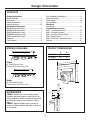
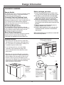
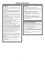
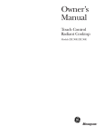
Installation
Instructions
If you have questions, call 800-GE-CARES or visit our website at: www.monogram.com
Downdraft Vent systems
36" Wide Models:
ZVB36
30" Wide Models:
ZVB30
Monogram.
®
We bring good things to life.
1
Safety Information
BEFORE YOU BEGIN
WARNING
Read these instructions completely
and carefully.
To reduce the risk of fire, electric
shock, or injury to persons, observe the
following.
A. Use this unit only in the manner intended by the
manufacturer. If you have questions, contact the
manufacturer.
B. Before service or cleaning unit, switch power off at
service panel and lock the service disconnecting
means to prevent power from being switched on
accidentally. When the service disconnecting
means cannot be locked, securely fasten a prominent warning device, such as a tag, to the service
panel.
IMPORTANT – Save these instructions for
local inspector’s use.
IMPORTANT
– Observe all governing
codes and ordinances.
Note to Installer – Be sure to leave these instructions with the Consumer.
Note to Consumer – Keep these instructions for
future reference.
Skill Level – Installation of these vents require basic
mechanical and electrical skills.
Completion Time – 1 to 3 hours.
• Proper installation is the responsibility of the installer.
Product failure due to improper installation is not
covered under the Warranty.
AVERTISSEMENT
Il faut observer les précautions suivantes
pour réduire les risques d’incendie, de choc électrique
ou de blessures.
If you received a damaged vent, you should
immediately contact your dealer or builder.
A. Utiliser cet appareil uniquement de la manière
prévue par le constructeur. Contacter le
constructeur pour toute question concernant cet
appareil.
For Monogram local service in your area,
1-800-444-1845.
For Monogram service in Canada,
1-888-880-3030.
For Monogram Parts and Accessories, call
1-800-626-2002.
B. Avant une intervention ou le nettoyage de l’appareil,
couper l’alimentation électrique au panneau
électrique et verrouiller le coupe-circuit pour
empêcher la remise accidentelle sous tension.
Quand il n’est pas possible de verrouiller le coupecircuit, mettre fermement en place un dispositif
d’avertissement, une pancarte par exemple, sur le
panneau électrique.
WARNING
This appliance must be properly
grounded.
• Do not attempt to repair or replace any part of the
downdraft system unless it is specifically recommended in this book. All other servicing should be
performed by a qualified technician.
AVERTISSEMENT
Cet appareil doit être
correctement mis à la terre.
• For general ventilating use only. Do not use the
exhaust hazardous or explosive materials and vapors.
• Installation work and electrical wiring must be done
by a qualified person(s). In accordance with all
applicable codes and standards including fire-rated
construction.
WARNING
TO REDUCE THE RISK OF FIRE,
USE ONLY METAL DUCTWORK.
To reduce the risk of fire and to properly exhaust air, be
sure to duct air outdoors. Do not vent exhaust air into
spaces within walls or ceilings or into attics, crawl
spaces or garages.
AVERTISSEMENT
UTILISER DES CONDUITS
MÉTALLIQUES POUR RÉDUIRE LES
RISQUES D’INCENDIE.
2
Design Information
CONTENTS
Design Information
Models Available ............................................................... 3
Accessories ....................................................................... 3
Product Dimensions .......................................................... 3
Advance Planning ......................................................... 4, 5
Installation Preparation
ZEU769 Combination Cutout ............................................ 6
ZEU30R Combination Cutout ............................................ 7
ZEU36R Combination Cutout ............................................ 7
ZGU36GG Combination Cutout ........................................ 8
ZGU375 Combination Cutout ............................................ 8
Clearances ......................................................................... 9
Parts Supplied .................................................................... 9
Tools and Materials Required ......................................... 9
Remove Packaging ........................................................... 9
Power Supply ................................................................... 10
Venting Options................................................................ 11
Ductwork
Duct Fittings ..................................................................... 12
Installation Instructions
Step 1, Install Downdraft Vent ...................................... 13
Step 2, Install the Ductwork .......................................... 13
Step 3, Install Raise/Lower Switch .............................. 14
Step 4, Connect Power ................................................... 15
Step 5, Install Filters, Check Operation ....................... 15
Cleaning ............................................................................ 15
PRODUCT DIMENSIONS
MODELS AVAILABLE
A
30”
36”
30” Models
36” Models
B
28-1/2”
34”
A
ZVB36
36” Wide Downdraft Vent
in white, black and stainless steel
B
27"
ZVB30
30” Wide Downdraft Vent
in white, black and stainless steel
2"
8-1/2"
Lift
ACCESSORIES
7-1/2" 2-1/4"
JXRB67 - Optional accessory for indoor remote
location of the blower/motor assembly. Use this kit
when the blower and motor assembly will be located
outside of the cabinet, such as below the cabinet
floor.
JXBC67 - Optional outdoor cover accessory for
remote installation of blower and motor assembly on
an outside wall.
3-1/8"
3-3/4"
6-1/4"
10-1/2"
3-3/8"
7-1/8"
3
Design Information
ADVANCE PLANNING
Remote Switch
Before you begin, you must:
The downdraft vent has a separate raise/lower switch.
Plan to install the switch in a convenient location
outside of the vent/cooktop cutout.
1. Review countertop dimension illustrations to be
sure you will have enough flat countertop surface.
2. Check to be sure that the total countertop depth
required (including minimum cutout to front edge
depth) allows enough space for a backsplash.
3. Review the cabinet illustration. Check to be sure
the interior cabinet depth will house the cooktop
burner box, the vent and the cutout clearance from
the front.
4. When countertop and cabinet depth present a
problem, review Creative Solutions.
5. Read this book completely to accurately plan the
installation location, clearances and ductwork
requirements.
Downdraft Vent and Cooktop Cutout
The installation of these downdraft vents with any
Monogram cooktop requires careful consideration. For
accurate planning, this book provides individual
dimension drawings for the vent and the Monogram
cooktop combined installation.
Countertop Requirements:
The countertop must have a deep flat surface to
accommodate the cooktop and the vent. Countertops
with a rolled front edge and backsplash may not
provide the flat surface area required.
Base Cabinet Requirements:
With careful planning you can achieve a custom look
with minimal adjustments.
The base cabinet must be deep enough to accommodate the minimum clearance to the front of the
countertop, the cooktop burner box and the vent.
Maintain Cutout Clearances
to Front Edge as Specified
Creative Solutions
• When the kitchen design calls for an against the
wall installation, move the base cabinet forward, 3”
to 5”. Filler panels or complimentary moldings can
be added to exposed cabinet sides.
• In an island or peninsula, use an extra deep
countertop. The countertop overhang at the
front can be adjusted to meet setback to cutout
requirements.
• When the cutout to front edge of the countertop
requirement is more than 2", add a bullnose trim to
the front edge of the countertop. Include the trim
thickness when measuring front edge to cutout
requirement. By adding the trim, the cooktop can be
moved forward, providing additional countertop
depth and interior cabinet space.
Filler Panel
Base
Cabinet
Filler Panel
Base Sink
1-7/8"
Trim
Countertop
Overhang
per Cooktop
Clearances
Must be
Maintained
Add a Bullnose Trim
or Other Decorative
Molding to Increase
Countertop Depth
and to Maintain
Required Clearance
From Front Edge to
Cutout.
End
Panel
Cover Panel
4
Downdraft
Vent
Design Information
Clearances
Ductwork
• The downdraft system with blower, motor and duct
work will occupy the cabinet below the countertop
and cooktop.
• The blower/motor assembly can be located below
the cabinet floor. The assembly will fit between 16”
floor joists. Order JXRB67 for indoor remote
locations.
• The blower motor assembly can also be installed
outdoors. Order JXBC67 for remote blower installations outdoors.
• Refer to “Cooktop Clearances” for information on
appropriate placement and necessary clearances
when planning installation.
• Refer to your specific cooktop installation instruction for other appropriate clearances.
• Avoid placing cabinetry directly above the cooking
surface when possible.
If cabinetry is used above the cooking surface:
• Use cabinets no more than 13” deep.
• Maintain 30” minimum clearance between cooktop
and unprotected cabinets directly above cooktop.
• If clearance is less than 30”, protect cabinet bottoms with flame-retardant millboard at least 1/4”
thick or gypsum board at least 3/16” thick covered
with 28 gauge sheet steel or .02” thick copper.
• Clearance between cooktop and protected
cabinetry must not be less than 24.”
Prepare ductwork to vent to the outdoors.
• Use the shortest and straightest duct run possible.
• The maximum permissible length for duct run is 150
feet.
• Refer to “Duct Fittings” chart to calculate equivalent
length for various duct configurations.
• The downdraft blower system is designed to use
3-1/4” x 10” ductwork. It can be transitioned to
6” round.
• Ductwork MUST be vented to the outside–never into
a crawl space, attic or other enclosed space.
• Determine the need for a wall cap or roof cap. Order
the cap in advance.
Electrical and Gas Locations
Plan the placement of the electrical outlet and gas
(if used) carefully. Gas or electrical outlets cannot be
placed on the back wall of the cabinet because it may
interfere with the downdraft plenum.
• Install a standard electrical outlet within reach of the
vents’ two foot long power cord.
• The vent and a Monogram gas cooktop combination
can operate from the same 120 volt standard duplex
outlet.
• Electric cooktops must operate from a separate
240 volt junction box.
EXCEPTION: Installation of a listed microwave oven
or cooking appliance over the cooktop shall conform
to the installation instructions packed with that
appliance.
• Working areas adjacent to the cooktop should 18”
minimum clearance between countertop and
cabinet bottom.
• Installation must conform with local codes.
5
Installation Preparation
CUTOUTS AND CLEARANCES
• Identify the cutout illustration for the cooktop model
you are installing.
• Draw lines on the countertop to follow as a cutting
guide. Measure and mark cooktop and vent overlaps
to be sure there is enough flat countertop depth.
• Measure carefully when cutting the countertop.
Make sure sides of the opening are parallel and rear
and front cuts are exactly perpendicular to sides.
• Measure to be sure there is room for clearances to
the front edge of the countertop.
• Refer to cooktop installation instructions to be sure
that models fit into the base cabinets being used.
ZEU769 ELECTRIC COOKTOPS WITH 36" VENT
1-3/4" Min. Cooktop Cutout to Rear
Vertical Combustible Surface
36"
1/4" Overlap
1/8" Gap
21-3/4"
Cutout
Depth
22-1/2"
Total Flat
Surface
Required
34" Cooktop and Vent Cutout
5/8" Cooktop Overlap
1-7/8"
ZEU769
19-7/8"
3/4"
3/4"
Thick
Support
Rail
Vent
22-3/4" Inside
22" to Support Rail
2-1/2" Min. Clearance to Cutout
Front Edge
of Countertop
2-1/2" to
Cutout
24-3/4"
2" Min. Cutout
to Side Walls
Countertop Cutout: Requires 22-1/2" flat countertop surface
and 24-3/8" total countertop depth.
6
Cabinet: Requires 22-1/2" inside
cabinet depth. Remove rear
support rail.
Installation Preparation
ZEU30R DIGITAL COOKTOPS WITH 30" VENT
2-1/2" to
Cutout
1-3/4" Min. Cooktop Cutout to Rear
Vertical Combustible Surface
29-7/8" (SS)
1/4" Overlap
29-3/4" (B,W)
3/4"
1-7/8"
ZEU30
20-3/8"
3/4"
Thick
Support
Rail
1/8" Gap
22-1/4"
Cutout
Depth
23-1/2" (SS)
23-3/8" (B,W)
Total Flat
Surface
Required
at Center
28-1/2"
Cooktop Area Cutout
5/8" Cooktop Overlap
(1-1/8" at Center)
Front Edge
of Countertop
2-1/2" Min.
Clearance to Cutout
Vent
22-3/4" Inside
22" to Support Rail
24-3/4"
2" Min. Cutout
to Side Walls
Countertop Cutout: Requires 23-3/8" (B,W) 23-1/2" (SS) flat
countertop surface. Requires 24-3/4" (B,W) and 24-7/8" (SS) total
countertop depth.
Cabinet: Requires 23" inside cabinet
depth. See Creative Solutions, install in
an island or move cabinet base forward.
ZEU36R DIGITAL COOKTOPS WITH 36" VENT
1-3/4" Min. Cooktop Cutout to Rear
Vertical Combustible Surface
1-7/8"
ZEU36
19-7/8"
36-1/8" (SS)
36" (B,W)
1/4" Overlap
2-3/4"
21-3/4"
Cutout
34"
Depth 19-1/8"
Cooktop and Vent Cutout
Cooktop
Cutout 5/8" Cooktop Overlap
Depth (1-1/8" at Center)
2-1/2" to
Cutout
3/4"
3/4"
Thick
Support
Rail
1/8" Gap
23" (SS)
22-7/8" (B,W)
Total Flat
Surface
Required
Vent
22-3/4" Inside
22" to Support Rail
24-3/4"
Front Edge
of Countertop
2-1/2" Min.
Clearance to Cutout
2" Min. Cutout
to Side Walls
Cabinet: Requires 22-1/2" inside cabinet depth.
Remove rear support rail.
Countertop Cutout: Requires 22-7/8" (B,W) 23"
(SS) flat countertop surface. Requires 24-1/4" (B,W)
and 24-3/8" (SS) total countertop depth.
7
Installation Preparation
ZGU36GG GAS COOKTOPS WITH 36" VENT
2-1/4" Min. Cooktop Cutout to Rear
Vertical Combustible Surface
36"
1-7/8"
ZGU36
20-1/16"
1/4" Overlap
1/8" Gap
21-3/4"
Cutout
Depth
2-1/2" to
Cutout
3/4"
23-1/2" (SS)
23-3/8" (B,W)
Total Flat
Surface
Required
at Center
34" Cooktop and Vent Cutout
13/16" Cooktop Overlap
(1-1/2" at Center)
3/4"
Thick
Support
Rail
Vent
22-3/4" Inside
22" to Support Rail
2-1/2" Min.
Clearance to Cutout
Front Edge
of Countertop
24-3/4"
6" Min. Cutout
to Side Walls
Countertop Cutout: Requires 23-3/8" (B,W) 23-1/2" (SS) flat
countertop surface. Requires 24-3/8" (B,W) and 24-1/2" (SS) total
countertop depth.
Cabinet: Requires 22-11/16" inside
cabinet depth. Remove rear support rail.
ZGU375 GAS COOKTOPS WITH 36" VENT
3-3/8" Min. Cooktop Cutout to Rear
Vertical Combustible Surface
36-1/2"
34" Vent Cutout
1/4" Overlap
1-7/8"
ZGU375
19-7/16"
9/16"
9/16"
2-9/16"
21-7/16"
Cutout
Depth 18-7/8"
Cooktop
Cutout
2-3/4" to
Cutout
1"
1/8" Gap
35-5/16"Cooktop
Cutout
7/16" Cooktop Overlap
(1-1/4" At Center)
Front Edge
of Countertop
22-3/4"
Total Flat
Surface
Required
3/4"
Thick
Support
Rail
Vent
22-3/4" Inside
22" to Support Rail
2-3/4" Min.
Clearance to Cutout 11-9/16" Min. Cutout
to Side Walls
Countertop Cutout: Requires 22-3/4" flat countertop surface and
24-1/4" total countertop depth.
8
24-3/4"
Cabinet: Requires 22-5/16" inside
cabinet depth. Remove rear
support rail.
Installation Preparation
CLEARANCES
CAUTION
Wall coverings, countertops and cabinets should
withstand 200° heat generated by any cooktop.
Gas - 6" to 11-9/16"
Electric - 2"
Clearance to Side Walls
PRUDENCE
Les revêtements muraux, les dessus de comptoir et
les armoires de cuisine doivent résister à la
température de 95 ºC (200 ºF) créée par toute table
de cuisson.
13"
Max.
13"
Max.
30"
Min. 18"
Min.
30"
Min. 18"
Min.
2" Min. to
Wall When
Installed
2" Min. to
Wall When
Installed
8" Min. to
Wall When
Installed
8" Min. to
Wall When
Installed
Electric Cooktop Clearances When Installed
Gas Cooktop Clearances When Installed
PARTS SUPPLIED
TOOLS AND MATERIALS REQUIRED
Open the carton and remove parts package.
Check contents to be sure all pieces are present.
1 Wire and
white
connector
• Large flat-blade screwdriver.
• Jig saw
• Carpenter’s square
• Ductwork to suit the installation
4 Stabilizing Brackets
REMOVE PACKAGING
• Remove the shipping materials and the carton, set
carton aside. The carton can be used as a pad when
changing or adjusting vent direction.
2 Plastic Strain Reliefs
1 Switch
Cover Plate
2 Wire boxes
and screws
1 Attachment
Bracket
9
Installation Preparation
Do Not Locate Gas or Electrical
Connections Within Shaded Area
POWER SUPPLY
WARNING
FOR PERSONAL SAFETY:
29-1/2"
Remove house fuse or open
circuit breaker before beginning
installation.
Electrical
Outlet
12" Above
Cabinet Floor
Do not use an extension cord or
adapter plug with this appliance. Follow National
electrical codes or prevailing local codes and ordinances.
34" for 36" Models
28-1/2" for 30" Models
AVERTISSEMENT
SÉCURITÉ
IMPORTANT
Enlever le fusible ou déclencher le
disjoncteur du panneau de la
maison avant de commencer
l’installation.
(Please read carefully).
The power cord of this appliance is equipped with a
three-prong (grounding) plug which mates with a
standard three-prong grounding wall receptacle to
minimize the possibility of electric shock. The
customer should have the wall receptacle and
circuit checked by a qualified electrician to make
sure the receptacle is properly grounded and has
correct polarity.
• Where a standard two-prong wall receptacle is
encountered, it is the personal responsibility and
obligation of the customer to have it replaced with
a properly grounded three-prong wall receptacle.
Do not, under any circumstances, cut or
remove the third (ground) prong from the
power cord.
DO NOT USE AN EXTENSION CORD.
Ne pas utiliser de rallonge ni d’adaptateur de prise de
courant avec cet appareil. Il faut respecter les codes
nationaux de l’électricité et les réglementations ou
codes locaux.
This downdraft vent must be supplied with 120V, 60Hz.,
and connected to an individual, properly grounded
branch circuit, protected by a 15 or 20 ampere circuit
breaker or time delay fuse.
Gas Cooktops
If this vent is installed in combination with a
Monogram gas cooktop, it may operate from the same
duplex outlet.
Electric Cooktops
If this vent is installed in combination with a
Monogram electric cooktop, the vent must operate
from a separate 120V outlet.
• A properly grounded 3-prong receptacle should be
located within reach of the vents’ two foot power
cord.
• Locate the receptacle inside the cabinet on the right
side wall. The receptacle cannot be placed on the
back of the cabinet wall where it may interfere with
the downdraft plenum. See illustration.
10
Installation Preparation
Loosen Screws
to Adjust
3-1/2" to
Left or Right
VENTING OPTIONS
• The downdraft vent is shipped with the
discharge outlet pointing straight down and
can be changed to the left or right side.
• The blower outlet is sized for 3-1/4” x 10”
and can be transitioned to 6” round.
Side to side adjustments:
The entire blower mounting plate can be
adjusted 3-1/2” to the left or right. This will
help to align vent discharge to house
ductwork.
Discharge Down
(As Supplied)
Discharge Left
Discharge direction
Discharge Right
To locate the ductwork holes in the
cabinet floor or side walls:
The blower assembly may be removed and turned
90° for a left or right side discharge.
• A left or right 90° direction adjustment should be
performed before dropping into the countertop
opening.
• Flatten the shipping box to use as a pad.
• Lay the vent on its back and onto the pad.
• Temporarily, place vent into the countertop opening.
• Push the vent all the way to the back of the opening.
• If you are transitioning to 6” round (obtained
locally), place transition piece over the discharge
outlet.
• Mark the location and remove the assembly.
• Cut holes and install ductwork connections.
• Order JXRB67 for installation of the blower and
motor below the floor.
• Order JXBC67 for installation of the blower and
motor outdoors.
To change to a left or right discharge:
• Remove the 4 screws holding the blower to the
mounting plate assembly. Retain screws.
• Remove blower assembly, turn it over to access the
4 nuts holding the blower to the mounting plate.
Remove the nuts.
IMPORTANT: Do not lift motor by power cable.
• Turn the blower to left or right discharge direction
and reinstall the 4 nuts.
• Reinstall blower and mounting plate with original
screws.
11
Ductwork
Duct
Fittings
Use this form to
compute maximum
permissible lengths
for duct runs to
outdoors.
Duct Piece
Note: Do not exceed
maximum permissible
equivalent lengths!
Flexible ducting:
If flexible metal
ducting is used, all the
equivalent feet values
in the table should be
doubled. The flexible
metal duct should be
straight and smooth
and extended as
much as possible.
Do NOT use flexible
plastic ducting.
Downdraft Vent
150' maximum
equivalent length
Note: Any home
ventilation system,
such as a cooktop with
a downdraft exhaust
mechanism, may
interrupt the proper
flow of combustion air
and exhaust required
by fireplaces, gas
furnaces, gas water
heaters and other
naturally vented
systems. To minimize
the chance of interruption of such
naturally vented
systems, follow the
heating equipment
manufacturer’s
guidelines and safety
standards such as
those published by
NFPA and ASHRAE.
Dimensions
Equivalent
Length*
6" round,
straight
1 ft.
(per foot
length)
3-1⁄4" x 10"
straight
1 ft.
(per foot
length)
6"
90° elbow
15 ft.
6"
45° elbow
9 ft.
3-1⁄4" x 10"
90° elbow
16 ft.
3-1⁄4" x 10"
45° elbow
5 ft.
3-1⁄4" x 10"
90° flat elbow
18 ft.
6" round
to 3-1⁄4" x 10"
transition
7 ft.
3-1⁄4" x 10"
round to 6"
transition
5 ft.
6" round to
31⁄4" x 10"
transition
90° elbow
20 ft.
3-1⁄4" x 10" to 6"
round transition
90° elbow
12 ft.
6" round
wall cap
with damper
21 ft.
3-1⁄4" x 10"
wall cap
with damper
27 ft.
6" round
roof cap
20 ft.
6" round
roof vent
24 ft.
* Actual length of straight duct plus duct fitting
equivalent. Equivalent length of duct pieces are based
on actual tests conducted by GE Evaluation Engineering and reflect requirements for good venting
performance with any downdraft cooktop.
12
Quantity
Used
Total
Equivalent
Length
Total Duct Run
Installation Instructions
STEP 1 INSTALL DOWNDRAFT
VENT
STEP 2 INSTALL THE DUCTWORK
• The downdraft blower system is designed for use
with 3-1/4" x 10" ductwork. It can be transitioned to 6"
round.
• Ductwork MUST be vented to the outside – never in a
crawl space, attic or other enclosed space.
• 6" PVC duct should be used when installing under a
concrete slab.
Place the downdraft vent into the countertop cutout,
against the back side.
Note: Local building code must be followed for
installation in specifying approved type and schedule
of PVC duct used.
Secure Upper
Brackets With
Screws Located
on the Side of
Case and Attach
to Back Wall
of Cabinet
Duct Tape
Over Seam and Screw
Air
Flow
Screw
• DO NOT USE flexible plastic ducting.
• Always use appropriate roof or wall cap with
damper. Laundry type wall caps should never be
used.
• Use the straightest duct run possible.
• For satisfactory performance the duct run should not
exceed 150 ft. or its equivalent length when bends or
various fittings are used. Refer to the table of equivalent lengths to calculate your installation.
• Install ductwork so the piece of duct nearest the
downdraft unit slots INTO the next piece of the duct.
Secure the joints with self-tapping screws and apply
duct tape around the joints to ensure an airtight seal.
Secure the Lower Brackets
to Blower Housing
• Secure the downdraft to the countertop supplied
brackets. See illustration.
• Fasten two brackets to vent sides and secure to
cabinet back wall.
• Install two brackets on the bottom of the vent.
Attach brackets to slide screws on the vent and to
the floor using wood screws (not supplied).
• When installing in a tile countertop surface, it may
be necessary to apply a locally approved caulking
to cover any gaps.
13
Installation Instructions
STEP 3 INSTALL RAISE/LOWER SWITCH
WARNING:
AVERTISSEMENT
Disconnect electrical power from unit before
beginning switch installation. Failure to do so could
result in personal injury or damage to the electrical
controls.
Il faut débrancher l’alimentation électrique de
l’appareil avant de commencer l’installation de
l’interrupteur. Il faut suivre cette directive pour éviter
des blessures ou endommager les commandes
électriques.
Determine the location for the RAISE/LOWER switch.
The wiring lead is 68” long.
Raise/Lower
Switch
Trim
Connect Raise/Lower Wire Lead to Wire Box
• Thread wire end with the connector through the
hole on the end of a wire box. Pull approximately
3" additional wire length beyond the open end of
the box.
• Connect the mating wire connectors.
• Install the wire box onto the bottom of the
countertop or directly behind the switch. Use
adhesive or screws appropriate for the type of
countertop.
• Place plastic strain relief over the wire, just outside
of the hole at the end of the wire box. Do not pinch
or twist the wire. Snap the strain relief closed and
press into the hole.
Mounting
Bracket
3/8" Hole
Pull 3"
Length
Out of
Box
2 Pin
Connector
Control
Box
Strain Relief
• Drill a 3/8” hole into the desired location. Use the
mounting bracket as a template to locate the hole
accurately. Check for interference between the
switch cover, adjacent objects and cooktop/vent
overlaps.
• If switch is mounted into a tile surface, drill the hole
between tiles. Use locally approved caulking to cover
any gaps.
• Center the mounting bracket over the hole and mark
pilot holes. Remove and drill holes according to type
of countertop.
• Mount the metal switch bracket with screws (not
provided). Choose screws for your type of countertop
or use locally approved adhesive.
• Remove protective film from the top of the switch trim.
• Peel film from the adhesive strips on the back of the
switch trim. Thread the wire lead through the mounting bracket and countertop. Press trim over the
mounting bracket to set the adhesive.
Connect Wire Lead to Control Box
• Thread the long 68" wire lead through the end of the
other wire box.
• Push wire leads into the white connector provided.
• Push wire connector into the mating connector on
the control box. Install the wire box onto the end of
the control box with screws provided.
• Place plastic strain relief over the wire, just outside
of the hole at the end in the wire box. Do not pinch or
twist the wire. Snap the strain relief closed and
press into the hole.
• Coil the excess wire and position away from moving
parts and cabinet contents.
14
Installation Instructions
CLEANING
STEP 4 CONNECT POWER
Cleaning a Stainless Steel Downdraft Vent
Stainless steel has some unique cleaning
characteristics. In order to keep your vent looking like
new, we suggest cleaning it with Stainless Steel Magic
or similar product.
Plug power cord into properly grounded receptacle.
STEP 5 INSTALL FILTERS,
CHECK OPERATION
Stainless Steel Magic is available at Ace, True Value,
Servistar, HWI and other leading stores. It is also
available through GE Parts by calling 1-800-626-2002.
Order part number WX10X15.
To raise the vent, press the RAISE/LOWER switch.
The switch is installed in a separate location.
• Tip filter into the opening and pull slide straight
down so that the filter rests on the inside filter
supports.
• Install the opposite filter.
• To turn the fan on, slide control to HIGH. Select
desired speed by sliding control between HI and
LO settings.
Note: It is not necessary to turn the fan OFF before
lowering the vent. The fan will automatically turn off
when the vent is lowered. When the fan is not turned
off before lowering the vent, it will automatically
come on at the previously set speed when the vent is
fully raised.
To lower the vent, press the RAISE/LOWER switch
and hold until the vent begins to lower.
15
Note: While performing installations described in this book,
safety glasses or goggles should be worn.
For Monogram® local service in your area, call
1-800-444-1845.
Note: Product improvement is a continuing endeavor at
General Electric. Therefore, materials, appearance and
specifications are subject to change without notice.
Monogram.
®
We bring good things to life.
GE Consumer Products
General Electric Company
Louisville, KY 40225
© 2003 General Electric Company
Pub. No. 49-80185
Dwg. No. 164D4290P341
(N.D. 682) 2/03
959-0344-001
16