1
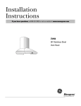
Installation
Instructions
If you have questions, call 800-GE-CARES or visit our website at: www.monogram.com
30", 36" and 48"
Proessional Vent Hoods
48" Wide Models:
ZV881, ZV891, ZV880, ZV890
36" Wide Models:
ZV671, ZV681, ZV670, ZV680
30" Wide Models:
ZV370, ZV371
Monogram.
®
We bring good things to life.
Installation Preparation
BEFORE YOU BEGIN
WARNING:
Read these instructions completely and carefully.
•
TO REDUCE THE RISK OF FIRE, ELECTRICAL
SHOCK OR INJURY TO PERSONS, OBSERVE
THE FOLLOWING:
A. Use this unit only in the manner intended by the
manufacturer. If you have any questions, contact the
manufacturer.
B. Before servicing or cleaning unit, switch power off
at the service panel and lock service panel to prevent
power from being switched on accidentally. If the
service panel cannot be locked, fasten a tag or
prominent warning label to the panel.
IMPORTANT - Save these instructions for
local inspector’s use.
•
IMPORTANT - Observe all governing
codes and ordinances.
• Note to Installer - Be sure to leave these instructions with the Consumer.
• Note to Consumer - Keep these instructions with
your Owner’s Manual for future reference.
• Skill Level – Installation of this appliance requires
basic mechanical and electrical skills.
• Completion time – 1 to 3 hours.
• Proper installation is the responsibility of the
installer.
• Product failure due to improper installation is not
covered under the Warranty.
For general ventilating use only. Do not use to
exhaust hazardous or explosive materials or vapors.
Structural framing, installation work and electrical
wiring must be done by qualified person(s).
In accordance with all applicable codes and standards
including fire-rated construction.
For Monogram local service in your area,
1-800-444-1845.
For Monogram service in Canada, call
1-888-880-3030.
For Monogram Parts and Accessories, call
1-800-626-2002.
Sufficient air is needed for proper combustion and
exhausting of gases through the flue (chimney) of
fuel burning equipment to prevent back drafting.
Follow the heating equipment manufacturer’s
guideline and safety standards such as those published by the National Fire Protection Association
(NFPA), and the American Society for Heating,
Refrigeration and Air Conditioning Engineers
(ASHRAE), and the local code authorities.
CAUTION:
Due to the weight and size of these vent hoods and to
reduce the risk of personal injury or damage to the
product, TWO PEOPLE ARE REQUIRED FOR
PROPER INSTALLATION.
READ CAREFULLY.
KEEP THESE INSTRUCTIONS.
Local codes vary. Installation electrical connections
and grounding must comply with applicable codes.
In the absence of local codes, the vent should be
installed in accordance with National Electrical Code
ANSI/NFPA 70-1990 or latest edition.
WARNING:
To reduce the risk of fire or electrical shock, do not
use this range hood with any external solid-state speed
control device. Any such alteration from original
factory wiring could result in damage to the unit and/
or create an electrical safety hazard.
TO REDUCE THE RISK OF FIRE, USE ONLY
METAL DUCTWORK.
CONTENTS
Installation Preparation
Models, Duct Covers, Ductwork Accessories ................... 3
Product Dimensions, Product Clearances ...................... 4
Advance Planning ............................................................. 5
Power Supply ................................................................... 5
Duct Fittings ...................................................................... 6
Installation Instructions
Tools and Materials Required .......................................... 7
Step 1, Remove Packaging ............................................... 7
Step 2, Check Installation Hardware ............................... 7
Step 3, Determine Accessories, Ductwork and Wiring
Locations .............................................................. 8
Step 4, Recommended Wall Mounting Method
Wall Framing For Hood Support ........................ 9
Step 5, Install Hood Onto Wall ...................................... 10
Step 6, Alternate Soffit Mounting Method
Soffit Framing .................................................. 11
Step 7, Connect Electrical .............................................. 12
Step 8, Connect Ductwork ............................................. 12
Step 9, Reassemble Hood ............................................... 12
Step 10, Install Duct Cover ............................................ 13
Step 11, Install Filters ..................................................... 13
2
Installation Preparation
MODELS AVAILABLE
48" Wide Models:
ZV881, ZV880 – with tapered sides
ZV891, ZV890 – with straight sides
These vent hoods are designed to be installed onto a
wall. They can be installed beneath a soffit and with duct
cover accessories that conceal ductwork.
36" Wide Models:
ZV671, ZV670 – with tapered sides
ZV681, ZV680 – with straight sides
Choose 48" and 36" wide models with straight sides, or
models with sides that taper inwards from the bottom to
the top. 30" models have straight sides.
30" Wide Models:
ZV371, ZV370 – with straight sides
DUCT COVER ACCESSORIES
Before you begin:
Decorative duct covers are available in 6" or 12" heights.
The duct covers conceal the ductwork running from the
top of the hood to the ceiling or soffit. Before you begin,
you should determine the installation height of the hood
and order the correct size duct cover.
• Order the duct cover accessory at the same time as the
vent hood and have on site before installation. Be sure to
order the duct cover corresponding to your model.
Optional 6" or 12"
Duct Cover
Optional 6" or 12"
Duct Cover
Square Shape Duct Covers for Straight Sided Models
Oval Shape Duct Covers for Models for Tapered Sided Models
Hood Model
ZV881 , ZV880
ZV671, ZV670
6” Duct Cover
ZX6DC48
ZX6DC36
Dimensions
6”Hx27-3/8”Wx10-1/4”D
6”Hx22-1/2”Wx9-3/16”D
Hood Model
ZV881, ZV880
ZV671, ZV670
12” Duct Cover
ZX12DC48
ZX12DC36
Dimensions
12”Hx27-3/8”Wx10-1/4”D
12”Hx22-1/2”Wx9-3/16”D
DUCTWORK ACCESSORIES
(for 48" wide models only)
Transition duct pieces are available for 48" wide
models. These pieces fit over the outlet on top
of the hood and will fit into a soffit or can be
concealed with a 12" duct cover.
Hood Model
ZV891, ZV890
ZV681, ZV680
ZV371, ZV370
6” Duct Cover
ZX6DC49
ZX6DC38
ZX6DC30
Dimensions
6”Hx47-7/8”Wx12”D
6”Hx35-7/8”Wx12”D
6”Hx29-7/8”Wx12”D
Hood Model
ZV881, ZV880
ZV681, ZV680
ZV371, ZV370
12” Duct Cover
ZX12DC49
ZX12DC38
ZX12DC30
Dimensions
12”Hx47-7/8”Wx12”D
12”Hx35-7/8”Wx12”D
12”Hx29-7/8”Wx12”D
10"
8-3/4"
CL
6-5/8" 12"
to CL
8-1/4"
18-1/2"
4-1/2"
ZX48AY, transition to
10" round for vertical exhaust
3
4-1/2"
18-1/2"
ZX48BY, transition to
10" round for horizontal exhaust
Installation Preparation
12"
PRODUCT DIMENSIONS
35"
18"
12"
47-7/8"
25"
47-7/8"
ZV881, ZV880
18"
12"
25"
23"
47-7/8"
18"
ZV891, ZV890
35-7/8"
25"
12"
35-7/8"
ZV671, ZV670
12"
29-7/8"
18"
18"
35-7/8"
25"
25"
ZV681, ZV680
29-7/8"
ZV371, ZV370
PRODUCT CLEARANCES
These vent hoods must be installed 25" min. to 36” max.
above the cooking surface. Installation will be easier if
the vent hood is installed before the range or cooktop.
The rating plate is located behind the filter cutouts.
Remove filters to verify your model number.
Soffit Installation
Soffit
25" Min.
36" Max.
Ceiling
Wall Mount Installation
Note: Clearances may vary
due to type of cooking
product and local codes.
Check with local inspectors
to be sure standard is
applicable.
4
25" Min.
36" Max.
Installation Preparation
ADVANCE PLANNING
Ductwork Planning
• Determine the exact location of the vent hood.
• Plan the route for venting exhaust to the outdoors.
• Use the shortest and straightest duct route possible.
For satisfactory performance, duct run should not
exceed 100 feet equivalent length for any duct
configurations.
• Refer to “Duct Fittings” chart to compute the maximum permissible length for duct runs to the outdoors.
See page 6.
• Use metal ductwork.
– For 48" models use: 3-1/4" x 24" or 10" round.
– For 36" and 30" models: 7" to 10" round or
3-1/4" x 12" to 3-1/4" x 24".
• Install a wall or roof cap with damper at the exterior
opening.
48" Wide Model Duct Transitions
• Transition duct pieces are available for 48" wide
models. See illustrations, ZX48BY and ZX48AY transition pieces, page 3.
Installation Framing for Adequate Support
These vent hoods are heavy. Adequate structural
support must be provided. Hoods must be secured to
vertical studs in the wall.
• Additional studs may be required.
• We strongly recommend that the vent hood and duct
cover be on site before final framing and wall finishing.
This will also help to accurately locate the ductwork
and electrical service.
Decorative Duct Covers
Decorative duct covers are available for all models. The
duct covers conceal the ductwork running from the top
of the hood to an 8 ft. ceiling or soffit. Duct covers are
available in 6" or 12" heights. See page 8 to determine
need and size. See page 3 to order exact part number.
• To avoid unsightly gaps above the hood, plan the
installation height carefully.
Determine the size of the wall or roof cap for your
model and installation.
• Order the caps and any transitions needed in advance.
See “Duct and Duct Fittings” listed in your local yellow
pages. Be sure to include equivalent lengths of caps
and transitions when calculating the total duct run.
See “Duct Fittings”, page 6.
POWER SUPPLY
• Connect the wiring to the house wiring in accordance
with local codes.
IMPORTANT - (Please read carefully)
House wiring location
WARNING:
• The junction box is located inside the top of the hood.
• Electrical connections can be made at the top of the
hood or from the inside.
• Route house wiring through the ceiling, soffit or back
wall as close to the installation location as possible.
FOR PERSONAL SAFETY, THIS APPLIANCE MUST BE
PROPERLY GROUNDED.
Remove house fuse or open circuit breaker before
beginning installation.
Grounding instructions
Do not use an extension cord or adapter plug with this
appliance. Follow National electrical codes or prevailing
local codes and ordinances.
The grounding conductor must be connected to a
ground metal, permanent wiring system, or an
equipment-grounding terminal or lead on the hood.
Electrical supply
WARNING: The improper connection of
This vent hood must be supplied with 120V, 60Hz, and
connected to an individual, properly grounded branch
circuit, and protected by a 15 or 20 amp circuit breaker
or time delay fuse.
• Wiring must be 2 wire with ground.
• If the electrical supply does not meet the above
requirements, call a licensed electrician before
proceeding.
the equipment-grounding conductor can result in a risk
of electric shock. Check with a qualified electrician or
service representative if you are in doubt whether the
appliance is properly grounded.
5
Installation Preparation
DUCT FITTINGS
Duct Piece
Use this chart to compute maximum
permissable lengths for duct runs to
outdoors.
Note: Do not exceed maximum permissable equivalent
lengths!
Maximum duct length:
100 foot for vent hoods.
Flexible ducting:
If flexible metal ducting is used, all
the equivalent feet values in the table
should be doubled. The flexible metal
duct should be straight and smooth
and extended as much as possible.
Do NOT use flexible plastic ducting.
Note: Any home ventilation system, such as a
ventilation hood, may interrupt the proper flow of
combustion air and exhaust required by fireplaces,
gas furnaces, gas water heaters and other naturally
vented systems. To minimize the chance of interruption
of such naturally vented systems, follow the heating
equipment manufacturer’s guidelines and safety
standards such as those published by NFPA and ASHRAE.
48" Hoods Must Use
10" Round Duct
or 3-1/4" x 24"
Note: Outlet on top of 48" hood
is 4-1/2" x 18-1/2".
30" and 36" Hoods
May Use 7" to 10"
Round, or 3-1/4" x 12"
to 3-1/4" x 24"
Note: Outlet on top of 36" and
30" hoods is 7" round.
Dimensions
Equivalent
Length*
Round,
straight
1 ft.
(per foot
length)
3-1⁄4" x 12" or
3-1/4" x 24"
straight
1 ft.
(per foot
length)
90° elbow
15 ft.
45° elbow
9 ft.
3-1⁄4" x 12" or
3-1/4" x 24"
90° elbow
15 ft.
3-1⁄4" x 12" or
3-1/4" x 24"
45° elbow
9 ft.
3-1⁄4" x 12" or
3-1/4" x 24"
90° flat elbow
20 ft.
7" round to
3-1⁄4" x 12" or 10" round
to 3-1/4" x 24" transition
1 ft.
3-1⁄4" x 12" to 7" round
or 3-1/4" x 24" to 10"
round transition
5 ft.
7" round to
3-1/4" x 12" or 10" round
to 3-1/4" x 24"
transition 90° elbow
5 ft.
Quantity
Used
3-1⁄4" x 12" to 7" round
or 3-1/4" x 24" to 10"
round transition 90° elbow 15 ft.
Round
wall cap
with damper
30 ft.
3-1⁄4" x 12" or
3-1/4" x 24" wall cap
with damper
30 ft.
Round
roof cap
26 ft.
Round
roof vent
24 ft.
* Actual length of straight duct plus duct fitting equivalent.
Equivalent length of duct pieces are based on actual
tests conducted by GE Evaluation Engineering and
reflect requirements for good venting performance
with any ventilation hood.
6
Total Duct Run
Total
Equivalent
Length
Installation Instructions
TOOLS AND MATERIALS REQUIRED (NOT SUPPLIED)
• Tape measure
• Spirit level
• Wire cutter
• Wire stripper
• Wire nuts
• Electric drill and 3/16" bit, 1/2" and 7/16" socket
• Torx screwdriver
• Hammer
• Safety glasses
• Gloves to protect against sharp edges
• 120V 60Hz. 15 or 20 Amp, 2 wire with ground. Properly grounded
branch circuit.
• Strain relief
• Metal ductwork, length to suit installation.
– 3-1/4" x 24" or 10" round for 48" models.
– 7" to 10" round or 3-1/4" x 12" to 3-1/4" x 24" for 30" and 36" models.
Optional Materials for Mounting:
– 47-1/2" x 18" plywood for 48" models
– 35-1/2" x 18" plywood for 36" models
– 29-1/2" x 18" plywood for 30" models
(for tapered hoods, trim to fit)
1 REMOVE PACKAGING
AND DISASSEMBLE
2 CHECK INSTALLATION
HARDWARE
• Remove accessory box from hood crate.
• Separate wood crate from pallet. Lift to remove crate.
The hood is laying on its back, bolted to the pallet.
• Remove tape, packaging, heat lamp(s) and halogen
bulbs (if installed).
• Locate the hardware accessory box packed with vent
hood and check contents.
Halogen Bulbs
(may be shipped
installed)
Grease
Tray(s)
Rear Liner
Filter(s)
Heat Lamps
(may be shipped installed)
• Remove 10 screws along the inside top, bottom and
both sides. (Fewer screws on some models.)
• Lift out rear liner.
• Remove hold-down bolts.
• Remove and discard pallet.
2 Tinnerman Clips with screws
(extra, use if needed)
30" and 36" Models
30" and 36" Models
48" Models
6-1/2"
6-1/2"
3-1/2"
3-1/2"
48" Models
8-7/8"
14-7/8" For 48" Models
14-7/8"
6-1/2"
6-1/2"
8-7/8" For 30" and 36" Models
Drill 3/16" Pilot Holes
Drill 3/16" Pilot Holes
1-1/2"
1-1/2"
Align Edge 24-1/4" to 30-1/4" From Ceiling
or 66" to 72" From Floor
✄
✄
✄
Cut Along Line
Installation Template
Six, 5/16" lag screws,
2" long with washers
Remove Hold-Down Bolts
7
✄
Cut Along Line
Installation Instructions
3 DETERMINE DUCT COVER ACCESSORIES,
DUCTWORK AND WIRING LOCATIONS
We recommend that the vent hood and decorative duct
cover (if used) be on site before final framing and wall
finishing. This will help to accurately locate studs,
ductwork and electrical service. Read these instructions
to determine the need for duct cover accessories, duct
fittings and wiring locations.
Centerline To Wall
FOR CEILING
VENT DUCTING
House
Wiring
Duct Hole
Duct Cover Accessories:
Perform this step to determine the need and size of an
accessory duct cover. These measurements assume a
typical 8ft. ceiling height.
• Measure down from the ceiling 24-1/4". Measure again
to 30-1/4". Use a level to draw a horizontal line at both
locations.
– 24-1/4" is the total of a 6" duct cover, 18" hood height,
plus 1/4" for clearance.
– 30-1/4" is the total of a 12" duct cover, 18" hood
height, plus 1/4" for clearance.
FOR WALL VENT DUCT
30" and 36" Models
30" and 36" Models
48" Models
6-1/2"
8-7/8"
14-7/8" For 48" Models
14-7/8"
6-1/2"
8-7/8" For 30" and 36" Models
6-1/2"
• Check the distance from the floor to the horizontal
lines. The horizontal lines must fall between 66" and
72" from the floor.
• Determine the exact installation location. Use the level
to draw the centerline up to the ceiling.
• Choose the location height and tape template onto the
wall. Be sure the template is straight and level.
For Ceiling Heights greater than 8 ft.
Add 36" floor to cooktop height, distance from cooking
surface to bottom of hood (36" max.) and hood height
(18") to determine use of duct covers.
24-1/4"
or
30-1/4"
6-1/2"
3-1/2"
3-1/2"
48" Models
Centerline 7" or 12"
Min. Above
Top of Hood
Drill 3/16" Pilot Holes
Drill 3/16" Pilot Holes
1-1/2"
1-1/2"
Align Edge 24-1/4" to 30-1/4" From Ceiling
or 66" to 72" From Floor
✄
✄
Cut Along Line
✄
✄
Cut Along Line
WALL DUCTING:
If ductwork will vent to the rear:
• Use the level to draw a line straight up from the
centerline on the template.
30" and 36" models:
• Measure 7" above the top of the hood shown on the
template to the centerline of a 7-1/2" dia. duct hole.
(Hole may need to be elongated for duct elbow.)
48" wide models:
• Measure at least 6-5/8" above the top of the hood
shown on the template to the centerline of a 10-1/2"
dia. hole duct.
Installation below a soffit:
Ductwork can be concealed behind the soffit. Duct
covers will not needed.
Determine Ductwork Locations:
CEILING DUCTING:
If ductwork will vent straight up to the ceiling:
• Use the level to draw the centerline straight up to the
ceiling.
30" and 36" models:
• For 7" round, measure, 4-3/8" from the back wall to the
centerline of a 7-1/2" hole on the ceiling.
48" wide models:
• For 10" round duct (using ZX48AY duct transition),
measure 6-5/8" from the back wall to the centerline of
a 10-1/2" hole.
House Wiring Location:
• The junction box is located on the top right side of all
hood models.
• Route house wiring as close to the installation location
as possible; through the ceiling, soffit or back wall.
Remove the template:
• Remove the template and set aside before going to step
4. In the next step you must locate studs or provide
additional support for mounting the hood.
IMPORTANT: Any transition used must be measured
and calculated to determine exact centerline.
8
Installation Instructions
4 Recommended Mounting Method
PROVIDE WALL FRAMING FOR HOOD SUPPORT
• Mark the exact location of the vent hood as determined in step 3.
• Provide mounting support as shown below using
METHOD 1 or METHOD 2.
IMPORTANT: Framing must be
capable of supporting 130 lbs.
METHOD 2
7" Min. (30" and 36" Models)
10" Min. (48" Models)
Opening for Ductwork
METHOD 1
7" Min. (30" and 36" Models)
10" Min. (48" Models)
Opening for Ductwork
Hood
Width
Additional
Wall Studs
Installed
To Match
Mounting
Holes
Hood
Width
Centerline of
Installation
Space
No Additional
Wall Studs needed
Plywood Sheet
(Wall Hole Cutout
x Drywall Thickness
or 1/2" min.)
If drywall is present:
• Cut away enough drywall to expose 2 vertical studs.
• Install additional wall studs, if needed, spaced to match
mounting holes.
• Replace drywall.
Rear View of Vent Hood (48" Model Shown)
Ceiling Drywall
If wall studs are exposed:
• Cut a sheet of plywood, 18" deep and:
– 47-1/2" wide for 48" models,
– 35-1/2" wide for 36" models.
– 29-1/2" wide for 30" models.
For tapered hoods, trim to fit.
• Secure the plywood to the studs in at least 2 places.
• Tape the template in position along the penciled
horizontal line. CHECK TO BE SURE TEMPLATE IS
STRAIGHT AND LEVEL.
6" or 12"
Duct
Cover
6-1/2"
Hood Centerline
18"
6-1/2"
CL
A
A
1-1/2"
From hood centerline, Dimension A;
– 14-7/8" to left and right sides for 48" wide models
– 8-7/8" to left and right sides for 36" and 30" models.
• Tape the template in position along the penciled
horizontal line. CHECK TO BE SURE TEMPLATE IS
STRAIGHT AND LEVEL.
9
Installation Instructions
5 INSTALL HOOD ONTO WALL
30" and 36" Models
48" Models
Check again to be sure the template is straight and in the
exact position.
• Select the mounting hole locations indicated for your
size model.
• Drill six 3/16" pilot holes, 1-1/2" deep into studs or
plywood.
• Remove the template.
• Install lag screws with washers through the two top
mounting holes. Do not tighten.
• Check level and be sure the bottom of the hood is on
the horizontal line.
• Install the remaining lag screws with washers through
the center and bottom holes.
• Tighten all screws.
48" Models
30" and 36" Models
3-1/2"
3-1/2"
8-7/8" For 30" and 36" Models
8-7/8"
6-1/2"
6-1/2"
14-7/8" For 48" Models
14-7/8"
6-1/2"
Drill 3/16" Pilot Holes
Drill 3/16" Pilot Holes
6-1/2"
Align Edge 24-1/4" or 30-1/4" From Ceiling
or 66" to 72" From Floor
1-1/2"
1-1/2"
✄
✄
ALTERNATE MOUNTING TIP:
Hanger screws (not supplied) can be used in the top
mounting hole locations. Hanger screws will provide
support to the hood while nuts and remaining lag screws
are being installed.
• Install and mount the hood onto the screws. Loosely,
install washers and nuts to hold the hood in place.
Check level and be sure the bottom of the hood is on
the horizontal line.
• Secure the hood with the supplied lag screws in
remaining 4 holes. Tighten all screws and nuts.
✄
✄
Cut Along Line
Cut Along Line
Hanger Screw self-taps (after drilling) into wood.
Protruding end has machine thread to accept nut.
Also called a table screw.
Note: Double nut the screw to drive into wall stud, then
remove both nuts before mounting hood.
NOTE: For 48" Wide Models
During shipping the motor may become loose and need
to be tightened.
• The motor hangs by a bracket which slips into an
opening in the top of the hood. Gently, push the motor
up and forward. If you feel movement, use a 1/2" flat
blade screwdriver to tighten the barrel nut and secure
the motor.
Tighten Barrel Nut
Lift Motor Forward
10
Installation Instructions
6 Alternate Mounting Method
SOFFIT FRAMING FOR HOOD SUPPORT
IMPORTANT: Soffit framing
must be capable of supporting
130 lbs.
SKIP THIS STEP IF USING WALL MOUNTING METHOD
IMPORTANT: For additional support and to minimize
vibration during operation, we strongly recommend that
the hood also be secured to the back wall.
• Drive lag screws through the rear panel of the hood
and into the wall studs.
When necessary, the hood may be installed so that it is
supported by the soffit.
• The soffit should be constructed with 2 x 4’s.
• Determine the installation location.
• Mark the centerline of the installation.
B
Shims
“A” “A
”
Hood Wid
Finished Drywall
th
48" Models
30" and 36" Models
“A”
Centerline to
Stud Inner Edge
14-7/8"
8-7/8"
• Cut 2 wood shims, 2" x 10" and the same thickness as
drywall. Secure shims to the bottom of the horizontal
studs, flush with front, as illustrated.
NOTE: If drywall is present, cutaway enough to expose
studs.
“B”
Opening Depth
or Ductwork
10" Min.
7" Min.
• Locate and mark top mounting hole locations.
• Drill 3/16" pilot holes through the shims and into the
soffit studs.
• Hold the hood against the soffit and secure with 6 lag
screws and washers.
• Add 2 x 4 studs to accept mounting screws (Dim. “A”)
at locations shown in the above chart.
• Allow minimum openings (Dim. “B”) above the hood
to accommodate ductwork.
Mounting Hole Locations
48" Hood Ceiling Layout
30" & 36" Hoods
Ceiling Layout
14-7/8"
14-7/8"
3"
Junction
Box
3"
3"
7"
3"
12"
4-3/8"
Junction
Box
6-1/8"
8-7/8"
12"
10-5/8"
3"
Ceiling Cutout
19-1/2"
3"
3"
11-1/2"
6-3/8"
3"
8-7/8"
Back Side
5/8"
11
Back Side
Installation Instructions
7 CONNECT ELECTRICAL
8 CONNECT DUCTWORK
• Cut a length of duct to connect hood flange to the
ductwork.
• Install ductwork, making connections in the direction of airflow as illustrated.
• Secure joints in the ductwork with sheetmetal screws.
• Wrap joints with duct tape for airtight seal. Wrap the
hood flange with duct tape.
Verify that power is turned off at the source.
WARNING:
If house wiring is not 2-wire
with a ground wire, a ground must be provided by the
installer.
When house wiring is aluminum, be sure to use UL
approved anti-oxidant compound and aluminum-tocopper connectors.
Electrical connection can be made from the top of the
hood or from the inside.
• Remove top or inside junction box cover.
• Route house wiring to electrical box.
• Install strain relief.
Duct Tape
Over Seam
and Screw
Air Flow
Screw
Duct Tape
Over Flange
Top of
Hood
Transition duct pieces are available for 48" wide
models:
– ZX48AY, 4-1/2" x 18-1/2" transition to 10" round,
straight-up exhaust.
– ZX48BY, 4-1/2" x 18-1/2" transition to 10" round,
direct to rear exhaust.
Call your GE Dealer to order.
Junction Box
9 REASSEMBLE HOOD
• Carefully, slide rear panel into installed hood.
• Secure the panel with original screws. All screws must
be reinstalled.
Junction Box
• Connect white lead to branch circuit white lead.
• Connect black lead to branch circuit black lead.
• Connect green lead to branch circuit green or bare
ground lead.
• Secure all connections with wire nuts on each
electrical connector.
• Push wires into junction box and replace cover.
Check to besure wires are not pinched.
Rear Liner
• Reinstall heat lamp(s) and Halogen bulb(s).
12
Installation Instructions
10 INSTALL DUCT COVER
11 INSTALL FILTERS
Secure
With Screws
• Place the filter drip tray(s) into the bottom of the
opening. (Two trays on 48" models, one tray on 30"
and 36" models.)
Oval Shape Covers:
• Fasten the duct cover to the top of the hood with 3
screws.
• Grasp the filter by handles, tip the top portion into
the opening, move upwards and drop into drip trays.
Square Shape Covers:
• Install one side to the top of the hood with 2 screws.
Install opposite side piece.
• Secure front panel to the side panels with 2 torx
screws on each side (provided).
13
Notes
14
Notes
15
Note: While performing installations described in this book,
safety glasses or goggles should be worn.
TM
For Monogram local service in your area, call
1-800-444-1845.
Note: Product improvement is a continuing endeavor at
General Electric. Therefore, materials, appearance and
specifications are subject to change without notice.
Pub. No. 49-80094-1
Dwg. No. 164D4290P052
(N.D. 286) 10/01
®
Monogram.
General Electric Company
Louisville, KY 40225
10657 Rev. 3