1
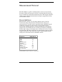
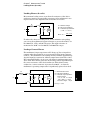
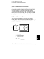
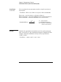
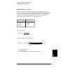
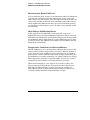
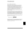
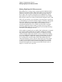
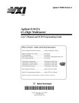
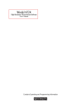
7 Agilent 34401A Multimeter TUTORIAL pages from User's Guide 7 Measurement Tutorial Measurement Tutorial The HP 34401A is capable of making highly accurate measurements. In order to achieve the greatest accuracy, you must take the necessary steps to eliminate potential measurement errors. This chapter describes common errors found in measurements and gives suggestions to help you avoid these errors. Thermal EMF Errors Thermoelectric voltages are the most common source of error in low-level dc voltage measurements. Thermoelectric voltages are generated when you make circuit connections using dissimilar metals at different temperatures. Each metal-to-metal junction forms a thermocouple, which generates a voltage proportional to the junction temperature. You should take the necessary precautions to minimize thermocouple voltages and temperature variations in low-level voltage measurements. The best connections are formed using copper-to-copper crimped connections. The table below shows common thermoelectric voltages for connections between dissimilar metals. Copper-toCopper Gold Silver Brass Beryllium Copper Aluminum Kovar or Alloy 42 Silicon Copper-Oxide Cadmium-Tin Solder Tin-Lead Solder Approx. mV / °C <0.3 0.5 0.5 3 5 5 40 500 1000 0.2 5 The HP 34401A’s input terminals are copper alloy. 198 Chapter 7 Measurement Tutorial Loading Errors (dc volts) Loading Errors (dc volts) Measurement loading errors occur when the resistance of the deviceunder-test (DUT) is an appreciable percentage of the multimeter’s own input resistance. The diagram below shows this error source. Rs HI Vs Ri Ideal Meter Vs = ideal DUT voltage Rs = DUT source resistance Ri = multimeter input resistance ( 10 MΩ or >10 GΩ ) Error (%) = LO 100 x Rs Rs + Ri To reduce the effects of loading errors, and to minimize noise pickup, you can set the multimeter’s input resistance to greater than 10 GΩ for the 100 mVdc, 1 Vdc, and 10 Vdc ranges. The input resistance is maintained at 10 MΩ for the 100 Vdc and 1000 Vdc ranges. Leakage Current Errors The multimeter’s input capacitance will “charge up” due to input bias currents when the terminals are open-circuited (if the input resistance is 10 GΩ). The multimeter’s measuring circuitry exhibits approximately 30 pA of input bias current for ambient temperatures from 0°C to 30°C. Bias current will double (×2) for every 8°C change in ambient temperature above 30°C. This current generates small voltage offsets dependent upon the source resistance of the device-under-test. This effect becomes evident for a source resistance of greater than 100 kΩ, or when the multimeter’s operating temperature is significantly greater than 30°C. Rs HI ib Vs Ri Ci Ideal Meter ib = multimeter bias current Rs = DUT source resistance Ci = multimeter input capacitance For DCV ranges: 0.1V, 1V, 10V: Ci < 700 pF 100V, 1000V: Ci < 50 pF For all ACV ranges: < 50 pF LO Error (v) ≅ ib x Rs 199 7 Chapter 7 Measurement Tutorial Rejecting Power-Line Noise Voltages Rejecting Power-Line Noise Voltages A desirable characteristic of integrating analog-to-digital (A/D) converters is their ability to reject spurious signals. Integrating techniques reject power-line related noise present with dc signals on the input. This is called normal mode rejection or NMR. Normal mode noise rejection is achieved when the multimeter measures the average of the input by “integrating” it over a fixed period. If you set the integration time to a whole number of power line cycles (PLCs) of the spurious input, these errors (and their harmonics) will average out to approximately zero. The HP 34401A provides three A/D integration times to reject power-line frequency noise (and power-line frequency harmonics). When you apply power to the multimeter, it measures the power-line frequency (50 Hz or 60 Hz), and then determines the proper integration time. The table below shows the noise rejection achieved with various configurations. For better resolution and increased noise rejection, select a longer integration time. Digits NPLCs Integration Time 60 Hz (50 Hz) 41⁄2 Fast 41⁄2 Slow 51⁄2 Fast 51⁄2 Slow 61⁄2 Fast 61⁄2 Slow 0.02 1 0.2 10 10 100 400 µs 16.7 ms 3 ms 167 ms 167 ms 1.67 sec 200 (400 µs) (20 ms) (3 ms) (200 ms) (200 ms) (2 sec) NMR – 60 dB – 60 dB 60 dB 60 dB Chapter 7 Measurement Tutorial Common Mode Rejection (CMR) Common Mode Rejection (CMR) Ideally, a multimeter is completely isolated from earth-referenced circuits. However, there is finite resistance between the multimeter’s input LO terminal and earth ground as shown below. This can cause errors when measuring low voltages which are floating relative to earth ground. HI Ideal Meter Vtest Rs LO Vf Ci Vf = float voltage Rs = DUT source resistance imbalance Ri = multimeter isolation resistance (LO-Earth) Ci = multimeter input capacitance: ≈200 pF (LO-Earth) Ri >10 GΩ Error ( v ) = Vf x Rs Rs + Ri Noise Caused by Magnetic Loops If you are making measurements near magnetic fields, you should take the necessary precautions to avoid inducing voltages in the measurement connections. You should be especially careful when working near conductors carrying large currents. Use twisted-pair connections to the multimeter to reduce the noise pickup loop area, or dress the test leads as close together as possible. Loose or vibrating test leads will also induce error voltages. Make sure your test leads are tied down securely when operating near magnetic fields. Whenever possible, use magnetic shielding materials or physical separation to reduce problem magnetic field sources. 7 201 Chapter 7 Measurement Tutorial Noise Caused by Ground Loops Noise Caused by Ground Loops When measuring voltages in circuits where the multimeter and the device-under-test are both referenced to a common earth ground, a “ground loop” is formed. As shown below, any voltage difference between the two ground reference points (Vground) causes a current to flow through the measurement leads. This causes errors, such as noise and offset voltage (usually power-line related), which are added to the measured voltage. The best way to eliminate ground loops is to maintain the multimeter’s isolation from earth; do not connect the input terminals to ground. If the multimeter must be earth-referenced, be sure to connect it, and the device-under-test, to the same common ground point. This will reduce or eliminate any voltage difference between the devices. Also make sure the multimeter and device-under-test are connected to the same electrical outlet whenever possible. RL HI Ideal Meter Vtest RL LO Ri >10 GΩ Vground RL = lead resistance Ri = multimeter isolation resistance Vground = voltage drop on ground bus 202 Chapter 7 Measurement Tutorial Resistance Measurements Resistance Measurements The HP 34401A offers two methods for measuring resistance: 2-wire and 4-wire ohms. For both methods, the test current flows from the input HI terminal and then through the resistor being measured. For 2-wire ohms, the voltage drop across the resistor being measured is sensed internal to the multimeter. Therefore, test lead resistance is also measured. For 4-wire ohms, separate “sense” connections are required. Since no current flows in the sense leads, the resistance in these leads does not give a measurement error. The errors mentioned earlier in this chapter for dc voltage measurements also apply to resistance measurements. Additional error sources unique to resistance measurements are discussed on the following pages. 4-Wire Ohms Measurements The 4-wire ohms method provides the most accurate way to measure small resistances. Test lead resistances and contact resistances are automatically reduced using this method. Four-wire ohms is often used in automated test applications where long cable lengths, numerous connections, or switches exist between the multimeter and the deviceunder-test. The recommended connections for 4-wire ohms measurements are shown below. See also “To Measure Resistance,” on page 17. HI HI-Sense R= Vmeter Itest Ideal Meter I test 7 LO-Sense LO 203 Chapter 7 Measurement Tutorial Removing Test Lead Resistance Errors Removing Test Lead Resistance Errors To eliminate offset errors associated with the test lead resistance in 2-wire ohms measurements, follow the steps below. 1. Short the ends of the test leads together. The multimeter displays the test lead resistance. 2. Press Null from the front panel. The multimeter displays “0” ohms with the leads shorted together. Power Dissipation Effects When measuring resistors designed for temperature measurements (or other resistive devices with large temperature coefficients), be aware that the multimeter will dissipate some power in the device-under-test. If power dissipation is a problem, you should select the multimeter’s next higher measurement range to reduce the errors to acceptable levels. The following table shows several examples. Range Test Current 100 Ω 1 kΩ 10 kΩ 100 kΩ 1 MΩ 10 MΩ 1 mA 1 mA 100 µA 10 µA 5 µA 500 nA DUT Power at Full Scale 100 µW 1 mW 100 µW 10 µW 30 µW 3 µW Settling Time Effects The HP 34401A has the ability to insert automatic measurement settling delays. These delays are adequate for resistance measurements with less than 200 pF of combined cable and device capacitance. This is particularly important if you are measuring resistances above 100 kΩ. Settling due to RC time constant effects can be quite long. Some precision resistors and multi-function calibrators use large parallel capacitors (1000 pF to 0.1 µF) with high resistor values to filter out noise currents injected by their internal circuitry. Non-ideal capacitances in cables and other devices may have much longer settling times than expected just by RC time constants due to dielectric absorption (soak) effects. Errors will be measured when settling after the initial connection and after a range change. 204 Chapter 7 Measurement Tutorial Errors in High Resistance Measurements Errors in High Resistance Measurements When you are measuring large resistances, significant errors can occur due to insulation resistance and surface cleanliness. You should take the necessary precautions to maintain a “clean” high-resistance system. Test leads and fixtures are susceptible to leakage due to moisture absorption in insulating materials and “dirty” surface films. Nylon and PVC are relatively poor insulators (109 ohms) when compared to PTFE Teflon insulators (1013 ohms). Leakage from nylon or PVC insulators can easily contribute a 0.1% error when measuring a 1 MΩ resistance in humid conditions. DC Current Measurement Errors When you connect the multimeter in series with a test circuit to measure current, a measurement error is introduced. The error is caused by the multimeter’s series burden voltage. A voltage is developed across the wiring resistance and current shunt resistance of the multimeter as shown below. Rs I Vb Vs R Ideal Meter LO Vs Rs Vb R = source voltage = DUT source resistance = multimeter burden voltage = multimeter current shunt Error ( % ) = −100% x Vb Vs 7 Teflon is a registered trademark of E.I. duPont deNemours and Co. 205 Chapter 7 Measurement Tutorial True RMS AC Measurements True RMS AC Measurements True RMS responding multimeters, like the HP 34401A, measure the “heating” potential of an applied voltage. Unlike an “average responding” measurement, a true RMS measurement is used to determine the power dissipated in a resistor. The power is proportional to the square of the measured true RMS voltage, independent of waveshape. An average responding ac multimeter is calibrated to read the same as a true RMS meter for sinewave inputs only. For other waveform shapes, an average responding meter will exhibit substantial errors as shown below. The multimeter’s ac voltage and ac current functions measure the ac-coupled true RMS value. This is in contrast to the ac+dc true RMS value shown above. Only the “heating value” of the ac components of the input waveform are measured (dc is rejected). For sinewaves, triangle waves, and square waves, the ac and ac+dc values are equal since these waveforms do not contain a dc offset. Non-symmetrical waveforms, such as pulse trains, contain dc voltages which are rejected by ac-coupled true RMS measurements. 206 Chapter 7 Measurement Tutorial Crest Factor Errors (non-sinusoidal inputs) An ac-coupled true RMS measurement is desirable in situations where you are measuring small ac signals in the presence of large dc offsets. For example, this situation is common when measuring ac ripple present on dc power supplies. There are situations, however, where you might want to know the ac+dc true RMS value. You can determine this value by combining results from dc and ac measurements as shown below. You should perform the dc measurement using at least 10 power line cycles of integration (6 digit mode) for best ac rejection. ac + dc = √ ac 2 + dc2 Crest Factor Errors (non-sinusoidal inputs) A common misconception is that “since an ac multimeter is true RMS, its sinewave accuracy specifications apply to all waveforms.” Actually, the shape of the input signal can dramatically affect measurement accuracy. A common way to describe signal waveshapes is crest factor. Crest factor is the ratio of the peak value to RMS value of a waveform. For a pulse train, for example, the crest factor is approximately equal to the square root of the inverse of the duty cycle as shown in the table on the previous page. In general, the greater the crest factor, the greater the energy contained in higher frequency harmonics. All multimeters exhibit measurement errors that are crest factor dependent. Crest factor errors for the HP 34401A are shown in the specifications in chapter 8. Note that the crest factor errors do not apply for input signals below 100 Hz when using the slow ac filter. 7 207 Chapter 7 Measurement Tutorial Crest Factor Errors (non-sinusoidal inputs) Crest Factor (continued) You can estimate the measurement error due to signal crest factor as shown below: Total Error = Error (sine) + Error (crest factor) + Error (bandwidth) Error (sine): error for sinewave as shown in chapter 8. Error (crest factor): crest factor additional error as shown in chapter 8. Error (bandwidth): estimated bandwidth error as shown below. Bandwidth Error = Example – C.F.2 x F 4 π x BW C.F. = signal crest factor F = input fundamental frequency BW = multimeter’s –3 dB bandwidth ( 1 MHz for the HP 34401A ) Calculate the approximate measurement error for a pulse train input with a crest factor of 3 and a fundamental frequency of 20 kHz. For this example, assume the multimeter’s 90-day accuracy specifications: ± (0.05% + 0.03%). Total Error = 0.08% + 0.15% + 1.4% = 1.6% 208 Chapter 7 Measurement Tutorial Loading Errors (ac volts) Loading Errors (ac volts) In the ac voltage function, the input of the HP 34401A appears as a 1 MΩ resistance in parallel with 100 pF of capacitance. The cabling that you use to connect signals to the multimeter will also add additional capacitance and loading. The table below shows the multimeter’s approximate input resistance at various frequencies. Input Frequency Input Resistance 1 MΩ 850 kΩ 160 kΩ 16 kΩ 100 Hz 1 kHz 10 kHz 100 kHz For low frequencies: Error (%) = − 100 x Rs Rs + 1 MΩ Additional error for high frequencies: Error (%) = 100 x 1 √1 + ( 2 π x F x R s x Cin )2 −1 Rs = source resistance F = input frequency Cin = input capacitance (100 pF) plus cable capacitance 7 209 Chapter 7 Measurement Tutorial Measurements Below Full Scale Measurements Below Full Scale You can make the most accurate ac measurements when the multimeter is at full scale of the selected range. Autoranging occurs at 10% and 120% of full scale. This enables you to measure some inputs at full scale on one range and 10% of full scale on the next higher range. The accuracy will be significantly different for these two cases. For highest accuracy, you should use manual range to get to the lowest range possible for the measurement. High-Voltage Self-Heating Errors If you apply more than 300 Vrms, self-heating will occur in the multimeter’s internal signal-conditioning components. These errors are included in the multimeter’s specifications. Temperature changes inside the multimeter due to self-heating may cause additional error on other ac voltage ranges. The additional error will be less than 0.02% and will dissipate in a few minutes. Temperature Coefficient and Overload Errors The HP 34401A uses an ac measurement technique that measures and removes internal offset voltages when you select a different function or range. If you leave the multimeter in the same range for an extended period of time, and the ambient temperature changes significantly (or if the multimeter is not fully warmed up), the internal offsets may change. This temperature coefficient is typically 0.002% of range per °C and is automatically removed when you change functions or ranges. When manual ranging to a new range in an overload condition, the internal offset measurement may be degraded for the selected range. Typically, an additional 0.01% of range error may be introduced. This additional error is automatically removed when you remove the overload condition and then change functions or ranges. 210 Chapter 7 Measurement Tutorial Low-Level Measurement Errors Low-Level Measurement Errors When measuring ac voltages less than 100 mV, be aware that these measurements are especially susceptible to errors introduced by extraneous noise sources. An exposed test lead will act as an antenna and a properly functioning multimeter will measure the signals received. The entire measurement path, including the power line, act as a loop antenna. Circulating currents in the loop will create error voltages across any impedances in series with the multimeter’s input. For this reason, you should apply low-level ac voltages to the multimeter through shielded cables. You should connect the shield to the input LO terminal. Make sure the multimeter and the ac source are connected to the same electrical outlet whenever possible. You should also minimize the area of any ground loops that cannot be avoided. A high-impedance source is more susceptible to noise pickup than a low-impedance source. You can reduce the high-frequency impedance of a source by placing a capacitor in parallel with the multimeter’s input terminals. You may have to experiment to determine the correct capacitor value for your application. Most extraneous noise is not correlated with the input signal. You can determine the error as shown below. Voltage Measured = √V in 2 + Noise 2 Correlated noise, while rare, is especially detrimental. Correlated noise will always add directly to the input signal. Measuring a low-level signal with the same frequency as the local power line is a common situation that is prone to this error. 7 211 Chapter 7 Measurement Tutorial Common Mode Errors Common Mode Errors Errors are generated when the multimeter’s input LO terminal is driven with an ac voltage relative to earth. The most common situation where unnecessary common mode voltages are created is when the output of an ac calibrator is connected to the multimeter “backwards.” Ideally, a multimeter reads the same regardless of how the source is connected. Both source and multimeter effects can degrade this ideal situation. Because of the capacitance between the input LO terminal and earth (approximately 200 pF for the HP 34401A), the source will experience different loading depending on how the input is applied. The magnitude of the error is dependent upon the source’s response to this loading. The multimeter’s measurement circuitry, while extensively shielded, responds differently in the backward input case due to slight differences in stray capacitance to earth. The multimeter’s errors are greatest for high- voltage, high-frequency inputs. Typically, the multimeter will exhibit about 0.06% additional error for a 100 V, 100 kHz reverse input. You can use the grounding techniques described for dc common mode problems to minimize ac common mode voltages (see page 201). AC Current Measurement Errors Burden voltage errors, which apply to dc current, also apply to ac current measurements. However, the burden voltage for ac current is larger due to the multimeter’s series inductance and your measurement connections. The burden voltage increases as the input frequency increases. Some circuits may oscillate when performing current measurements due to the multimeter’s series inductance and your measurement connections. 212 Chapter 7 Measurement Tutorial Frequency and Period Measurement Errors Frequency and Period Measurement Errors The multimeter uses a reciprocal counting technique to measure frequency and period. This method generates constant measurement resolution for any input frequency. The multimeter’s ac voltage measurement section performs input signal conditioning. All frequency counters are susceptible to errors when measuring low-voltage, low-frequency signals. The effects of both internal noise and external noise pickup are critical when measuring “slow” signals. The error is inversely proportional to frequency. Measurement errors will also occur if you attempt to measure the frequency (or period) of an input following a dc offset voltage change. You must allow the multimeter’s input dc blocking capacitor to fully settle before making frequency measurements. Making High-Speed DC and Resistance Measurements The multimeter incorporates an automatic zero measurement procedure (autozero) to eliminate internal thermal EMF and bias current errors. Each measurement actually consists of a measurement of the input terminals followed by a measurement of the internal offset voltage. The internal offset voltage error is subtracted from the input for improved accuracy. This compensates for offset voltage changes due to temperature. For maximum reading speed, turn autozero off. This will more than double your reading speeds for dc voltage, resistance, and dc current functions. Autozero does not apply to other measurement functions. 7 213 Chapter 7 Measurement Tutorial Making High-Speed AC Measurements Making High-Speed AC Measurements The multimeter’s ac voltage and ac current functions implement three different low-frequency filters. These filters allow you to trade-off low frequency accuracy for faster reading speed. The fast filter settles in 0.1 seconds, and is useful for frequencies above 200 Hz. The medium filter settles in 1 second, and is useful for measurements above 20 Hz. The slow filter settles in 7 seconds, and is useful for frequencies above 3 Hz. With a few precautions, you can perform ac measurements at speeds up to 50 readings per second. Use manual ranging to eliminate autoranging delays. By setting the preprogrammed settling (trigger) delays to 0, each filter will allow up to 50 readings per second. However, the measurement might not be very accurate since the filter is not fully settled. In applications where sample-to-sample levels vary widely, the medium filter will settle at 1 reading per second, and the fast filter will settle at 10 readings per second. If the sample-to-sample levels are similar, little settling time is required for each new reading. Under this specialized condition, the medium filter will provide reduced accuracy results at 5 readings per second, and the fast filter will provide reduced accuracy results at 50 readings per second. Additional settling time may be required when the dc level varies from sample to sample. The multimeter’s dc blocking circuitry has a settling time constant of 0.2 seconds. This settling time only affects measurement accuracy when dc offset levels vary from sample to sample. If maximum measurement speed is desired in a scanning system, you may want to add an external dc blocking circuit to those channels with significant dc voltages present. This circuit can be as simple as a resistor and a capacitor. 214