1
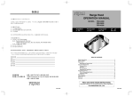
Range Hood
INSTALLATION MANUAL
MODEL: FSR-3000
FSR-3600
FSR-4200
TABLE OF CONTENTS
Safety Instructions .............................................................................................. 3
Name of Parts ..................................................................................................... 5
Size & Dimensions .............................................................................................. 5
Range Hood Location ......................................................................................... 6
Installation ........................................................................................................... 7
1. Preparation ................................................................................................ 7
2. Range Hood Mounting ............................................................................. 11
3. Connecting Power Supply Wires ............................................................. 12
4. Final Assembly and Check ...................................................................... 13
Explanation to the End User ............................................................................. 14
Circuit Diagram ................................................................................................. 14
READ AND SAVE THESE INSTRUCTIONS.
Keep this manual in a convenient place for future reference.
FUJI INDUSTRIAL CO., LTD.
1U030381
SAFETY INSTRUCTIONS
Before installation and operation, read these instructions carefully and use this product only in the manner
described by the manufacturer in the operation manual.
The instructions shown below are used to alert you to potential personal injury and property damage
hazards.
There are three hazard classifications based on potentially dangerous situations.
Obey all safety instructions that show these symbols to avoid possible injury, death and property damage.
WARNING: WARNING indicates a potentially hazardous situation which, if not avoided, could
result in death or serious injury.
CAUTION:
CAUTION indicates a potentially hazardous situation which, if not avoided, may
result in minor or moderate injury.
CAUTION:
CAUTION used without the safety alert symbol indicates a potentially hazardous
situation which, if not avoided, may result in property damage.
WARNING
1. TO REDUCE THE RISK OF FIRE, ELECTRIC SHOCK, OR INJURY TO PERSONS,
OBSERVE THE FOLLOWING:
a) Use this unit only in the manner intended by the manufacturer. If you have questions,
contact the manufacturer.
b) Before servicing or cleaning the unit, switch power off at service panel and lock the service
disconnecting means to prevent power from being switched on accidentally. When the
service disconnecting means cannot be locked, securely fasten a prominent warning device,
such as a tag, to the service panel.
2. To reduce the risk of fire or electric shock, do not use this product with any solid-state speed
control device.
3. TO REDUCE THE RISK OF FIRE, ELECTRIC SHOCK, OR INJURY TO PERSONS,
OBSERVE THE FOLLOWING:
a) Installation work and electrical wiring must be done by a qualified person(s) in accordance
with all applicable codes and standards, including fire-rated construction.
b) Sufficient air is needed for proper combustion and exhausting of gases through the flue
(chimney) of fuel burning equipment to prevent back drafting. Follow the heating equipment
manufacturer’s guidelines and safety standards such as those published by the National Fire
Protection Assoiation (NFPA), and The American Society for Heating, Refrigeration and Air
Conditioning Engineers (ASHRAE), and the local code authorities.
c) When cutting or drilling into wall or ceiling, do not damage electrical wiring and other hidden
utilities.
d) Ducted fan must always be vented to outdoors.
4. TO REDUCE THE RISK OF FIRE, USE ONLY METAL DUCTWORK.
5. This unit must be grounded.
6. Install this range hood to the cabinet. Check that the hood is correctly installed, since
incorrect installation could result in the range hood becoming detached and falling off.
7. Connect only to an AC120 Volt power source or the range hood could result in fire, electric
shock, and damage.
3
CAUTION
1. For general ventilating use only. Do not use to exhaust hazardous or explosive material
and vapors.
2. To reduce the risk of fire and to properly exhaust air, be sure to duct air outside. Do not
vent exhaust air into spaces within walls, ceilings or into attics, crawl spaces or garages.
3. Read specification label on this product for further information and requirements.
4. Use only for the purpose of kitchen ventilation.
5. Do not install this range hood in the bathroom or in other wet rooms since electrical shock
and damage may result.
6. Fasten the filter and other parts securely. Incorrect attachment may resulty in personal
injury or property damage.
7. Keep your hands and other objects away from the fan while it is in motion. The range hood
may injure you or damage itself.
NOTE: The safety instructions are explained with the following
pictographic symbols.
: means prohibition. It indicates actions, if any, that
mustn’t be done.
' : means forcible execution. It indicates actions, if any,
that must be done.
4
NAME OF PARTS
Filter
Body
Switch
Lamp Box
Fan Case Cover
Rectifier
Baffle Panel
Oil Catch Tray
Lamp Cover
Duct Joint
(rectangular)
Accessories
Washer Head
Wood Screw (× 6 pcs.)
Screw
(× 4 pcs.)
Soft Tape
(× 1 pc.)
Cover Plate
(× 1 pc.)
SIZE & DIMENSIONS
Dimensions (in inches)
Model
A
B
FSR-3000 30
27
FSR-3600 36
33
FSR-4200 42
39
(Unit : inch)
5
RANGE HOOD LOCATION
1
2
3
The range hood must be installed just above the cooktop.
4
Power requirements are:
The minimum distance from the cooking surface to the bottom of the range hood
must be 24”.
The total weight of the FSR series range hoods are:
FSR-3000 ---------- 16 kg
FSR-3600 ---------- 17 kg
FSR-4200 ---------- 18 kg
AC120 V, 60 Hz, 1.9 Amp
CAUTION: • Check that the hood is correctly installed, since incorrect
installation could result in the detachment of the range hood
and the unit fall off.
• To protect hands from injury, wear working gloves when
installing the range hood.
6
INSTALLATION
1. PREPARATION
WARNING: • If the range hood is not installed properly, it could become
detached and fall off.
• Ensure that the metal duct does not touch other metal
housing materials, otherwise fire or electric shock could result.
1
This range hood can discharge upward
or backward. According to the conditions
where the hood is installed, determine
whether it will discharge vertically (3¼" ×
10" or 7" Round) or horizontally (3¼" ×
10" only). For vertical or horizontal
discharge, run duct work between the
hood location and a roof cap or wall cap.
For the best results in either directions,
use a minimum number of transitions
and elbows. Be sure to attach a roof cap
or wall cap to avoid leaking rain in the
end.
2
Use diagrams below, for proper placement of ductwork and electrical cutout in
cabinet or wall.
; 3¼" × 10" Vertical Ducting
7
; 3¼" × 10" Horizontal Ducting
; 7" Round Vertical Ducting
8
3
4
Run house wiring between service panel and hood location.
Prepare the range hood.
(1) Remove the 7" round duct joint on the
top plate of the body by removing
2 fixing screws.
Note: Keep the screws for reusing later.
7" Round
Duct Joint
(2) Remove the Rectifier Baffle Panel by
loosening the screws, and dislocating
its temporary fixing holes from the screws.
Note: Use a screwdriver if they are tight.
Rectifier Baffle Panel
(3) Remove the fan case cover by removing
4 screws.
Fan Case Cover
9
×10" Vertical Discharge
; In Case of 3-1/4"×
Mount the supplied 3-1/4"×10" rectangular
duct joint on the top plate with 4 screws
(2 pieces: removed in Step 4-1, the others:
supplied).
Then attach the supplied soft tape around
the duct joint.
Soft Tape
Duct Joint
; In Case of 7" Round Vertical Discharge
First, remove half-cut circular part of the top
plate (duct knockout) using a hammer,
pliers, etc.
Mount the 7" round duct joint removed in
step (1) with 4 screws.
Then attach the supplied soft tape around
the duct joint.
Hit dented points
on the circular edge
Soft Tape
7" Round
Duct Joint
Duct
Knockout
CAUTION: • Wear working gloves to
Insert into
the holes
avoid injury.
• Do not apply excessive force
when removing the knockout.
The fan may be damaged.
×10" Horizontal Discharge
; In Case of 3-1/4"×
First, remove half-cut rectangular part of the
rear plate (duct knockout) using a hammer,
pliers, etc. Mount the supplied 3-1/4"×10"
rectangular duct joint with 2 screws.
Then attach the supplied soft tape around the
duct joint. To close the opening of the top
plate, attach the supplied cover plate with 2
screws.
Hit dented points
on the rectangular edge
Duct
Knockout
Cover Plate
Engage with
the notches
Duct Joint
10
2. RANGE HOOD MOUNTING
1
Referring to “SIZE & DIMENSIONS”,
insert 4 washer head wood screws into
the bottom plate of the cabinet. Marking
before screwing is recommended. Allow
about ¼" between the bottom plate and
screwheads for hanging the hood body.
2
With inserting the duct joint into the duct
end, hook the temporary fixing holes of
the body on the screws, then slide the
body backward until the screws are
engaged in narrow end of the holes.
3
After ensuring that the range hood is
positioned properly, tighten the 4 screws
and fix it firmly using 2 more washer
head wood screws.
Fixing Screws
4
Make the duct joint secure and air tight
using non-flammable tape such as duct
tape, etc. (not supplied)
Duct Tape, etc.
Duct
11
3. CONNECTING POWER SUPPLY WIRES
WARNING: • Electrical wiring should be done by a qualified person(s) in
accordance with all-applicable codes and standards,
including fire-rated construction. An unqualified person
doing the work could result in fire, electric shock or injury.
• This range hood uses 120V AC. Do not connect to another
voltage since fire, electric shock or damage could result.
1
Remove the nut from the conduit
connector at the end of power wiring.
Power
Wiring
Conduit
WARNING: Be sure to switch
power OFF at service panel
before wiring.
Nut
2
Connect the conduit through the
connecting hole of the body using the
nut previously removed.
Conduit
Range
Hood
Nut
12
3
Connect the electrical wires as follows:
Connect wires tightly and securely using
wire connectors (not supplied).
• Black to Black
• White to White
• Green to Green
Range Hood
Wire Connector
(not supplied)
Wire (unit side)
4
Conduit
Wire
(conduit side)
Make sure that all wires are connected
properly and enclosed inside of the
wiring compartment.
4. FINAL ASSEMBLY AND CHECK
Two 60 W light bulbs (not supplied) can be mounted to this range hood. Prior to final
assembly, install light bulbs (halogen or ordinary type, in the base diameter 26 mm),
rated 120 V - 60 W or below.
1
Assembly (refer to “PREPARATION”)
(1) Replace the fan case cover with 4 screws.
(2) Replace the Rectifier Baffle Panel with 2 screws.
(3) Install the oil catch tray.
2
Check
(1) Turn on the electrical circuit to the range hood.
(2) Make sure that the switch and light operate correctly.
Refer to page 5 of the Operation Manual.
(3) Check the ventilating functions at High (
), Medium (
) and Low (
)
positions.
(4) Make sure that the range hood has no abnormal noises and/or vibration.
CAUTION: • To reduce the risk of injury, keep your hands and other
objects away from the fan while it is in motion.
• Wear working gloves to avoid injury.
13
Explanation to the End User
(1) Referring to the Operation Manual, explain the operation of this range hood to
end users.
(2) The Installation Manual and Operation Manual should be given to the end user.
CIRCUIT DIAGRAM
Indicating Lamp
Control Switch
AC125V 3A
Lock
Main Coil 3 Thermal
Cutoffs
Main Coil 2
Main Coil 1
Red
Yellow
Red
White
Orange
Brown
Blue
Auxiliary Coil
Connector
Model No.1U201361
Capacitor Running Induction Motor
Single-phase 120V 60Hz 100W
Ins.Class A 4 Poles
14
Gray
Gray
Brown
Blue
Brown
Blue
Gray
Black
White
Green
Black
Red
Orange
Black
Black
White
Black
Black
Connector
Capacitor
7µF 250VAC
Reset Key
Red
Orange
120V
60Hz
60W
White
White
White
60W
Lock Release
Yellow
Yellow
Lamp receptacle E26
(Lamp Max 60W)
Connector
Fuji Industrial Co., Ltd.
2-1-9 Fuchinobe, Sagamihara-shi, Kanagawa-ken 229-0006 Japan
Tel. +81-42-753-1001
Fax. +81-42-753-1009
1U030381