1
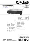
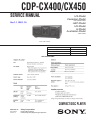
CDP-CX400/CX450
SERVICE MANUAL
US Model
Canadian Model
CDP-CX400/CX450
Ver 1.1 2001. 10
AEP Model
UK Model
E Model
Australian Model
CDP-CX450
Photo; CDP-CX400
Model Name Using Similar Mechanism
NEW
CD Mechanism Type
CDM62-K1BD35A
Base Unit Type
BU-K1BD35A
Optical Pick-up Type
KSM-213BFN
SPECIFICATIONS
USA, Canadian
Europian
230 V AC, 50/60 Hz
COMPACT DISC PLAYER
9-929-232-12
Sony Corporation
2001J1600-1
© 2001.10
Home Audio Company
Published by Sony Engineering Corporation
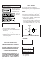
Laser component in this product is capable of emitting radiation
exceeding the limit for Class 1.
This appliance is classified as
a CLASS 1 LASER product.
The CLASS 1 LASER
PRODUCT MARKING is
located on the rear exterior.
The following
caution label is
located inside of
the unit.
CAUTION
Use of controls or adjustments or performance of procedures
other than those specified herein may result in hazardous
radiation exposure.
Notes on chip component replacement
• Never reuse a disconnected chip component.
• Notice that the minus side of a tantalum capacitor may be
damaged by heat.
Flexible Circuit Board Repairing
• Keep the temperature of soldering iron around 270˚C
during repairing.
• Do not touch the soldering iron on the same conductor of the
circuit board (within 3 times).
• Be careful not to apply force on the conductor when soldering
or unsoldering.
SAFETY CHECK-OUT
After correcting the original service problem, perform the following
safety checks before releasing the set to the customer:
Check the antenna terminals, metal trim, “metallized” knobs, screws,
and all other exposed metal parts for AC leakage. Check leakage as
described below.
LEAKAGE
The AC leakage from any exposed metal part to earth Ground and
from all exposed metal parts to any exposed metal part having a
return to chassis, must not exceed 0.5 mA (500 microampers).
Leakage current can be measured by any one of three methods.
1. A commercial leakage tester, such as the Simpson 229 or RCA
WT-540A. Follow the manufacturers’ instructions to use these
instruments.
2. A battery-operated AC milliammeter. The Data Precision 245
digital multimeter is suitable for this job.
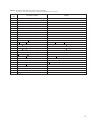
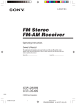
3. Measuring the voltage drop across a resistor by means of a
VOM or battery-operated AC voltmeter. The “limit” indication
is 0.75 V, so analog meters must have an accurate low-voltage
scale. The Simpson 250 and Sanwa SH-63Trd are examples of
a passive VOM that is suitable. Nearly all battery operated
digital multimeters that have a 2V AC range are suitable. (See
Fig. A)
To Exposed Metal
Parts on Set
0.15µF
1.5kΩ
Earth Ground
Fig. A. Using an AC voltmeter to check AC leakage.
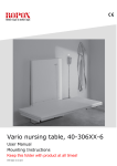
MODEL IDENTIFICATION
— BACK PANEL —
SAFETY-RELATED COMPONENT WARNING !!
COMPONENTS IDENTIFIED BY MARK ! OR DOTTED LINE
WITH MARK ! ON THE SCHEMATIC DIAGRAMS AND IN
THE PARTS LIST ARE CRITICAL TO SAFE OPERATION.
REPLACE THESE COMPONENTS WITH SONY PARTS
WHOSE PART NUMBERS APPEAR AS SHOWN IN THIS
MANUAL OR IN SUPPLEMENTS PUBLISHED BY SONY.
ATTENTION AU COMPOSANT AYANT RAPPORT
À LA SÉCURITÉ!!
LES COMPOSANTS IDENTIFIÉS PAR UNE MARQUE ! SUR
LES DIAGRAMMES SCHÉMATIQUES ET LA LISTE DES
PIÈCES SONT CRITIQUES POUR LA SÉCURITÉ DE
FONCTIONNEMENT. NE REMPLACER CES COMPOSANTS
QUE PAR DES PIÈCES SONY DONT LES NUMÉROS
SONT DONNÉS DANS CE MANUEL OU DANS LES
SUPPLÉMENTS PUBLIÉS PAR SONY.
2
AC
voltmeter
(0.75V)
PART NO.
PARTS No.
4-226-838-0π
4-226-838-1π
4-226-838-2π
4-226-838-3π
4-226-838-4π
4-226-838-5π
4-226-838-6π
MODEL
CX400 : US
CX400 : CND
CX450 : US
CX450 : CND
CX450 : AEP, UK
CX450 : AUS
CX450 : SP, MY
• Abbreviation
CND : Canadian model
AUS : Australian model
SP : Singapore model.
MY : Malaysia model.
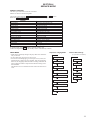
SECTION 1
SERVICE NOTE
TABLE OF CONTENTS
1. SERVICING NOTE .......................................................... 3
2. GENERAL .......................................................................... 6
3. DISASSEMBLY
3-1.
3-2.
3-3.
3-4.
3-5.
3-6.
3-7.
3-8.
Upper Case Assembly ··················································· 7
Main Board Assembly ··················································· 7
Front Panel Assembly ···················································· 8
Table (400) Assembly ···················································· 8
Base (Door, Driving) Assembly ···································· 9
Pop-up Assembly ··························································· 9
Back Panel Assembly ·················································· 10
CDM Assembly ·························································· 10
4. SERVICE MODE ............................................................. 11
5. TEST MODE ..................................................................... 15
5-1. ADJ Mode ··································································· 15
5-2. Key and Display Check Mode ····································· 15
6. ADJUSTMENTS
6-1. Mechanical Adjustments ············································· 16
6-2. Electrical Adjustment ·················································· 18
NOTES ON HANDLING THE OPTICAL PICK-UP BLOCK
OR BASE UNIT
The laser diode in the optical pick-up block may suffer electrostatic
break-down because of the potential difference generated by the
charged electrostatic load, etc. on clothing and the human body.
During repair, pay attention to electrostatic break-down and also
use the procedure in the printed matter which is included in the
repain parts.
The flexible board is easily damaged and should be handled with
care.
NOTES ON LASER DIODE EMISSION CHECK
The laser beam on this model is concentrated so as to be focused on
the disc reflective surface by the objective lens in the optical pickup block. Therefore, when checking the laser diode emission,
observe from more than 30 cm away from the objective lens.
The emission check enables continuous checking of the S curve.
LASER DIODE AND FOCUS SEARCH OPERATION
CHECK
Carry out the “S curve check” in “CD section adjustment” and check
that the S curve waveform is output three times.
7. DIAGRAMS
7-1. Circuit Boards Location ·············································· 20
7-2. Block Diagrams
• BD Section ································································ 21
• Main Section ····························································· 22
7-3. Schematic Diagram – BD Section – ···························· 24
7-4. Printed Wiring Board – BD Section – ························· 25
7-5. Printed Wiring Board – Main Section – ······················ 26
7-6. Schematic Diagram – Main (1/2) Section – ················ 27
7-7. Schematic Diagram – Main (2/2) Section – ················ 28
7-8. Printed Wiring Board – T. Sens Section – ··················· 29
7-9. Schematic Diagram – Sensor Section – ······················ 29
7-10. Schematic Diagram – Display Section – ···················· 30
7-11. Printed Wiring Board – Display Section – ·················· 31
7-12. Schematic Diagram – Jog Section – ··························· 32
7-13. Printed Wiring Board – Jog Section – ························ 33
7-14. Schematic Diagram – Power Section – ······················· 34
7-15. Printed Wiring Board – Power Section – ···················· 35
7-16. IC Block Diagrams ····················································· 36
7-17. IC Pin Functions ························································· 37
8. EXPLODED VIEWS
8-1.
8-2.
8-3.
8-4.
8-5.
8-6.
8-7.
Case Section ································································ 42
Chassis Section ···························································· 43
Front Panel Section ····················································· 44
Mechanism Section 1 (CDM54-K1BD35E) ··············· 45
Mechanism Section 2 (CDM54-K1BD35E) ··············· 46
Mechanism Section 3 (CDM54-K1BD35E) ··············· 47
Opeical Pick-up Section (KSM-213BFN/M-NP) ········ 48
9. ELECTRICAL PARTS LIST ........................................ 49
3
CD-TEXT TEST DISC
This unit is able to display the TEXT data (character information) written in the CD on its fluorescent indicator tube.
The CD-TEXT TEST DISC (TGCS-313:J-2501-126-A) is used for checking the display.
To check, perform the following procedure.
Checking Method:
1. Turn ON the power, set the disc on the disc table with the side labeled as “test disc” as the right side, close the front cover, and chuck the
disc.
2. The following will be displayed on the fluorescent indicator tube. (The display switches each time the TIME/TEXT button is pressed.)
Display : CD TEXT TEST DISC (Album Title)
3. Press the · button and play back the disc.
4. The following will be displayed on the fluorescent indicator tube. (If nothing is displayed, press the TIME/TEXT button.)
Display : 1kHz/0 dB/ L&R
5. Rotate ≠ and ± knob to switch the track. The text data of each track will be displayed.
For details of the displayed contents for each track, refer to “Table 1 : CD-TEXT TEST DISC Text Data Contents” and “Table 2 : CDTEXT TEST DISC Recorded Contents and Display”.
Restrictions in CD-TEXT Display
In this unit, some special characters will not be displayed properly. These will be displayed as a space or a character resembling it. For details,
refer to “Table 2 : CD-TEXT DISC Recorded Contents and Display”.
Table 1 : CD-TEXT TEST DISC Text Data Contents (TRACKS No. 1 to 41:Normal Characters)
TRACK
No.
Displayed Contents
TRACK
No.
Displayed Contents
1
1kHz/0dB/L&R
22
1kHz/-90dB/L&R
2
20Hz/0dB/L&R
23
Infinity Zero w/o emphasis//L&R
3
40Hz/0dB/L&R
24
Infinity Zero with emphasis//L&R
4
100Hz/0dB/L&R
25
400Hz+7kHz(4:1)/0dB/L&R
5
200Hz/0dB/L&R
26
400Hz+7kHz(4:1)/-10dB/L&R
6
500Hz/0dB/L&R
27
19kHz+20kHz(1:1)/0dB/L&R
7
1kHz/0dB/L&R
28
19kHz+20kHz(1:1)/-10dB/L&R
8
5kHz/0dB/L&R
29
100Hz/0dB/L*
9
7kHz/0dB/L&R
30
1kHz/0dB/L*
10
10kHz/0dB/L&R
31
10kHz/0dB/L*
11
16kHz/0dB/L&R
32
20kHz/0dB/L*
12
18kHz/0dB/L&R
33
100Hz/0dB/R*
13
20kHz/0dB/L&R
34
1kHz/0dB/R*
14
1kHz/0dB/L&R
35
10kHz/0dB/R*
15
1kHz/-1dB/L&R
36
20kHz/0dB/R*
16
1kHz/-3dB/L&R
37
100Hz Squer Wave//L&R
17
1kHz/-6dB/L&R
38
1kHz Squer Wave//L&R
18
1kHz/-10dB/L&R
39
1kHz w/emphasis/-0.37dB/L&R
19
1kHz/-20dB/L&R
40
5kHz w/emphasis/-4.53dB/L&R
20
1kHz/-60dB/L&R
41
16kHz w/emphasis/-9.04dB/L&R
21
1kHz/-80dB/L&R
NOTE : The contents of Track No. 1 to 41 are the same as those of the current TEST DISC-their titles are displayed.
4
Table 2: CD-TEXT TEST DISC Recorded Contents and Display
(In this unit, some special characters cannot be displayed. This is no a fault.)
TRACK
No.
Recorded contents
Display
42
! ” # $ %& ´
(21h to 27h)1kHz 0dB L&R
N All the same
43
( )
*+ , – . /
(28h to 2Fh)
N All the same
44
012345 67
(30h to 37h)
N All the same
45
89 : ; <=>?
(38h to 3Fh)
N All the same
46
@A B C D E F G
(40h to 47h)
N All the same
47
H I J K L MNO
(48h to 4Fh)
N All the same
48
P Q R S T U V W (50h to 57h)
N All the same
49
XYZ [ ¥ ] ^ _
(58h to 5Fh)
X Y Z [ \ ] ^ _ (58····
50
′
ab c de f g
(60h to 57h)
N All the same
51
h i j k l mn o
(68h to 6Fh)
N All the same
52
pq r s t u vw
(70h to 77h)
N All the same
53
x y z { I } ~
(78h to 7Fh)
x y z { I } ~
(78····
54
i ¢£¤¥ §
≥ C ª ¬ PR –
(A0h to A7h) 8859-1
i ¢£¤¥
(A0····
(A8h to AFh)
≥
55
′
µ¶ •
1
4
1
2
′
§
µ
is not displayed
(A8···· C ª ¬ PR– are not displayed
•
±
57
†
1
¿
(B8h to BFh)
†
58
À Á Â Ã Ä Å ÆÇ
(C0h to C7h)
N All the same
59
ÈÉÊË Ì Í Î Ï
(C8h to CFh)
N All the same
60
(D0h to D7h)
61
D ÑÒÓÔÕÖ
Ø Ù Ú Û Ü Y˙ ß
(D8h to DFh)
N All the same
˙ ß (D8····
ΦÙÚÛÜY
62
à á â ã ä åæç
(E0h to E7h)
N All the same
63
èéêë ì í î ï
(E8h to FFh)
N All the same
64
∂ ñòóôõ ö÷
(F0h to F7h)
o ñ ò ó ô õ ö ÷ (F0····
65
ø ù ú û ü y´
(F8h to FFh)
N All the same
66
No.66
N All the same
67
No.67
N All the same
56
to
99
2
º
to
No.99
3
3
4
ÿ
(B0h to B7h)
• (B0····
•
¿ (B8····
1
±
º
2
3
1
4
¶ are not displayed
1
2
3
4
are not displayed
to
N All the same
5
SECTION 2
GENERAL
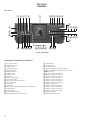
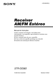
Front Panel
q;qaqs qd qf qg
9
45 6 7 8
qh
3
qj qk ql w;
2
1
r;
wa ws wd wf
wg
el
ekejehegef
ed es eae; wl
wk wjwh
Photo: CDP-CX400
LOCATION OF PARTS AND CONTROLS
1
2
3
4
5
6
7
8
9
q;
qa
qs
qd
qf
qg
qh
qj
qk
ql
w;
6
1/u (power) button
STANDBY indicator
Display window
CONTINUE button
SHUFFLE button
PROGRAM button
REPEAT button
SCROLL button
Front cover
OPEN/CLOSE button
DISC EJECT button
EASY PLAY button and indicator
MENU/NO button
+100 button
YES button
DISC/CHARACTER/PUSH ENTER knob and button
CHECK button
CLEAR button
NAME SEARCH button
ARTIST MODE button and indicator
wa
ws
wd
wf
wg
wh
wj
wk
wl
e;
ea
es
ed
ef
eg
eh
ej
ek
el
r;
FADER button
X-FADE button
NO DELAY button
MEGA CONTROL button and indicator
≠ AMS ±/PUSH ENTER knob and button
p (stop) button
· (play) button and indicator
P (pause) button and indicator
HIT LIST button and indicator
GROUP 4 button and indicator
GROUP 3 button and indicator
GROUP 2 button and indicator
GROUP 1 button and indicator
GROUP FILE button
GROUP 8 button and indicator
GROUP 7 button and indicator
GROUP 6 button and indicator
GROUP 5 button and indicator
KEYBOARD jack
TIMER OFF/PLAY switch
SECTION 3
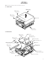
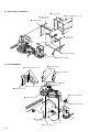
DISASSEMBLY
Note : Follow the disassembly procedure in the numerical order given.
3-1. UPPER CASE
1 Three screws
(case 3 screw)
2 Two screws
@(case 3 screw)
3 Two screws
@(case 3 screw)
5 Upper Case
4 Two screws
@(case 3 screw)
3-2. MAIN BOARD
qa MAIN board
0 Four screws
(BVTP 3 × 8)
7 Flat type wire
(CN502)(15 core)
qs Flat type wire
(CN501)(23 core)
3 Connector (CN901)
1 Two screws (BVTP 3 × 8)
8 Two connectors
(CN505, CN506)
2 Bracket (R)
9 Three screws
(BVTP 3 × 8)
qd Two screws
(BVTP 3 × 8)
4 Three connectors
(CN503, CN801, CN903)
qf Blacket (L)
5 Connector (CNP902)
6 Connector (CNP504)
7
3-3. FRONT PANEL ASSEMBLY
1 Connector (CNP503)
2 Screw (BVTP 3 × 8)
5 Remove the claw
3 Two screws
(BVTP 3 × 8)
6 Remove the claw
7 Front panel assembly
4 Three screws
(BVTP 3 × 8)
3-4. TABLE (400) ASSEMBLY
3 Table (400) assembly
1 Screw (BVTP 3 × 16)
2 Guide (door)
4 Washer
8
3-5. BASE (DOOR DRI VING) ASSEMBLY
1 Two screws
(BVTP 3 × 8)
5 Cover (table)
4 Three screws (BVTP 3 × 8)
2 Cover (PT)
9 Base (door driveing)
assembly
6 Door assembly
3 Connector (CN602)
7 Two screws (BVTP 3 × 8)
8 Eight screws (BVTP 3 × 8)
3-6. POP-UP ASSEMBLY
2 Step screw
3 Pop-up assembly
1 Screw (PTPWH 3 × 6)
9
3-7. BACK PANEL ASSEMBLY
2 Cover (CDM)
1 Nine screws (BVTP 3 × 8)
3 Three screws
(BVTP 3 × 8)
4 Bracket (CDM)
6 Four screws
(BVTP 3 × 8)
7 Back panel assembly
5 Connector (CN991)
3-8. CDM ASSEMBLY
5 Magnet assembly
6 Washer
3 Six screws (BVTP 3 × 8)
8 CD mechanism
7 Spring
9 Washer
4 Bracket (top 400)
1 Connector (CN603)
qd CDM assembly
2 Connector (CN601)
0 Four screws
(BVTP 3 × 8)
qs Seven screws
(BVTP 3 × 8)
qa Screw (PSW 3 × 8)
10
SECTION 4
SERVICE MODE
SPECIAL FUNCTION
This unit is provided with several service modes.
Details are shown in the following table.
Turn on the power and press GROUP FILE , MEGA CONTROL and 1/u buttons.
Rotate the DISC/CHARACTER dial to enter any of the following modes.
Display
Mech Adjust
Table Roatation
All Lit Mode
Ship Mode
Normal Aging
Table Aging
Door Popup Aging
Color Bar (OSD)
Test Disp (OSD)
Memo Copy Mode
Model Name
Show Mcom Ver.
Demo
BUS Check
M kentou
Mechanism adjustment mode
Mode in which table keeps rotating
All lights ON mode
Default mode
Normal aging mode
Table aging mode
Door/popup aging mode
Color bar on OSD
TEST DISPLAY for OSD
Memo copy mode
Model name display
Software version display
400-memo writing mode
Bus check
Loading aging
To exit the mode, press 1/u button to enter the standby state.
(When selecting the Ship mode, the standby mode is automatically entered.)
AGING MODE
• Mode which repeatedly changes and plays back discs automatically in the unit.
• It will repeat aging as long as no errors occur.
• If an error occurs during aging, it will stop all servos, motors, etc.
instantaneously, display the error number, and stop operations.
However, the stopping conditions differ according to whether the
unit is equipped with the “self-protection function during errors”
described later.
The function serves to maintain the state of the unit when errors
occur.
Sequence of Aging Mode
1.
2.
3.
4.
5.
Order of Disc Change
(1 cycle takes 3 minutes)
$
Disc change
$
Load in
$
TOC read
$
Access of last track
$
3 second playback
6.
$
Access of first track
7.
$
3 second playback
8.
$
Load out
1.
$
No. 80
2.
$
No. 320
3.
$
No. 240
4.
$
No. 400
5.
$
No. 160
$
$
11
Special Aging Mode Functions
The aging mode is provided with the following convenient functions
• Disc setting mode (*1)
• Selection of presence of protection function during error (*2)
• Count function of aging cycle (*3)
*1 Disc setting mode:
5 discs are set before setting the aging mode. This mode makes
the setting of these discs more easy.
*2 Self protection function during errors:
Function which voluntarily corrects errors which occur during
normal operations by retries.
If this function is not provided, all operations will be stopped
without retiring. It is suitable for checking errors with low
reproducibility.
If this function is provided, and errors can be corrected by
retries, aging will be continued without stopping.
*3 Aging cycle count function:
Functions which displays the number of agings carried out on
the Fluorescent indicator tube in numbers. One aging cycle
consists of five discs.
Aging Procedure
1. Turn on the power and press the GROUP FILE , MEGA
CONTROL and 1/u buttons.
2. Rotate DISC/CHARACTER dial, select “Normal Aging” and
press the dial to start the aging mode.
3. When the disc set mode is set, the · and P LEDs blink.
4. Rotate the DISC/CHARACTER dial. The slits (No. 80, 160,
400, 240, 320) for setting the discs will come forward. Insert
the discs into these slits. Do not set the discs in other slits.
5. Set whether the self-protection function during errors is
equipped with the unit. Press the REPEAT button. If
“REPEAT” is displayed on the Fluorescent indicator tube, it
means the function is provided. If “REPEAT” is not displayed,
it means the function is not provided.
6. Press the · button.
7. The · LED blinks, the aging mode is set, and aging is started.
8. The aging cycle lasts 3 minutes. If errors occur during aging,
the error number will be displayed on the Fluorescent indicator
tube. (Refer to the following table for the details of the errors.)
9. Aging will be repeated as long as no errors occur.
10. After each aging cycle, the number displayed on the Fluorescent
indicator tube will increase.
11. To end aging, to end aging, press the 1/u button to enter the
standby mode.
Error code
Code number
Name
Contents
#Err 01
DISC sensor check 1
No disc in the specified slit
#Err 02
DISC sensor check 2
Disc in other slits
#Err 03
Table operation check 1
Table motor current over
#Err 04
Table operation check 2
No table sensor input
#Err 05
Loading operation check 1
Load in timeover
#Err 06
Loading operation check 2
Load out timeover
#Err 08
Table is not stopped within the specified time.
#Err 09
Stopped while both T.SENS 1 and 2 are “LOW”.
#Err *1
BU related check 1
Access timeover
#Err *2
BU related check 2
During high speed playback, COUNT timeout
#Err *3
BU related check 3
Q data read error
#Err *4
BU related check 4
]BU operation (from focus search to until signal can be read) timeover
#Err *5
BU related check 5
GFS monitor error
#Err *6
BU related check 6
Focus cannot be imposed by focus search
The * numbers mean the following according to the state of the unit during aging
2 : From chucking to end of TOC read
3 : From end of TOC read to end of last track playback
4 : From end of last track playback to end of first track playback
# : DISC No.
12
TABLE AGING MODE
• This mode is used for rotating the table randomly.
• Aging will be performed continuously unless an error occurs.
• When an error occurs, the error code will be displayed on the
fluorescent indicator tube.
Procedure:
1. Turn on the power and press the GROUP FILE , MEGA
CONTROL and 1/u buttons.
Rotate the DISC/CHARACTER dial, select “Table Aging”
and press the dial.
Rotate the DISC/CHARACTER dial and set the disk in the
slit whose number is being displayed (150, 149, 300, 1, 2)
2. When the mode is set, both the · and P indicators will
start to blink.
3. When the · button is pressed, only the · indicator will
blink and aging starts.
4. To end the mode, press the 1/u button or disconnect the
power cord from the outlet.
During aging, operations will be carried out sequentially in the order
of No. 1, No. 2, No. 150, No. 149, and No. 300 slits.
The error codes displayed during operations and when errors occur
are the same as the “AGING MODE” described earlier.
DOOR POP UP AGING MODE
• This mode is used for performing aging of the CD pop up part
and door open/close.
It is used for checking if operations are performed normally.
Method:
1. Turn on the power and press the GROUP FILE , MEGA
CONTROL and 1/u buttons.
Rotate the DISC/CHARACTER dial, select “Door Popup
Aging” and press the dial.
2. Aging starts, and door open/close and up/down operations of
the pop up part are performed continuously.
3. To end the mode, press the 1/u button.
TABLE ROTATION MODE
• This mode is used for electrical adjustments. Refer to the section
on Electrical Adjustments.
$
COMMAND MODE: CD3
$
The error codes displayed during operations and when errors occur
are the same as the “AGING MODE” described earlier.
This unit
(Copy source)
$
Procedure:
1. Set a disc in the DISC 1 slit.
2. Turn on the power and press the GROUP FILE , MEGA
CONTROL and 1/u buttons.
Rotate the DISC/CHARACTER dial, select “Table Roatation”
and press the dial.
3. When the mode is set, both the · and P indicators will
start to blink.
4. When the · button is pressed, only the · indicator will
blink and aging starts.
5. To end the mode, press the 1/u button or disconnect the
power cord from the outlet.
TITLE MEMO SHIFT MODE
• This mode is used for writing title memo information recorded in
this unit in a different unit.
Use it for transferring disc memo contents written by the customer to the new units when replacing the unit, etc.
Connection:
Flow of data
$
LOADING AGING MODE
• This mode is used for repeating loading operations continuously.
• Aging will be performed continuously unless an error occurs.
• When an error occurs, the error code will be displayed on the
fluorescent indicator tube.
Another unit
(Copy destination)
COMMAND MODE: CD1
CONTROL A1 II connection cord provided
CONTROL A1 II
Procedure:
1. Connect two units using the CONTROL A1 II connection
cord shown in the figure.
2. Set the COMMAND MODE switch of the copy source unit to
CD3 and the COMMAND MODE switch of the copy
destination unit to CD1 .
3. With the power on, while pressing the GROUP 7 button and
§ OPEN/CLOSE button of the copy destination unit, press
the +100 button.
4. When the data has been transferred, the fluorescent indicator
tube displays “complete” for about 1 second.
MODEL NAME DISPLAY
•
Model names can be displayed on the fluorescent indicator tube
for checking the microprocessor model setting, etc.
Procedure:
With the power ON, while pressing the GROUP FILE and MEGA
CONTROL buttons, press the 1/u button.
Rotate the DISC/CHARACTER dial, select “Model Name”
and press the dial.
The model name is displayed on the fluorescent indicator tube.
Let the model name be displayed for three seconds and exit the
mode.
MICROPROCESSOR VERSION DISPLAY
•
The microprocessor version can be displayed on the fluorescent
indicator tube.
Procedure:
With the power ON, while pressing the GROUP FILE and MEGA
CONTROL buttons, press the 1/u button.
Rotate the DISC/CHARACTER dial, select “Show Mcom Ver.”
and press the dial.
The microprocessor version is displayed on the fluorescent indicator
tube.
Let the model name be displayed for three seconds and exit the
mode.
ALL LIT MODE
•
This mode is used for lighting the whole fluorescent indicator
tubes and LEDs.
Procedure:
With the power ON, while pressing the GROUP FILE and MEGA
CONTROL buttons, press the 1/u button.
Rotate the DISC/CHARACTER dial, select “All Lit Mode” and
press the dial.
Both the fluorescent indicator tubes and LEDs will light up
completely.
To end this mode, press the 1/u mode.
13
MECHANISM ADJUSTMENT MODE
•
This mode is used for mechanism adjustments. Refer to the
section on Mechanism Adjustments.
SHIPMENT MODE
•
This mode is used for setting the unit to the shipment state.
Do not execute it without a proper reason as it erases the
memory of the title memo recorded by the customer.
Procedure:
Set the TIMER switch to OFF . Next, with the power ON, while
pressing the GROUP FILE button and MEGA CONTROL button,
press the 1/u button. If the switch state is normal, the model name
will be displayed on the fluorescent indicator tube and the unit will
set into the shipment mode.
If the various switches are not set to their designated positions, error
will be displayed on the fluorescent indicator tube.
TITLE MEMO RECORDING CHECK MODE
This mode is not required for servicing. Do not execute without a
proper reason.
If executed, the memory of the title memo recorded by the customer
will be erased.
14
SECTION 5
TEST MODE
5-1. ADJ Mode
5-2. Key and Display Check Mode
1.
To set this mode, connect the test point (AFADJ) on the MAIN
board to Ground, and connect the power supply plug to the outlet.
2.
3.
Turn ON the power of the unit, set disc to disc table, and perform
chucking.
Disconnect the power supply plug from the outlet.
To set ADJ mode, connect the test point (ADJ) of the MAIN
board to Ground, and connect the power supply plug to the
outlet.
In this mode, table rotation and loading operations are not performed
because it is taken that the disc has already been chucked.
Note: The same operations are also performed in the following when
the test point (ADJ) is connected to Ground after turning on
the power.
• Direct search (movement of sledding motor) is not performed during accessing
• Ignored even when GFS becomes L
• Ignored even when the Q data cannot be read
• Focus gain does not decrease
ADJ Mode Special Functions Table
(The buttons shown with ( ) function by using the supplied remote commander only)
Button
Function
CONTINUE
Servo average display
Displays VC, FE, RF, TE and traverse in hexadecimal
numbers
SHUFFLE
PROGRAM
Focus bias display
Each time this is pressed, the focus bias is
switched
between 1 and 2
(1)
Bias actually set Optimum bias Minimum jitter
(2)
+:Upper aliasing bias -:Lower aliasing bias
Auto gain display
Displays focus, tracking, sledding in
hexadecimal
numbers
GROUP 3 (3)
Turns off the tracking and sledding servo
GROUP 8 (8)
Turns on the tracking and sledding servo
CHECK
S-JI mode.
(Exits this mode when the 1/u button is pressed.)
To end the ADJ mode
1. Press the 1/u button and disconnect the plug.
2. Remove the wire between ADJ and GND.
Note: When this mode is executed, all title memos recorded will be
erased.
• When this button is pressed, “line # No. #” will be displayed.
However, these will not be displayed for the following special
buttons. However, these will not be displayed for the following
special buttons.
p (stop) button: FL segment check
(Refer to FL Tube Check Patterns)
P (pause) button: FL grid check
(Refer to FL Tube Check Patterns)
The P LED also lights up simultaneously.
· (play) button: All FL segment and grid will light up.
· LED also lights up simultaneously.
TIMER switch:
When the switch position is PLAY , the
STANDBY LED lights up. It goes OFF
when set to OFF .
Each time this button is pressed, the value of the “Got ## keys”
increases. Buttons pressed once will not be counted when pressed
again.
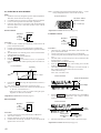
FL Tube Check Patterns
Magnified
Segment check
Grid check
A
B
C
D
E
F
G
• When the jog dial and AMS is rotated to the right, the GROUP
LEDs light up in the order of 1n2..8nHIT LISTnEASY PLAY
ARTIST MODE nMEGA CONTROLn1.
• When the jog dial and AMS is rotated to the left, the GROUP
LEDs light up in the order of 8n7..1 nMEGA CONTROL
ARTIST MODE nEASY PLAYnHIT LISTn8.
• Abbreviation
FL: Fluorescent Indicator Tube
To end the ADJ mode
1. Disconnect the plug.
2. Remove the wire between AFADJ and GND.
Adjustment Location: MIAN board (See page 26)
15
SECTION 6
ADJUSTMENTS
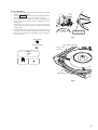
6-1. MechaniCAL Adjustments
Pop Up Mechanism Adjustment
1. Turn on the power and set the dick to number 24.
2. With the power ON, while pressing the GROUP FILE and
MEGA CONTROL buttons, press the 1/u button to enter
the Adjastment mode.
3. Rotate the JOG dial and select the mechanism adjustment mode.
(“Mech Adjust” is displayed.)
Press the JOG dial.
4. Keep pressing the GROUP 1 button to operate the loading
mechanism, and continue pressing until the disc table locks.
(Fig-1)
5. Keep pressing the GROUP 2 button to raise the pop up part.
6. Loosen the adjusting screw, move the screwdriver left and right
until the lever (POP UP) does not touch the slit wall, and secure
the screw. (Fig-2)
At this position,this
part will be locked.
FIg-1
The following buttons have special functions in this mode.
GROUP 1
GROUP 5
GROUP 2
GROUP 6
button: Loading mechanism IN operation
button: Loading mechanism OUT operation
button: Pop up part UP operation
button: Pop up part DOWN operation
Cover (chassis 400)
Lever (POP-UP 400)
Fix to the center so that the
lever (POP-UP 400) does
not touch the slit.
FIg-2
16
Sensor Adjustment
1. Enter the adjustment mode and select “Mech Adjust” with the
JOG dial, and press the dial.
2. Press the GROUP 1 button to operate the loading mechanism,
and continue pressing until the disc table locks. (Fig-3)
3. Loosen the fixing screw and move the holder so that both PLAY
button LED (green) and the ARTIST MODE button LED
(green) light.
If the holder is not in the correct position, the MEGA
CONTROL button LED (orange) or the PAUSE button LED
(orange) lights.
4. Moving the disc table right and left with a hand after the screw
is fixed, the table will move by the play of a disc table. If the
LEDs light up alternately, the adjustment will be performed
correctly. (Fig-4)
At this position,this
part will be locked.
FIg-3
ARTIST MODE
MEGA CONTROL
Holder (table sensor 400)
S tight, screw
(PTTWH 3 × 6)
Table (400) assembly
Swing
FIg-4
17
6-2. ELECTRICAL ADJUSTMENT
Note: A clear RF signal waveform means that the shape “◊” can be
clearly distinguished at the center of the waveform.
Note:
1. CD Block is basically designed to operate without adjustment.
Therefore, check each item in order given.
2. Use YEDS-18 disc (3-702-101-01) unless otherwise indicated.
3. Use an oscilloscope with more than 10MΩ impedance.
4. Clean the object lens by an applicator with neutral detergent
when the signal level is low than specified value with the
following checks.
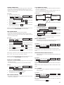
S-Curve Check
RF signal waveform
VOLT/DIV : 200mV
TIME/DIV : 500ns
+0.25
level : 1.2 –0.20
Vp-p
Adjustment Location: BD board (See page 19)
Oscilloscope
E-F Balance Check
BD board
Oscilloscope
TP (FE1)
TP (VC)
BD board
Procedure :
1. Chuck the disc (YEDS-18) beforehand, and disconnect the
power cord from the outlet.
2. Connect oscilloscope to test point TP (FE1) on BD board.
3. Connect test point (ADJ) on MAIN board to ground with lead
wire.
4. The ADJ mode is set when the power cord is inserted into the
outlet and power is supplied.
5. The fifth track is played automatically.
6. Press the CHECK button.
7. Check the oscilloscope waveform (S-curve) is symmetrical
between A and B. And confirm peak to peak level within 3±1
Vp-p.
S-curve waveform
Symmetry
A
TP (TE)
TP (VC)
Procedure :
1. Chuck the disc (YEDS-18) beforehand, and disconnect the
power cord from the outlet.
2. Connect oscilloscpe to test point TP (TE) on BD board.
3. Connect test point (ADJ) on MAIN board to ground with lead
wire.
4. The ADJ mode is set when the power cord is inserted into the
outlet and power is supplied.
5. The fifth track is played automatically.
6. Press the GROUP 3 button. (The tracking servo and the
sledding servo are turned OFF.)
7. Check the level B of the oscilliscope's waveform and the A
(DC voltage) of the center of the Traverse waveform.
Confirm the following :
A/B x 100 = less than ± 22%
Within 3 ± 1 Vp-p
Traverse waveform
B
Center of the waveform
Pressing the 1/u button stops the output of the waveform (s
curve).
9. After check, remove the lead wire connected in step 3.
Note : • Try to measure several times to make sure than the ratio of
A : B or B : A is more than 10 : 7.
• Take sweep time as long as possible and light up the
brightness to obtain best waveform.
B
8.
A (DC voltage)
0V
Level : 1.3 ± 0.6 Vp-p
8.
Adjustment Location: BD board (See page 19)
Press the GROUP 8 button. (The tracking servo and sledding
servo are turned ON.) Confirm the C (DC voltage) is almost
equal to the A (DC voltage) is step 7.
RF Level Check
Traverse waveform
Oscilloscope
BD board
TP (RF)
TP (VC)
Procedure :
1. Connect oscilloscope to test point TP (RF) on BD board.
2. Turn Power switch on.
3. Put disc (YEDS-18) in to play the number five track.
4. Confirm that oscilloscope waveform is clear and check RF
signal level is correct or not.
C (DC
voltage)
0V
Tracking servo
Sledding servo
OFF
9.
Tracking servo
Sledding servo
ON
Disconnect the lead wire of TP1 (ADJ) connected in step 2.
Adjustment Location: BD board (See page 19)
18
Disc Sensor Adjustment
Be sure to perform this adjustment after sensor adjustment in
MECHANICAL ADJUSTMENT.
5.
Connection:
MAIN board
TP1
D.S
GND
T.P
Oscilloscope
6.
D.S: Pin 1
T.P: Pin 3
Rotate the DISC/CHARACTER knob in the counterclockwise
direction and the disc table starts to rotate in the same direction.
Check that the waveform at this time is the same as that in step
4. If larger by a considerable extent, rotate the DISC/
CHARACTER knob in the clockwise direction and the disc
table starts to rotate in the same direction. Repeat from step 4.
Rotate RV501 of the MAIN board and adjust so that the H and
L portions of the D.S waveform become the same.
CH1
CH2
Waveform:
CH1
D.S
D.S
CH1
Adjust so that these widths
become the same.
Adjustment Location
CH2
1.
2.
3.
4.
T.P
Connect the oscilloscope to Pins 1, 2, and 3 of TP1 of the
MAIN board.
Check that no discs are loaded in the unit.
With the power ON, while pressing the GROUP FILE and
MEGA CONTROL buttons, press the 1/u button. Rotate
the DISC/CHARACTER dial, select “Table Rotation” and
press the dial.
The disc table starts to rotate in the clockwise direction.
Loosen the fixing screw, move the mounting board (SENSOR),
and secure the mounting board (SENSOR) at the point the H
portion of the T.P waveform comes the center of the H portion
of the D.S waveform.
[ BD BOARD ] – Side B –
TP
(FE1)
IC102
TP
TP (RF)
(TE)
IC103
D. sens (out) board
TP
(VC)
S tight, screw
(PTTWH 3 × 6)
CH1
D.S
CH2
T.P
Should be at the center
19
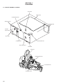
SECTION 7
DIAGRAMS
7-1. CIRCUIT BOARDS LOCATION
LED board
MAIN board
D. SENS (IN) board
DISPLAY board
TRANS board
D. SENS
(OUT) board
KEY board
T. SENS board
D. MOTOR board
DOOR SW board
JOG board
BD board
LOADING SW board
L. T. MOTOR board
LOCK SW board
20