1
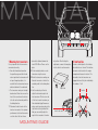
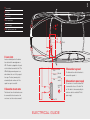
MANUAL
MANUAL
MANUAL
MANUAL
MANUAL
2
CONTENTS
BLINDER M20 X-TREME
comes complete with
Mounting outline
Mounting guide
Electrical guide
Police laser guns
Product registration
Warranty service
Consumer warranty
BLINDER worldwide service
2
3
4
5
6
6
7
7
7
BLINDER M20 X-TREME
LASERJAMMER
BLINDER M20 X-TREME
comes complete with
Thank you for buying the BLINDER M20
X-TREME LASERJAMMER. When
mounted correctly, the BLINDER M20
X-TREME LASERJAMMER will
effectively protect you against the police
laser speed control.
➤ 2 pcs. Jammer / detector transceivers
➤ Interface box
➤ Electrical wire with laser alert LED, Audible
Beeper alert and output to auto-mute
➤ Mounting bracket for the LED
➤ On / off switch
➤ Electrical wires for connecting on / off
switch to power supply 12 volt.
➤ Spirit level for correct installing of the
transceivers
➤ 1 pcs. Mounting fittings including
➤ 4 brackets for mounting
Please read this installation guide
carefully before installation.
We strongly recommend that a professional install your BLINDER M20
X-TREME.
INSTALLATION GUIDE
➤ 8 screws for mounting the brackets on
the transceivers
➤ 8 screws for mounting the brackets on
the car
➤ 8 washers for mounting the brackets
on the car
➤ Product registration card
MAN
MANUAL
3
1 Start with mounting the two transceivers in the front of the car. Route the
cables to the car’s interior for connection to the interface box.
2 Locate a suitable place for the interface box inside the car’s interior.
The interface box must not be mounted in the engine compartment because of moisture. The two cables from
the transceivers are plugged into two
of the jacks indicated by the numbers
1 to 4.
3 Locate a suitable place for the buzzer
laser alert and the warning/power on
LED. The cable is plugged into the
jacks on the interface box marked
"alert".
4 The red wire (+) from the interface
box is connected to the on / off
switch. The on / off switch is then
connected by the extension cable to a
switched 12-volt power supply.
NUAL
MOUNTING OUTLINE
5 The black wire from the interface box
is connected to ground (-).
6 The blue wire from the interface box
can be connected to the auto mute on
the car-stereo (see the car-stereo
manual).
MANUAL
4
1 Mounting the transceivers
It’s very important that the transceivers
are mounted correctly:
➤ Since the infrared laser beam from
the speed laser gun and the infra red
return signal from the transceivers will
not pass through any objects, it is
essential that the transceivers have an
unobstructed view of the road ahead.
➤ The transceivers must point straight
ahead and not follow the curve on the
front of the car and must be horizontal to the road surface and parallel to
the driving direction.
1.1 Determine the best location for the
two laser transceivers. For optimum
performance, install each transceiver
on either side of the front license
plate with a distance between the
two of 50 – 60 cm. Please see the
photo.
1.2 Fit the mounting brackets on each
transceiver using the screws.
1.3 Mount the transceivers making sure
that each transceiver is level to the
road and parallel to the driving direction.
1.4 Use the enclosed spirit level to
adjust the horizontal angle for the
two transceivers. On the outer side
of the front on each transceiver you
find a detachable plug. Remove one
plug on each transceiver, and put the
spirit level into the cylindrical hole.
Now you can carefully adjust the
angle of the transceivers to horizon-
MOUNTING GUIDE
tal position. After finishing the
adjustment, re-mount the two plugs
into the front of each transceiver.
Spirit level
Level to the road
2 Interface Box
Locate a suitable place for the interface
box inside the car’s interior. The interface
box must not be located in the engine
compartment because of moisture. The
two cables from the transceivers are
plugged into two of the jacks indicated by
the numbers 1 to 4.
Parallel
L
1 Transceivers
2 Interface
3 Laser alert
4 Auto mute (blue)
5 Ground (black)
6 12V. Ignition power (red)
5
3
1
4
5
6
1
12 volt
2
3 Laser alerts
Locate a suitable place for the buzzer
laser alert and the warning/power on
LED. The cable is plugged into the jacks
on the interface box marked "alert". The
LED will light green when power is on
and red when the car is hit by a speed
laser gun. The laser jamming starts
automatically and continues until the
speed laser gun is turned off.
The blue wire from the interface box can
be connected to the auto mute on the
car-stereo (see the car-stereo manual).
Black
Red
Alert
1
2
3
Mute
5 Connection to ground
Ground
The black wire from the interface box is
connected to ground (-).
ON/OF
switch
swicthed
12V
Interface
4 Connection to auto mute
Blue
4
Fuse 1A
ELECTRICAL GUIDE
6 Connection to power supply
The red wire (+) from the interface box
is connected to the on / off switch. The
on / off switch is then connected by the
extension cable to a switched 12-volt
power supply.
6
DEALING WITH POLICE
LASER GUNS
PRODUCT REGISTRATION
To avoid any problems with the police,
we strongly recommend following the
method mentioned below when dealing
with police laser guns:
Please fill in and send the enclosed
Product Registration Form. By sending
this registration form, we can offer online technical help and other support on
the Internet.
As soon as you hear the BLINDER laser
warning signal, you must immediately
1. Slow down to legal speed limits
2. Switch off the BLINDER
ONLINE REGISTRATION
You are welcome to register your
BLINDER Laserjammer on the Internet.
Go to: www.blinder.dk
In that way you will allow the police to
get a clear speed measurement without
attracting any attention. Often the police
need two or tree shoots before getting a
valid speed measurement. Therefore turn
off the BLINDER within a few seconds,
and no one will suspect that a laser jammer is being used!
WARNING!
Do not look directly into the BLINDER
M20 X-TREME with the naked eye at
close range. You won’t see anything, but
you might cause eye damage after
prolonged exposure. Remember, the
BLINDER M20 X-TREME emits infrared
(IR) light, which is not visible to the
human eye, regardless of how strong
it is.
WARNING!
• BLINDER does not advocate exceeding the legal speed limits.
• BLINDER shall not be held responsible for any injuries that could occur
due to improper installation or usage
of the product.
• Professional installation is recommended.
BLINDER USA
11000 Prosperity Farms Road
Suite 105
Palm Beach Gardens
FL 33410, USA
Phone: 561-373-3946
Fax: 561-625-4433
[email protected]
www.blinder.us
BLINDER WARRANTY SERVICE
If service is required, please follow the
instructions below.
To obtain service during the one-year
warranty period, please contact:
OTHER COUNTRIES:
BLINDER International
Strandlodsvej 13
DK-2300 Copenhagen S
Denmark
Phone +45 3296 3200
Fax +45 3296 3231
[email protected]
www.blinder.dk
MANUAL
MANUAL
7
Shipping your BLINDER for
repair or replacement
BLINDER Consumer Warranty
For your own protection, obtain a proof
of delivery receipt. Shipping costs are
your responsibility.
This warranty covers all defects in materials and workmanship. This warranty does
not apply if the unit has been subject to
physical abuse, improper installation,
modification, or if the housing or serial
number of the unit has been removed.
Enclose with your unit the following information:
Your name, complete return address
and written description of the problem
(no P.O. Box please).
A telephone number where you can be
reached during business hours.
A copy of your dated sales receipt.
Scratches and stone damage can also
affect output. If the lens becomes too
badly damaged, order replacement
lenses separately. We suggest replacing
the lens every 12 months.
When the ignition is turned on, the
upstart self-test function will, turnon the
interior alert for two seconds telling you
that the BLINDER M20 X-TREME is
ready to protect you. The warning LED
will turn green.
BLINDER WORLDWIDE
SERVICE
LIMITED ONE-YEAR WARRANTY
BLINDER International manufactures its
products using parts and components,
which are new or equivalent to new in
accordance with industry standard practices.
The enforceability of this warranty is
limited to the original consumer purchaser. It is not transferable to, or enforceable by, any subsequent owner.
In the event of a defect, malfunction
or other failure to conform to this warranty, BLINDER International will, at is
sole discretion, repair or replace the unit
at no charge. You are responsible for all
shipping costs in connection with warranty service pursuant to this warranty.
This warranty commences on the date
of the retail purchase and shall be effective for a period of one year.
There are no express warranties
covering the unit other than those set
forth in this warranty. All implied warranties are limited to the one-year period of
this warranty and no warranties,
expressed or implied, extend beyond this
one-year period. Some states do not
allow limitation on how long an implied
warranty lasts, so the above limitation
may not apply to you.
BLINDER International will in no event
be liable for any consequential, incidental, indirect or special damages (including, but not limited to, lost profits) arising out of or in connection with the use,
misuse or function of the unit. Some states do not allow the exclusion of limitation of incidental or consequential damages, so the above limitation or exclusion
may not apply to you.
You must provide a copy of a dated
receipt for your unit in order to receive
service under warranty.
USA: www.blinder.us
[email protected]
Other: www.blinder.dk
[email protected]
Service and control
Keep in mind that snow and dirt on the
lens decrease the output of the BLINDER
M20 X-TREME’s range to where it may
not detect or jam the police laser gun
when you need it. Therefore the lens
should be kept clean.
MANUAL
MANUAL
MANUAL
MANUAL
MANUAL
BLINDER International
Strandlodsvej 13
DK-2300 Copenhagen S
Denmark
Phone +45 3296 3200
Fax +45 3296 3231
[email protected]
www.blinder.dk