1
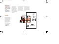
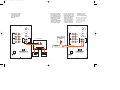
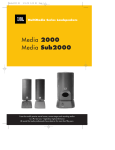
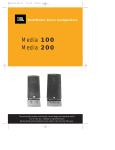
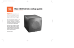
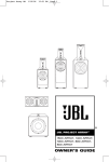
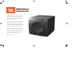
PSW-D112
11/9/99
11:02 AM
Page 1
PSW-D112
simple setup guide
thank you for choosing JBL. For more
than 50 years, JBL has been involved in every
aspect of music and film recording and reproduction, from live performances to the recordings you
play in your home, car or office.
We’re confident that the JBL loudspeaker you have
chosen will provide every note of enjoyment that
you expected – and that when you think about purchasing additional audio equipment for your home,
car or office, you will once again choose JBL.
Please take a moment to complete the enclosed
profile card. It enables us to keep you posted on
our latest advancements, and helps us to better
understand our customers and build products that
meet their needs and expectations.
JBL Consumer Products
PSW-D112
11/9/99
11:02 AM
Page 2
read first! Important Safety Precautions!
CAUTION
RISK OF ELECTRIC SHOCK
DO NOT OPEN
CAUTION: To prevent electric shock,
do not remove the grounding plug
on the power cord, or use any plug
or extension cord that does not have
a grounding plug provided.
Make certain that the
AC outlet is properly grounded.
Do not use an adapter plug
with this product.
The lightning flash with arrowhead symbol,
within an equilateral triangle, is intended to
alert the user to the presence of uninsulated
“dangerous voltage” within the product’s
enclosure that may be of sufficient magnitude to constitute a
risk of electric shock to persons.
The exclamation point within an equilateral
triangle is intended to alert the user to the
presence of important operating and
maintenance (servicing) instructions in the
literature accompanying the appliance.
1. Read Instructions. All
the safety and operating
instructions should be
read before the product is
operated.
2. Retain Instructions. The
safety and operating instructions should be retained for
future reference.
3. Heed Warnings. All warnings on the product and in
the operating instructions
should be adhered to.
4. Follow Instructions. All
operating and use instructions should be followed.
5. Water and Moisture. The
product should not be used
near water – for example,
near a bathtub, washbowl,
kitchen sink, laundry tub, in
a wet basement or near a
swimming pool, and the like.
6. Accessories. Do not place
this product on an unstable
cart, stand, tripod, bracket
or table. The product may
fall, causing serious injury to
a child or adult, and serious
damage to the product. Use
only with a cart, stand, tripod, bracket or table recommended by the manufacturer,
or sold with the product.
Any mounting of the product
should follow the manufacturer’s instructions, and
should use a mounting
accessory recommended by
the manufacturer.
7. Wall or Ceiling
Mounting. The product
should be mounted on a
wall or ceiling only when
and as recommended by the
manufacturer.
8. Ventilation. Slots and
openings in the cabinet are
provided for ventilation and
to ensure reliable operation
of the product and to protect
it from overheating, and
these openings must not be
blocked or covered. The
openings should never be
blocked by placing the product on a bed, sofa, rug or
other similar surface. This
product should not be placed
in a built-in installation
such as a bookcase or rack
unless proper ventilation
is provided or the manufacturer’s instructions have
been adhered to.
9. Heat. The product should
be situated away from heat
sources such as radiators,
heat registers, stoves or
other products that produce
heat. If placed near an
amplifier, check with
the manufacturer for
applicability.
10. Power Sources. This
product should be operated
only from the type of power
source indicated on the
marking label. If you are not
sure of the type of power
supply to your home, consult
your product dealer or local
power company. For products
intended to operate from
battery power, or other
sources, refer to the
operating instructions.
11. Grounding or
Polarization. This product
may be equipped with a
polarized alternating-current
line plug (a plug having one
blade wider than the other).
This plug will fit into the
power outlet only one way.
This is a safety feature. If
you are unable to insert the
plug fully into the outlet, try
reversing the plug. If the
plug should still fail to fit,
contact your electrician to
replace your obsolete outlet.
Do not defeat the safety purpose of the polarized plug.
12. Power-Cord Protection.
Power-supply cords should
be routed so that they are
not likely to be walked on or
pinched by items placed
upon or against them, paying particular attention to
cords at plugs, convenience
receptacles and the point
where they exit from the
product.
13. Cleaning. Unplug this
product from the wall outlet
before cleaning. Do not use
liquid cleaners or aerosol
cleaners. Use a damp cloth
for cleaning.
14. Nonuse Periods. The
power cord of the product
should be unplugged from
the outlet when left unused
for long periods of time.
15. Lightning. For added
protection for this product
during a lightning storm, or
when it is left unattended
and unused for long periods
of time, unplug it from the
wall outlet and disconnect
the antenna or cable system.
This will prevent damage to
the product due to lightning
and power-line surges.
16. Overloading. Do not
overload wall outlets, extension cords or integral convenience receptacles, as this
can result in a risk of fire or
electric shock.
–2–
17. Object and Liquid
Entry. Never push objects of
any kind into this product
through openings, as they
may touch dangerous voltage
points or short-out parts
that could result in a fire or
electric shock. Never spill
liquid of any kind on the
product.
f. The product does not
appear to operate normally
or exhibits a marked change
in performance.
18. Damage Requiring
Service. Unplug this product
from the wall outlet and
refer servicing to qualified
service personnel under the
following conditions:
a. The power-supply cord or
the plug has been damaged;
or
b. Objects have fallen onto,
or liquid has been spilled
into, the product; or
c. The product has been
exposed to rain or water; or
d. The product does not
operate normally when following the operating instructions. Adjust only those controls that are covered by the
operating instructions, as an
improper adjustment of other
controls may result in damage and will often require
extensive work by a qualified
technician to restore the
product to its normal operation; or
e. The product has been
dropped, or the enclosure
damaged; or
20. Replacement Parts.
When replacement parts are
required, be sure the service
technician has used replacement parts specified by
the manufacturer or that
have the same characteristics as the original part.
Unauthorized substitutions
may result in fire, electric
shock or other hazards.
19. Attachments. Do not
use attachments not recommended by the product manufacturer, as they may cause
hazards.
21. Safety Check. Upon
completion of any service or
repairs to this product, ask
the service technician to
perform safety checks to
determine that the product
is in proper operating
condition.
22. Servicing. Do not
attempt to service this product yourself, as opening or
removing covers may expose
you to dangerous voltage or
other hazards. Refer all servicing to qualified service
personnel.
Part No. JBLULA 10/99
PSW-D112
11/9/99
11:02 AM
Page 3
Placement
• As a general rule, bass
response increases as a
subwoofer is placed closer
to a wall. Therefore, bass
output is maximized when
the subwoofer is placed in
a corner.
• It is also recommended
that the subwoofer be
positioned along the
same wall as the front
loudspeakers.
Low-frequency sounds are
normally omnidirectional,
meaning the listener can’t
tell where they are generated
from. However, frequencies
between 75Hz – 150Hz can
be localized, especially at
higher volume levels.
Positioning your subwoofer
as recommended will provide
the most natural soundstage
and imaging from your loudspeaker system.
Remember that these are just
guidelines. Since every listening room is different, JBL
strongly recommends experimenting with the positioning
of your subwoofer to obtain
the most pleasing results in
your room. One technique that
can help you find the ideal
subwoofer location is to temporarily place the subwoofer
near the main listening location. Then move around the
room and determine where you
hear the most pleasing bass
performance. This would then
be the ideal location for the
subwoofer.
120
90
150
RECEIVER/AMPLIFIER
Hookup
Phase
SPKR In
Left
When we designed the
PSW-D112 powered subwoofer,
our goal was to offer the user
the best possible performance
combined with the most flexible and complete installation
options. Please look over the
following four examples to
determine which description
best matches your system and
follow the corresponding
hookup instructions.
High
Pass
180
60
Right
0
180
L
120
90
150
R
60
–
+
–
Low
Pass
180
+
L
L
R Out
Line Level
L
R
R
SPKR Out
–
+
LEFT
SPEAKER
–
+
RIGHT
SPEAKER
1) If your receiver/amplifier
has no subwoofer
outputs or preamp
outputs for the left,
center and right
channels.
Power
On
Off
PSW-D112
Digital Amplification
–3–
In
PSW-D112
11/9/99
11:02 AM
Page 4
3) If your receiver/amplifier
has a single (mono) subwoofer output or LFE output, you may connect the
output to either the Left
or Right line-level input
on the subwoofer.
However, to maximize the
subwoofer’s performance,
we recommend that you
2) If your receiver/amplifier
has subwoofer outputs
or preamp output jacks
for the left and right
channels.
use a “Y”-connector (not
included). Plug the single
male end of the “Y”-connector into the subwoofer
output on the receiver/
amplifier, and connect
each of the 2 female connectors to an RCA-type
interconnect cable. Then
connect the 2 intercon-
nect cables to the Left
and Right line-level
inputs on the PSW-D112.
Note: If your receiver/processor contains Dolby* Digital or
DTS® surround processing
technology, then set the
“Low-Pass” control on the
180Hz position.
120
120
90
150
High
Pass
180
60
90
Phase
SPKR In
L
L
120
90
150
60
L
90
RECEIVER/PREAMPLIFIER
Low
Pass
180
L
60
R Out
L
R
150
R
Subwoofer
Output/LFE
RECEIVER/AMPLIFIER
L
Low
Pass
180
L
Line Level
R
0
180
120
R
High
Pass
Phase
SPKR In
0
180
150
180
60
R Out
Line Level
SUBWOOFER OUT
LEFT
RIGHT
In
L
R
SPKR Out
R
SPKR Out
MAIN SPEAKER OUTPUT
+
RIGHT
–
–
+
LEFT
Power
Power
On
Off
On
PSW-D112
Off
Digital Amplification
PSW-D112
Digital Amplification
+
–
RIGHT
LOUDSPEAKER
–
+
LEFT
LOUDSPEAKER
–4–
In
PSW-D112
11/9/99
11:02 AM
Page 5
4) If your receiver/amplifier has preamp output
jacks and main input
jacks for the left and
right channels, or you
have a separate preamp/
processor and
power amplifier.
This method of hookup can
offer the highest level of
performance for your
complete loudspeaker system.
The PSW-D112 incorporates a
variable high-pass crossover
in addition to a variable low-
pass crossover. When hooked
up as shown, the subwoofer
will limit the low-frequency
information that is returned
to your receiver/amplifier.
Your receiver/amplifier does
not need to waste valuable
power reproducing the low
frequencies. In addition,
since no low-frequency
information is being sent
to your main loudspeakers,
they are able to reproduce
mid and high frequencies
with greater clarity.
120
90
150
High
Pass
180
60
Phase
SPKR In
0
180
L
120
90
150
R
60
Low
Pass
180
RECEIVER/AMPLIFIER
L
L
R Out
PRE
OUT
Line Level
L
R
R
In
MAIN
IN
LEFT
RIGHT
SPKR Out
MAIN SPEAKER OUTPUT
+
RIGHT
–
–
+
LEFT
Power
On
Off
PSW-D112
Digital Amplification
+
–
RIGHT
LOUDSPEAKER
–5–
–
+
LEFT
LOUDSPEAKER
PSW-D112
11/9/99
11:02 AM
Page 6
Operation
Level Control
Power
When the unit is plugged in
and power is on and no signal
is received, the LED on the
front of the unit will turn red.
When a signal is present, the
LED will turn green. Note: It
will take several minutes for
the LED to turn from green to
red after the input signal to
the subwoofer is removed.
Due to JBL’s unique, high-efficiency digital-amplifier design,
power consumption is minimal
when the subwoofer is not
receiving a signal. Of course,
the subwoofer can be turned
off, whenever desired.
Video Contour
The subwoofer Level Control,
located on the front panel,
adjusts the volume of the
subwoofer relative to the rest
of the system. Proper level
adjustment depends on several
variables such as room size,
subwoofer placement, type of
main speakers and listener
position. Adjust the subwoofer
level so that the volume of
the bass information is pleasing to you.
The video-contour switch,
located on the front panel,
optimizes the subwoofer’s
performance for movie listening. When the video-contour
switch is “on,” the subwoofer’s
performance is tailored to
deliver the impact and
are using smaller bookshelf
speakers that do not extend
to the lower bass frequencies,
set the high-pass crossover
control to a higher setting,
between 125Hz – 180Hz.
With this setting, your main
speakers will not have the
burden of reproducing any
low-frequency sounds.
• If you hooked up your subwoofer as shown in Hookup 1
on page 3, the high-pass
frequency is fixed at 180Hz.
• If you hooked up your
subwoofer as shown in
Hookup 2 or Hookup 3 on
page 4, no high-pass
control adjustments can be
made from the subwoofer.
Unless your receiver/ampli-
fier incorporates a high-pass
crossover, your main speakers will continue to get a
full-range signal.
Crossover Adjustments
Low-Pass Control
The Low-Pass control determines the highest frequency at
which the subwoofer reproduces
sounds. If your main speakers
can comfortably reproduce
some low-frequency sounds,
set this control to a lower
frequency setting, between
50Hz – 100Hz. This will
concentrate the subwoofer’s
efforts on the ultradeep bass
sounds required by today’s
films and music. If you are
using smaller bookshelf
speakers that do not extend to
the lower bass frequencies, set
the low-pass crossover control
to a higher setting, between
120Hz – 180Hz.
120
90
150
High
Pass
180
60
120
90
150
60
180
Low
Pass
High-Pass Control
• If you hooked up your subwoofer as shown in Hookup 4
on page 5, you also have
the capability of adjusting
the high-pass frequency.
The High-Pass control
determines the frequency at
which the main speakers
will start reproducing
sounds. If your main speakers can comfortably reproduce some low-frequency
sounds, also set this
control to a lower frequency
setting, between 50Hz –
100Hz. This will concentrate
the subwoofer’s efforts to
the ultradeep bass sounds,
while your main speakers
continue to reproduce the
mid-bass information. If you
–6–
Final adjustment and blending
of the low-pass and high-pass
controls may evolve over several listening sessions. A good
starting point would be to set
both the low- and high-pass
controls to the same frequency
and adjust from that point.
excitement of today’s movies.
The green LED will illuminate
when the video-contour switch
is on.
PSW-D112
11/9/99
11:02 AM
Page 7
Phase Control
Troubleshooting
If you used the high-level
(speaker) inputs and there
is no sound from any of the
speakers:
The Phase Control determines
whether the subwoofer
speaker’s piston-like action
moves in and out with the
main speakers, 0°, or opposite
the main speakers, 180°. There
is no correct or incorrect setting. Proper phase adjustment
depends on several variables
such as subwoofer placement
and listener position. Adjust
the phase switch to maximize
bass output at the listening
position.
Remember, every system,
room and listener is different.
There are no right or wrong
settings; this switch offers
the added flexibility to adjust
your subwoofer for optimum
performance for your specific
listening conditions. Should
you decide to fine-tune your
system for optimum
performance, be patient and
trust your ears. It will be
worth the effort involved to
fully “tweak” your system.
• Check that receiver/amplifier
is on and a source is playing.
• Check that powered subwoofer is plugged in.
• Check all wires and connections between receiver/amplifier and speakers. Make sure
all wires are connected. Make
sure none of the speaker wires
are frayed, cut or punctured.
• Review proper operation
of your receiver/amplifier.
–7–
If there is low (or no) bass
output:
• Make sure the connections
to the left and right “Speaker
Inputs” have the correct
polarity (+ and –).
• Make sure that the subwoofer is plugged into an
active electrical outlet.
• Adjust the crossover point.
• Flip the Phase Control switch
to the opposite position.
• If you are using a Dolby*
Digital/DTS® receiver or
processor, make sure that the
subwoofer adjustments on
the receiver/processor are
set up correctly.
• Slowly turn the Level
Control clockwise until you
begin to hear the desired
amount of bass.
If you used the line-level
inputs and there is no sound
from the subwoofer:
• Check that receiver/amplifier
is on and a source is playing.
• Check that powered subwoofer is plugged in.
• Check all wires and connections between receiver/
amplifier and subwoofer. Make
sure all wires are connected.
Make sure none of the wires
are frayed, cut or punctured.
• Review proper operation of
your receiver/amplifier.
• Slowly turn the Level
Control clockwise until you
begin to hear the desired
amount of bass.
• Make sure that you have
configured your receiver/
processor so that the subwoofer/LFE output is on.
PSW-D112
11/9/99
11:02 AM
Page 8
Specifications
PSW-D112
Amplifier Power (RMS)
250 Watts
Driver
12" High-Polymer Laminate
Inputs
Line Level and Speaker Level
Outputs
Line Level and Speaker Level
Low-Pass Frequency
Continuously variable from 60Hz – 180Hz
High-Pass Frequency
Continuously variable from 60Hz – 180Hz
when using line-level outputs;
180Hz when using speaker-level outputs
Frequency Response
28Hz – low-pass crossover setting
Dimensions
Weight
17-1/2 x 17-1/2 x 19-1/8"
445 x 445 x 486mm
40 lbs/18.2 kg
JBL Consumer Products
250 Crossways Park Drive, Woodbury, NY 11 797
8500 Balboa Boulevard, Northridge, CA 91329
1-800-336-4JBL (4525) (USA only)
1999 JBL, Incorporated
©
JBL is a registered trademark of JBL, Incorporated.
*Trademark of Dolby Laboratories.
DTS is a registered trademark of Digital Theater Systems, Inc.
Printed 11/99
Part No. 200731